
Chaptr 2 Limit Fit Tolerance Co C 505







- Slides: 24
Chaptr -2 Limit, Fit, Tolerance
Co C 505. 2 Know the system of limits, fits, tolerances and correlate it with machine drawing.
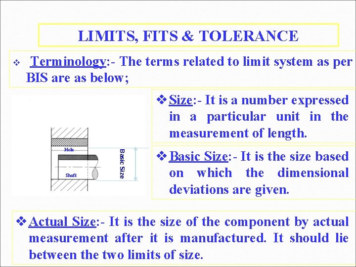
LIMITS, FITS & TOLERANCE Terminology: - The terms related to limit system as per BIS are as below; Size: - It is a number expressed in a particular unit in the measurement of length. Shaft Basic Size Hole Basic Size: - It is the size based on which the dimensional deviations are given. Actual Size: - It is the size of the component by actual measurement after it is manufactured. It should lie between the two limits of size.
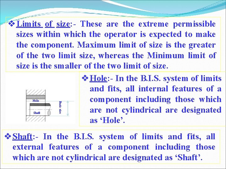
Hole Shaft Basic size Limits of size: - These are the extreme permissible sizes within which the operator is expected to make the component. Maximum limit of size is the greater of the two limit size, whereas the Minimum limit of size is the smaller of the two limit of size. Hole: - In the B. I. S. system of limits and fits, all internal features of a component including those which are not cylindrical are designated as ‘Hole’. Shaft: - In the B. I. S. system of limits and fits, all external features of a component including those which are not cylindrical are designated as ‘Shaft’.
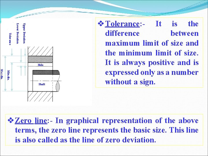
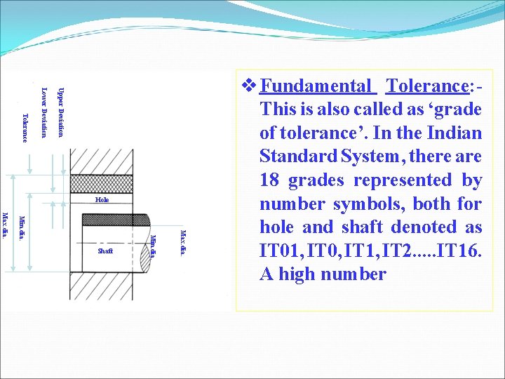
Upper Deviation Lower Deviation Tolerance Hole Min. dia. Max. dia. Shaft Tolerance: - It is the difference between maximum limit of size and the minimum limit of size. It is always positive and is expressed only as a number without a sign. Zero line: - In graphical representation of the above terms, the zero line represents the basic size. This line is also called as the line of zero deviation.
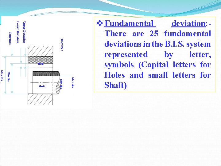
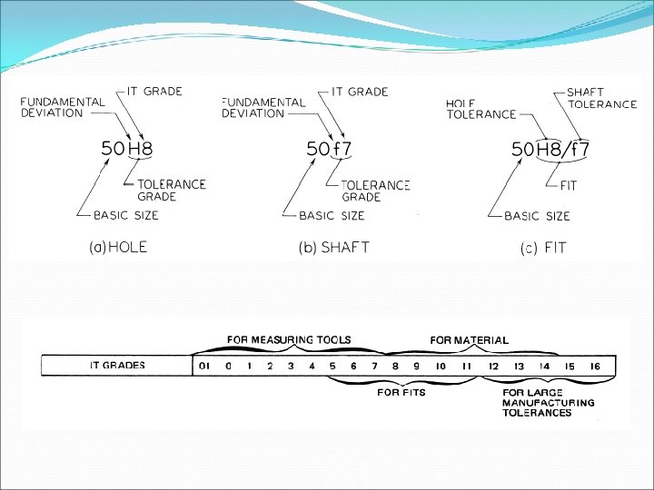
Tolerance Upper Deviation Lower Deviation Tolerance Hole Max. dia. Min. dia. Max. dia. Shaft Fundamental deviation: There are 25 fundamental deviations in the B. I. S. system represented by letter, symbols (Capital letters for Holes and small letters for Shaft)
Upper Deviation Lower Deviation Tolerance Hole Max. dia. Min. dia. Max. dia. Shaft Fundamental Tolerance: This is also called as ‘grade of tolerance’. In the Indian Standard System, there are 18 grades represented by number symbols, both for hole and shaft denoted as IT 01, IT 0, IT 1, IT 2. . . IT 16. A high number
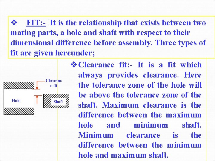
FIT: - It is the relationship that exists between two mating parts, a hole and shaft with respect to their dimensional difference before assembly. Three types of fit are given hereunder; Clearance fit: - It is a fit which always provides clearance. Here Clearanc e fit the tolerance zone of the hole will be above the tolerance zone of the Hole Shaft shaft. Maximum clearance is the difference between the maximum hole and minimum shaft. Minimum clearance is the difference between the minimum hole and maximum shaft.
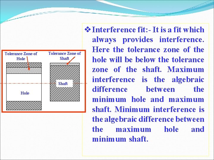
Tolerance Zone of Hole Tolerance Zone of Shaft Hole Interference fit: - It is a fit which always provides interference. Here the tolerance zone of the hole will be below the tolerance zone of the shaft. Maximum interference is the algebraic difference between the minimum hole and maximum shaft. Minimum interference is the algebraic difference between the maximum hole and minimum shaft.
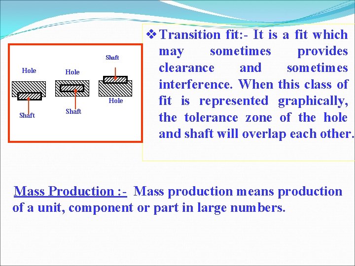
Shaft Hole Shaft Transition fit: - It is a fit which may sometimes provides clearance and sometimes interference. When this class of fit is represented graphically, the tolerance zone of the hole and shaft will overlap each other. Mass Production : - Mass production means production of a unit, component or part in large numbers.
Advantages: - 1. Time for the manufacture of components is reduced 2. The cost of pieces is reduced. 3. Spare parts can be quickly made available. Disadvantages: -1. Special purpose machines are necessary. 2. Jigs and Fixtures are needed. 3. Gauges are to be used instead of conventionalprecision instruments. 4. Initialexpenditurewillbe very high.
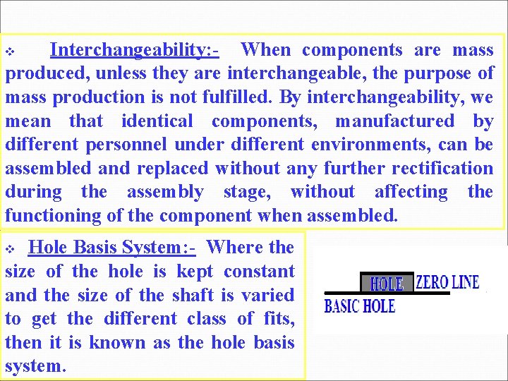
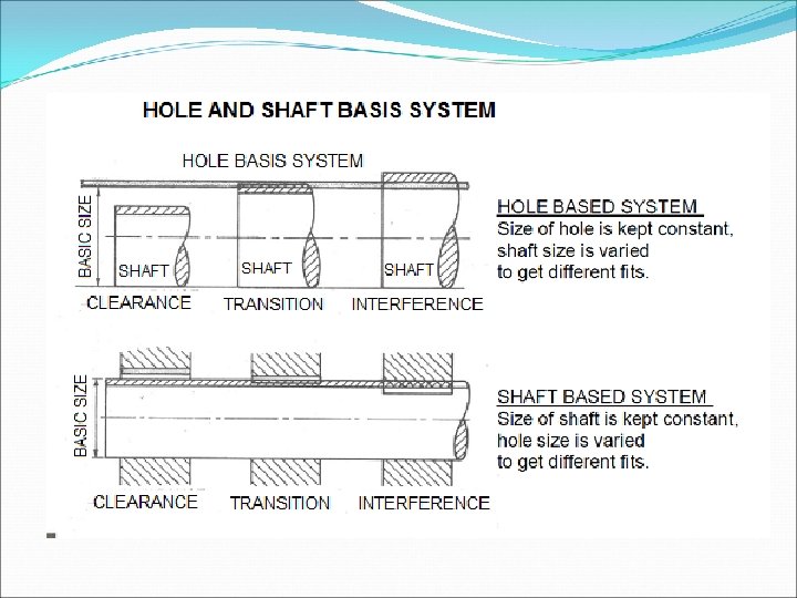
Interchangeability: - When components are mass produced, unless they are interchangeable, the purpose of mass production is not fulfilled. By interchangeability, we mean that identical components, manufactured by different personnel under different environments, can be assembled and replaced without any further rectification during the assembly stage, without affecting the functioning of the component when assembled. Hole Basis System: - Where the size of the hole is kept constant and the size of the shaft is varied to get the different class of fits, then it is known as the hole basis system.
MQAR Metrology, Quality Assurance & Reliability Text Books : Engg. Metrology by R. K. Jain
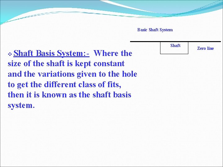
Basic Shaft System Shaft Basis System: - Where the size of the shaft is kept constant and the variations given to the hole to get the different class of fits, then it is known as the shaft basis system. Zero line
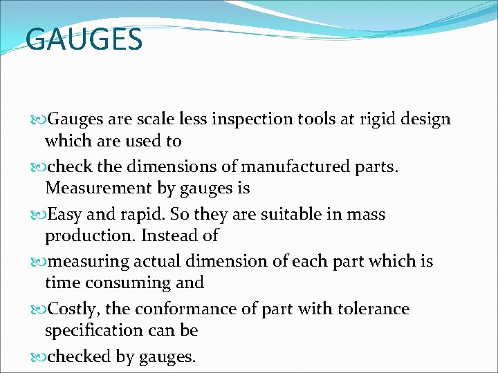
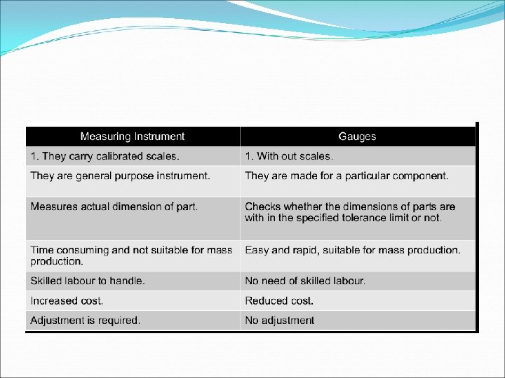
GAUGES Gauges are scale less inspection tools at rigid design which are used to check the dimensions of manufactured parts. Measurement by gauges is Easy and rapid. So they are suitable in mass production. Instead of measuring actual dimension of each part which is time consuming and Costly, the conformance of part with tolerance specification can be checked by gauges.
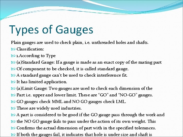
Types of Gauges Plain gauges are used to check plain, i. e. unthreaded holes and shafts. Classification: 1. According to Type (a)Standard Gauge: If a gauge is made as an exact copy of the mating part Of component to be checked, it is called standard gauge. A standard gauge can’t be used to check interference fit. It has limited application. (a)Limit Gauge: Two gauges are used to check each dimension of the Part i. e. upper and lower limit. These are “GO” and “NO-GO” gauges. GO gauges check MML and NO GO gauges check LML. These are widely used industries. A part is considered to be good if the GO gauge pass through the work and the NO GO gauge fails to pass under the action of its own weight. This Confirms the actual dimension of part with in the specified tolerances. If both the gauges fail, it indicates that hole is under size and shaft is
According to Purpose: a) Workshop gauge b) Inspection gauge c) Reference or master gauge d) Purchase inspection gauge 2. According to the form of the tested surface: a) Plug gauges for checking holes b) Snap or Ring or Gap gauges for checking the shaft 3. According to their design: a) Single limit or double limit gauges b) Single ended or double ended gauges c) Fixed and adjustable gauges
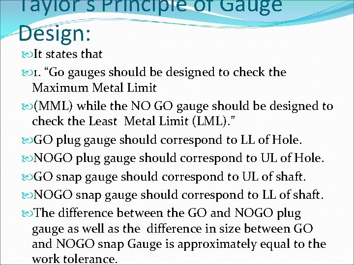
Taylor’s Principle of Gauge Design: It states that 1. “Go gauges should be designed to check the Maximum Metal Limit (MML) while the NO GO gauge should be designed to check the Least Metal Limit (LML). ” GO plug gauge should correspond to LL of Hole. NOGO plug gauge should correspond to UL of Hole. GO snap gauge should correspond to UL of shaft. NOGO snap gauge should correspond to LL of shaft. The difference between the GO and NOGO plug gauge as well as the difference in size between GO and NOGO snap Gauge is approximately equal to the work tolerance.
For universal Interchangeability it is essential to follow a uniform standard Through out the world. Indian standards (IS) are in line with ISO recommendations. It consists of 25 Holes designated by capital letter A, B, C, D, E, F, G, H, JS, J, K, M, N, P, R, S, T, U, V, X, Y, Z, ZA, ZB, ZC It consists of 25 shafts designated by small letter Recommendation for limits and fits for Engineering: For universal Interchangeability it is essential to follow a uniform standard Through out the world. Indian standards (IS) are in line with ISO recommendations. It consists of 25 Holes designated by capital letter A, B, C, D, E, F, G, H, JS, J, K, M, N, P, R, S, T, U, V, X, Y, Z, ZA, , ZC It consists of 25 shafts designated by smal letter a, b, c, d, e, f, g, h, js, j, k, m, n, p, r, s, t, u, v, x, y, z, za, zb, zc Each of holes and shafts has a choice of 18 Grades of Tolerances Designated as: IT 01, IT 0, IT 1, IT 2, IT 3, ……… IT 15, IT 16. IT 01 – 0. 3 + 0. 008 D IT 0 – 0. 5 + 0. 012 D IT 1 – 0. 8 + 0. 020 D IT 2 – 2. 7 i; IT 3 - 3. 7 i; IT 4 – 5 i; IT 5 – 7 i; IT 6 – 10 i; IT 7 – 16 i; IT 8 – 25 i; IT 9 – 40 i; IT 10 – 64 i; IT 11 – 100 i; IT 12 – 160 i; IT 13 – 250 i; IT 14 – 400 i; IT 15 – 640 i; IT 16 – 1000 i.
Selective Assembly In selective assembly components produced are classified into groups according to their sizes by automatic gauging. This is done for both Holes and Shafts and then corresponding parts will be matched properly. It reduces chance of defective assembly and also the cost of assembly as parts may be produced in wider tolerances. Ex: Assembly of piston with cylinder bores.