Hole and Shaft System Maximum Clearance Dmax dmin


 fit. when the shaft is always larger in diameter")


- Slides: 33
Hole and Shaft System
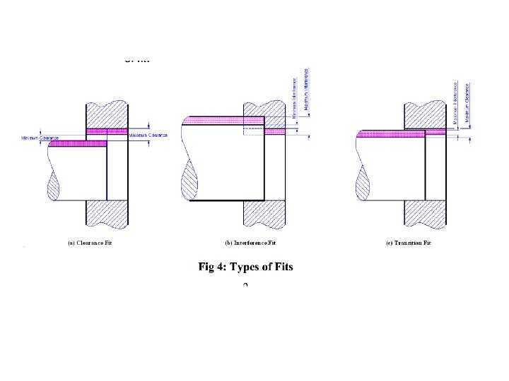
Maximum Clearance : Dmax - dmin Minimum Clearance : Dmin - dmax
Clearance Fit A clearance fit. The shaft is always smaller than the hole Tolerance on shaft : 0. 002 Tolerance on hole : 0. 002 minimum clearance : 0. 600 - 0. 595 = 0. 005 inch maximum clearance : 0. 602 - 0. 593= 0. 009 inch The 0. 005 clearance in for the tightest possible fit.
Interference Fit An Force (interference) fit. when the shaft is always larger in diameter than the hole parts must be assembled by pressure or heat expansion. Tolerance on shaft : 0. 001 Tolerance on hole : 0. 001 minimum clearance : 0. 500 - 0. 503= -0. 003 in (the tightest fit 0. 003 in interference) maximum clearance : 0. 501 - 0. 502 = -0. 001 in (the loosest fit 0. 001 in interference) Maximum clearance=Minimum interference Minimum clearance=Maximum interference
Transistion Fit A transition fit exist when the maximum clearance is positive and the minimum clearance is negative Tolerance on shaft : 0. 005 Tolerance on hole : 0. 005 minimum clearance : 0. 500 - 0. 507 = 0. 007 inch The tightest fit is 0. 007 in interference. maximum clearance : 0. 505 – 0. 502 = 0. 003 inch The loosest fit is 0. 003 in clearance Transition fits are used only for locating a shaft relative to a hole, where accuracy is important but either a clearance or interference is permitted.
Allowance ü Allowance: An allowance is the intentional difference between the maximum material limits, that is, LLH and HLS (minimum clearance or maximum interference) of the two mating parts. It is the prescribed difference between the dimensions of the mating parts to obtain the desired type of fit. ü Allowance may be positive or negative. Positive allowance indicates a clearance fit, and an interference fit is indicated by a negative allowance. Allowance = Dmin - dmax
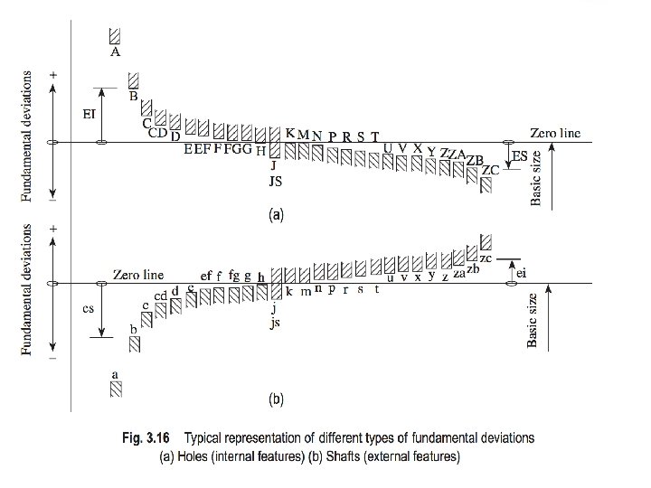
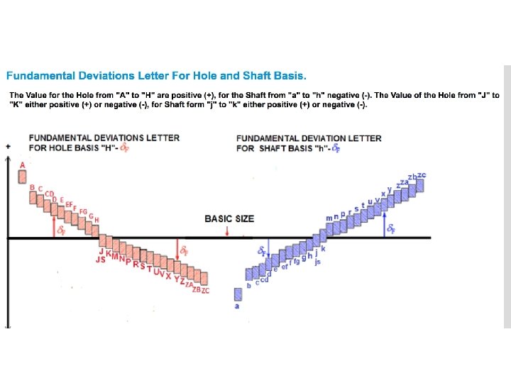
Terms related to Metric Limits & Fits Zero line
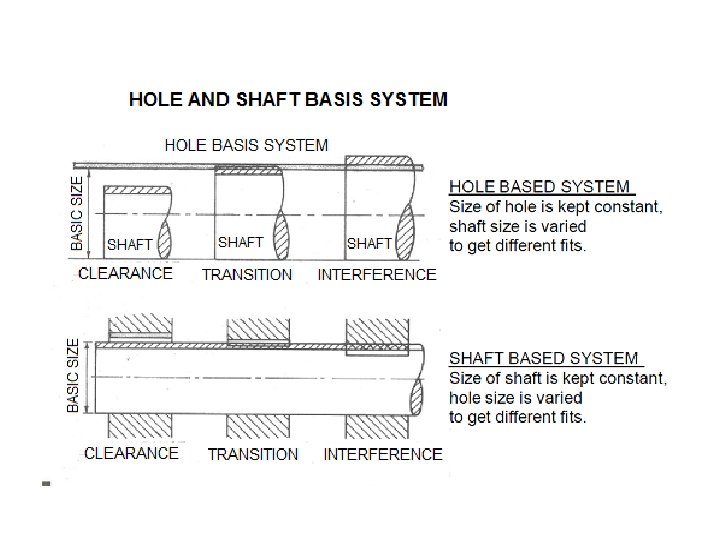
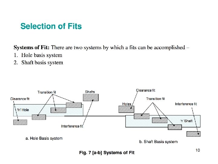
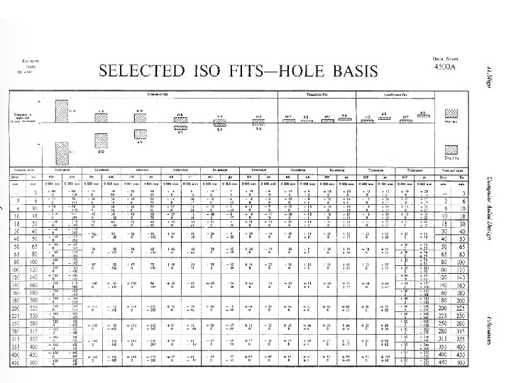
Hole & Shaft Basis System Hole Basis and Shaft Basis Systems To obtain the desired class of fits, either the size of the hole or the size of the shaft must vary. Two types of systems are used to represent the three basic types of fits, namely clearance, interference, and transition fits. They are (a) hole basis system and (b) shaft basis system. Although both systems are the same, hole basis system is generally preferred in view of the functional properties. Hole Basis System In this system, the size of the hole is kept constant and the shaft size is varied to give various types of fits. In a hole basis system, the fundamental deviation or lower deviation of the hole is zero, that is, the lower limit of the hole is the same as the basic size. The two limits of the shaft and the higher dimension of the hole are then varied to obtain the desired type of fit, as illustrated in Fig. 3. 13.
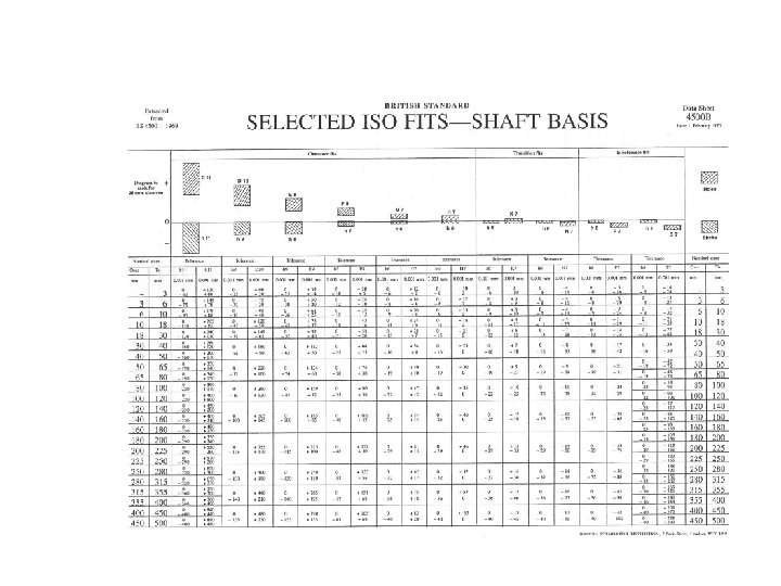
Shaft Basis System ü The system in which the dimension of the shaft is kept constant and the hole size is varied to obtain various types of fits is referred to as shaft basis system. ü In this system, the fundamental deviation or the upper deviation of the shaft is zero, that is, the HLH equals the basic size. The desired class of fits is obtained by varying the lower limit of the shaft and both limits of the hole, as shown in Fig. 3. 14.
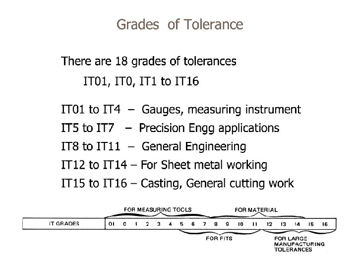
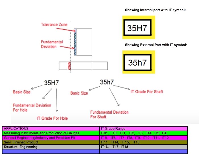
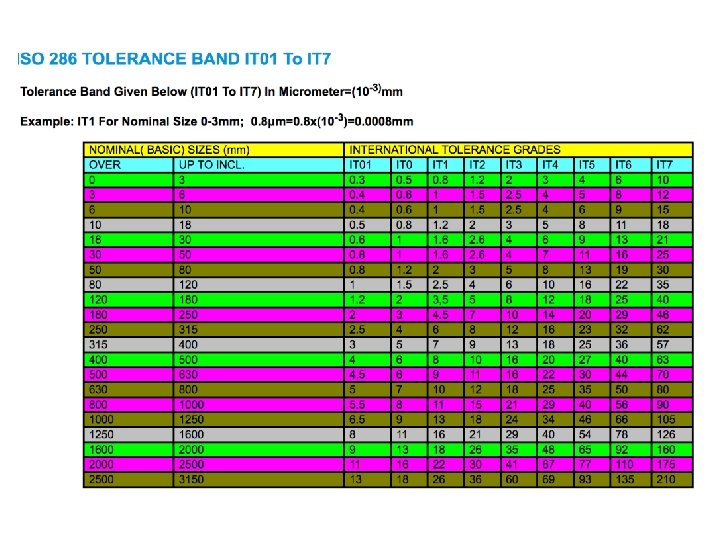
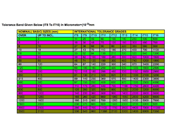
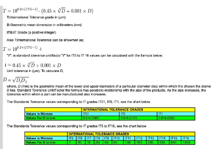
International Tolerance Grade IT grade is a group of tolerances. Each of the tolerances of this system is marked "IT" with attached grade of accuracy (IT 01, IT 0, IT 1. . . IT 16). IT Grades reference ISO 286.
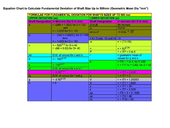
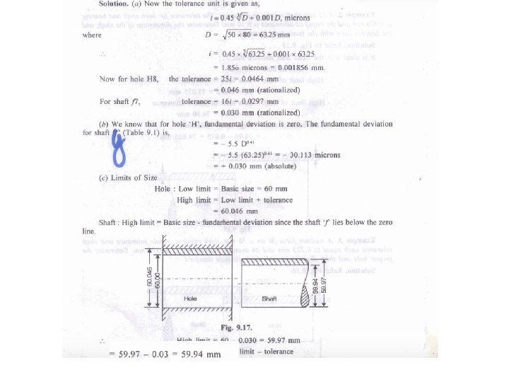
EXAMPLE: Lets chose the diameter of the shaft 60 mm, and Tolerance grade H 8 f 7; Calculation for Fundamental deviation, Tolerances and Limit of size for Hole and, Shaft. Calculation of the Standard tolerance Unit;