Ladder Diagram Introduction to PLC DMT 3533 Introduction


 is the standard")


 must always be located nearest the grounded power conductor")


")


- Slides: 49
Ladder Diagram Introduction to PLC DMT 353/3
Introduction • Programs for microprocessor based systems have to be loaded into them in machine code – sequence of binary number to represent the program instruction • Assembly language based on the use of mnemonic – e. g. LD to indicate the operation required to load data • Assembler is used to translate the mnemonics into machine code.
IEC 61131 -3 Standard • IEC 61131 -3 (International Electrotechnical Commission) is the standard of PLC programming language • Examples of PLC Programming language are; – – Ladder Diagrams Instruction List (like mnemonic) Structured Text (like C Programming) and Functional Block Diagrams.
Ladder Diagram • Ladder diagrams are specialized schematics commonly used to document industrial control logic systems. • They are called "ladder" diagrams because they resemble a ladder, with two vertical rails (supply power) and as many "rungs" (horizontal lines) as there are control circuits to represent. • If we wanted to draw a simple ladder diagram showing a lamp that is controlled by a hand switch, it would look like this:
Ladder Diagram • The left and right uprights represent power. If we connect the left and right uprights through a load, power can flow through the rung from the left upright to the right upright • Ladder logic diagrams are read from left-to-right, top-tobottom. • Rungs are sometimes referred to as networks
Ladder Diagram • The load(s) must always be located nearest the grounded power conductor in the ladder diagram • The PLC then runs the ladder and monitors the input continually and controls output. This called scanning
Ladder Diagram Symbols • The main function of PLC program is to control outputs based on the condition of inputs • The symbols used in ladder logic programming can be divided into two broad categories: – Contacts (inputs) and Coils (outputs)
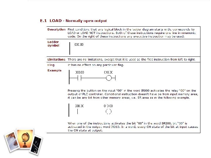
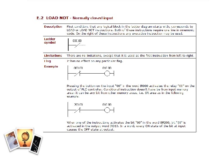
Contacts • Most inputs to a PLC are simple devices that are either on (true) or off (false). These inputs are sensors and switches that detect part presence, empty or full status, and so on. • Contacts can be thought of as switches. The two basic kinds of switches are normally open and normally closed: – A normally open switch does not pass current until it closed – A normally closed switch allows current flow until it closed
Contacts • Normally open switch won't conduct electricity until it is pressed down, and normally closed switch will conduct electricity until it is pressed. – E. g. doorbell and a house alarm. • Concepts normally open and normally closed can apply to sensors as well.
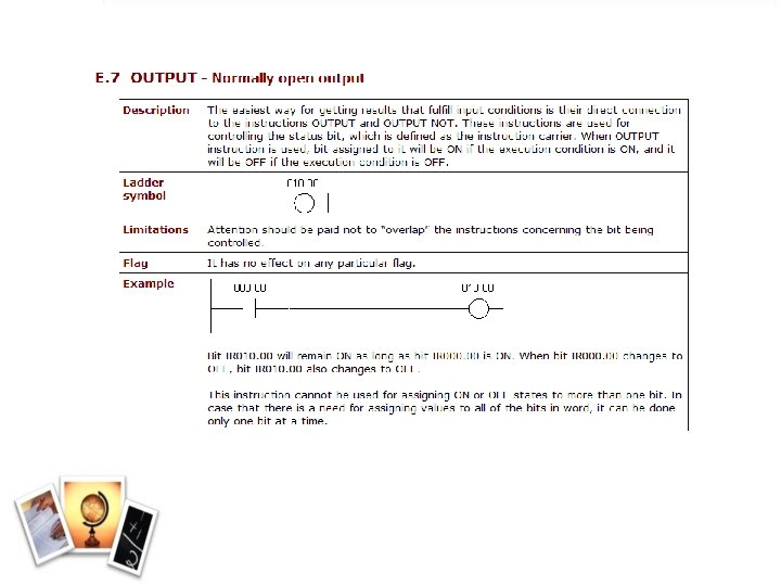
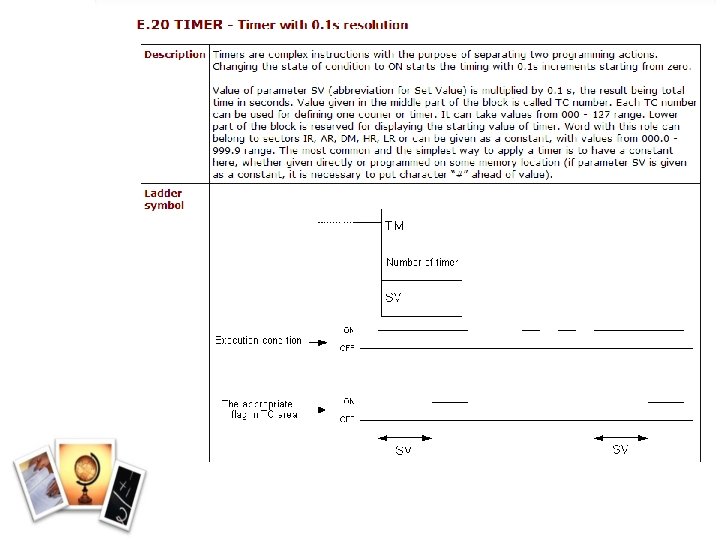
Coil • Coils are output symbols. There are many types of real-world output devices: motors, lights, pumps, counters, timers and relays • The PLC examines the contacts (inputs) in the ladder and turns the coils (outputs) on or off, depending on the condition of the inputs
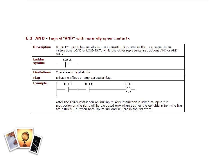
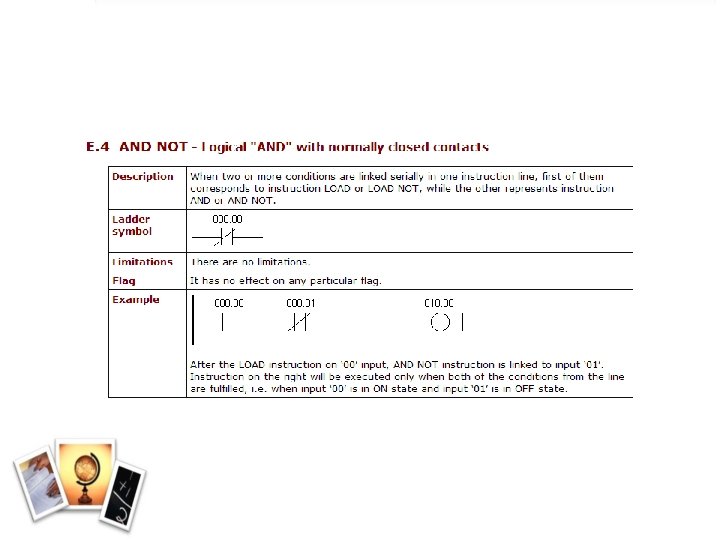
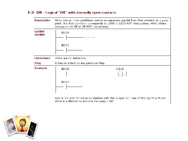
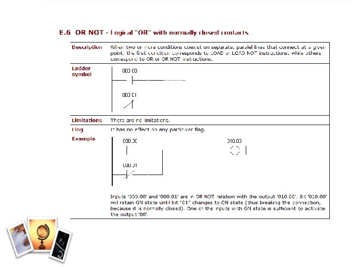
Basic Programming Instruction • Programmable control is based on the basic logic function (AND, OR, NOT) to form the instruction. • Parallel contacts are equivalent to an OR gate. • Series contacts are equivalent to an AND gate. • Normally-closed contacts are equivalent to a NOT gate (inverter).
Mnemonic Code • When using programming console, ladder diagram need to be converted into mnemonic code for entering the programming instructions. • The operand or data, is the item to be operated on by the operation. • Address is the memory storage location of the operand.
PLC Processor Memory Size The size of the programmable controller relates to the amount of user program that can be stored. The 1 K word memory size shown can store 1, 024 words, or 16, 380 (1, 024 x 16) bits of information using 16 -bit words or 32, 768 (1, 024 x 32) using 32 bit words.
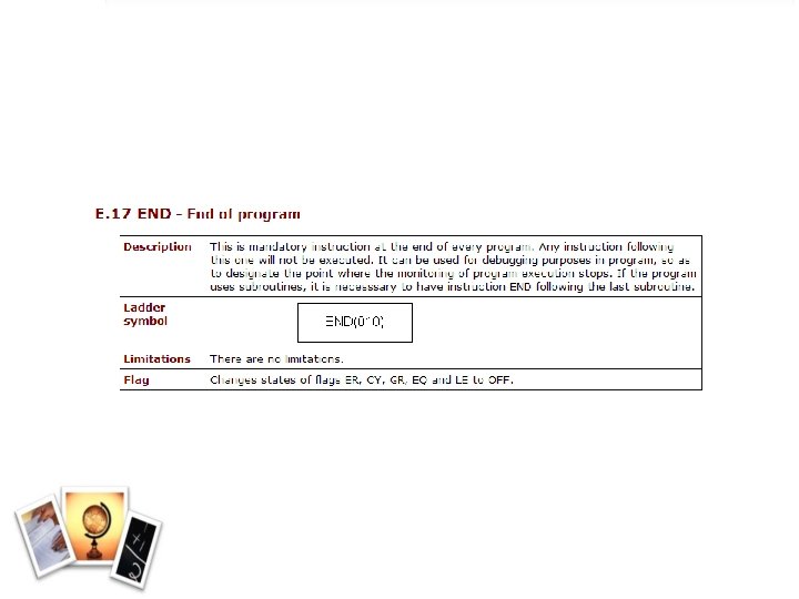
Instructions Description LD A starting instruction for logic line AND This is used to connect two or more inputs in serial OR This is used to connect two or more inputs in parallel AND LD This is used to connect two blocks in serial OR LD This is used to connect two blocks in parallel NOT invert its inputs Often used to form an NC (Normally Closed) input or output. NOT can be used with LD, OUT, AND or OR OUT This is used to connect output /designated operand bit END This is used to indicate the end of program. The last instruction in any program must be an END instruction.
AND Logic Function Address Instructions Data 00000 LD 000001 AND 00001 00002 AND NOT 00002 00003 OUT 01000 00004 END(01)
OR Logic Function Address Instructions Data 00000 LD 000001 OR 00001 00002 OR NOT 00002 00003 OUT 01000 00004 END(01)
Combining The Logic Functions 0001 0002 0004 0005 1000 Address 0003 END Instruction Data 0000 LD 0001 AND 0002 OR 0003 AND 0004 AND NOT 0005 OUT 1000 END(01)
AND LD 0001 0003 0002 0004 END 1000 Address Instruction Data 0000 LD 0001 OR 0002 LD 0003 OR NOT 0004 AND LD 0005 OUT 0006 END(01) 1000
OR LD 0001 0002 1000 Address 0003 0004 END Instruction Data 0000 LD 0001 AND 0002 LD 0003 AND NOT 0004 OR LD 0005 OUT 0006 END(01) 1000
Combining AND LD and OR LD Address 0001 0008 0002 0003 END 0004 0006 0005 0007 1000 Instruction Data 0000 LD 00001 AND NOT 00002 LD NOT 00008 0003 AND 00003 0004 OR LD 0005 LD 00004 0006 AND 00005 0007 LD 00006 0008 AND 00007 0009 OR LD 0010 AND LD 0011 OUT 0012 END(01) 1000
A Systematic Approach of Control System Design using a PLC 1. Determine the Machine Sequence of Operation • Decide what an equipment or system you want to control 2. Assignment of Inputs and Outputs • All external input and output devices to be connected to the PLC must be determined 3. Writing of the Program • Ladder diagram follows the control system sequence of operation as decided in step (1) 4. Programming into Memory 5. Running the System
Example
X 1 – start button FS – float switch C 1 – relay (in) S 1 – valve (in) T 2 – timer 90 s C 2 – relay (out) T 1 – timer 120 s S 2 – valve (out)
SELF READING
HARD WIRED VS
The term hardwired logic refers to logic control functions that are determined by the way devices are interconnected. Hardwired logic can be implemented using relays and relay ladder schematics. Hardwired logic is fixed: it is changeable only by altering the way devices are connected.
Example 1
Example 2
Example 3
Example 4
Example 5
Example 6
Example 7
Example 8
Example 9