KLEDU DLink Taiwan TTSS Name Phone 02 66000123


Unmanaged Switches-無任何管理功能 EX: DGS-1000系列 (2)Smart Switches—可透過web進行功能常用功能設定 EX: DGS-1200系列 (3)Smart Pro Switches—可透過web進行功能常用功能設定與簡易CLI")


 Standard Image (SI) ERPS (Ethernet Ring Protection")


![新建/移除帳號(CLI) create account [admin | operator | user] <username 15> delete account <username> show](https://slidetodoc.com/presentation_image_h/22422c53c05786e5a41b981f3629a2f1/image-26.jpg "新建/移除帳號(CLI) create account [admin | operator | user] <username 15> delete account <username> show")

![修改指令提示字眼 config command_prompt [<string 16> | username | default] <說明> <string 16> - 輸入一個不超過16個字元的字母數位元組合的字串來定義CLI](https://slidetodoc.com/presentation_image_h/22422c53c05786e5a41b981f3629a2f1/image-29.jpg "修改指令提示字眼 config command_prompt [<string 16> | username | default] <說明> <string 16> - 輸入一個不超過16個字元的字母數位元組合的字串來定義CLI")
![IP位址配置(CLI) config ipif <ipif_name 12> [{ipaddress <network_address> |vlan <vlan_name 32> |state [ enable |disable]}](https://slidetodoc.com/presentation_image_h/22422c53c05786e5a41b981f3629a2f1/image-30.jpg "IP位址配置(CLI) config ipif <ipif_name 12> [{ipaddress <network_address> |vlan <vlan_name 32> |state [ enable |disable]}")
![新增預設閘設定(CLI) create iproute [default ] <ipaddr> {<metric 1 -65535>} show iproute (顯示active可使用的routing) show iproute](https://slidetodoc.com/presentation_image_h/22422c53c05786e5a41b981f3629a2f1/image-31.jpg "新增預設閘設定(CLI) create iproute [default ] <ipaddr> {<metric 1 -65535>} show iproute (顯示active可使用的routing) show iproute")
 delete iproute default show iproute <說明> 移除一筆預設閘路由表 注意: 若設定完default route後, 使用show iproute要能夠顯示內容必須該ipif的 port是link")
![存檔 save {[config | log | all]} <說明> config – 使用該參數保存當前的交換機配置到NV-RAM log – 指定保存當前log資料至NV-RAM。](https://slidetodoc.com/presentation_image_h/22422c53c05786e5a41b981f3629a2f1/image-33.jpg "存檔 save {[config | log | all]} <說明> config – 使用該參數保存當前的交換機配置到NV-RAM log – 指定保存當前log資料至NV-RAM。")
 reboot {force_agree} <說明> force_agree 當指定force_agree時,不需要進一步確認立即執行重啟命令( 可不加此參數) 範例: DES-3700 -28: admin#reboot Command: reboot Are")
![顯示設定檔內容(CLI) show config [ current_config | config_in_nvram ] show config current_config include “<string>” <說明>](https://slidetodoc.com/presentation_image_h/22422c53c05786e5a41b981f3629a2f1/image-35.jpg "顯示設定檔內容(CLI) show config [ current_config | config_in_nvram ] show config current_config include “<string>” <說明>")


![SNTP Server (CLI) config time_zone {operator [+ | -] | hour <gmt_hour 0 -13>](https://slidetodoc.com/presentation_image_h/22422c53c05786e5a41b981f3629a2f1/image-42.jpg "SNTP Server (CLI) config time_zone {operator [+ | -] | hour <gmt_hour 0 -13>")
 show time (System clock) <說明> 此指令可顯示設備最近一次開機的時間與目前的時間 範例: DES-3700 -28: admin#show time Command:")
 show time (SNTP) <說明> 此指令可顯示設備最近一次開機的時間與目前的時間 範例: Down_3710 -12 C: 5#show time Command:")
 create syslog host <index 1 -4> ipaddress <ipaddr> {severity [informational |")
![Log儲存設定(CLI) config log_save_timing [time_interval <min 1 -65535> | on_demand | log_trigger] <說明> 交換器Log若不經過儲存的動作,設備重開後訊息將消失,透過 此功能可保全交換器log以利查測原因](https://slidetodoc.com/presentation_image_h/22422c53c05786e5a41b981f3629a2f1/image-47.jpg "Log儲存設定(CLI) config log_save_timing [time_interval <min 1 -65535> | on_demand | log_trigger] <說明> 交換器Log若不經過儲存的動作,設備重開後訊息將消失,透過 此功能可保全交換器log以利查測原因")
 設定路徑:System Configuration / System Log Configuration 1 4. 按下確定鍵. 2. 選擇儲存模式為Time Interval 5.")
![Ethernet介面設定(CLI) config ports <GE_portlist> | all ] {medium_type[fiber|copper]} { speed [auto | 10_half |](https://slidetodoc.com/presentation_image_h/22422c53c05786e5a41b981f3629a2f1/image-49.jpg "Ethernet介面設定(CLI) config ports <GE_portlist> | all ] {medium_type[fiber|copper]} { speed [auto | 10_half |")


")


: If receiving untagged frame, add")

 STP (Spanning Tree Protocol) Independent")


 PC發送封包的檢查順序 Routing table- ARP Table")
 Switch接收到封包後, 要轉送的檢查順序 Routing Table--> ARP Table - FDB Table Routing table")
 Switch接收到封包要轉送的檢查順序 Routing Table--> ARP Table - FDB Table ARP table")
 Switch接收到封包要轉送的檢查順序 Routing Table--> ARP Table - FDB Table FDB table")

 2 Host A 3 Ipif_10 10. 0. 0. 254/24")
 Ipif_10 10. 0. 0. 254/24 4 Host A 4.")
 Ipif_10 10. 0. 0. 254/24 Host A 7 8")


 show packet ports <portlist> <說明> 可顯示每個Port的Tx/Rx資料 範例:")
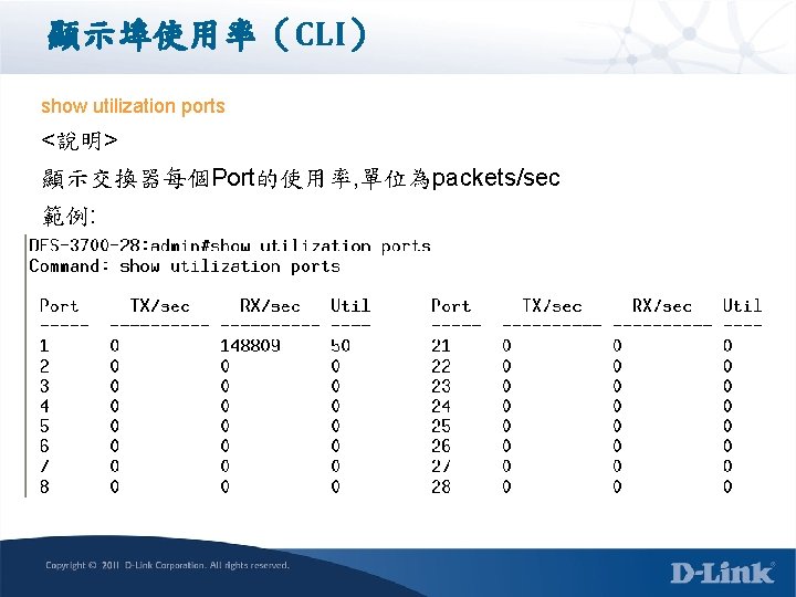
 <說明> 顯示交換器CPU每 5秒/1分鐘/5分鐘使用率 範例: DES-3700 -28: admin#show utilization cpu")

 show fdb {port <port> | vlan <vlan_name 32> | mac_address <macaddr> | static")

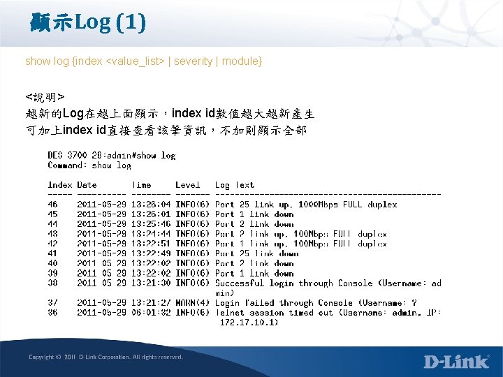
 show log severity [module | emergency | alert |critical |error | warning")
![Mirror功能(CLI) config mirror port <port> {[add | delete] source ports <portlist> [rx | tx](https://slidetodoc.com/presentation_image_h/22422c53c05786e5a41b981f3629a2f1/image-107.jpg "Mirror功能(CLI) config mirror port <port> {[add | delete] source ports <portlist> [rx | tx")


- Slides: 135
KL-EDU 網際網路教育訓練 D-Link Taiwan 友訊科技台灣分公司 TTSS 電信技術支援課 Name: Phone: 02 -66000123, Email:
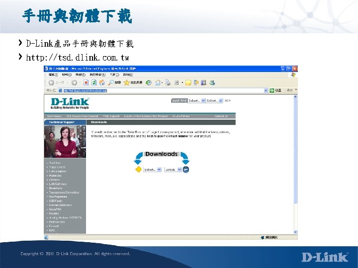
產品說明 D-Link產品資訊 http: //www. dlink. com. tw
D-Link Switch命名規則 EX: DES-3528 (24 port 10/100 M UTP+2 port 1 G combo+ 2 1 G UTP Port) 說明: (1)D-Link Fast. Ethernet Switch: 以 10/100 M為主要的Port, 搭配2 or 4 1 G uplink (2)3500系列的swith (5)28表示全部可同時使用的port為 28個 EX: DGS-3420 -28 TC (20 port 10/1000 UTP+4 1 G combo+4 10 G Fiber) 說明: (1)D-Link Gigi. Bit Switch: 以 1 GM為主要的Port, 搭配2 or 4 1 G or 10 G uplink (2)3420系列的swith (5)28表示全部可同時使用的port為 28個
D-Link Switch命名規則 DES-3528 DGS-3420 -28 TC combo
D-Link 交換器產品分類 SW產品線區分以下6種類型 (1)Unmanaged Switches-無任何管理功能 EX: DGS-1000系列 (2)Smart Switches—可透過web進行功能常用功能設定 EX: DGS-1200系列 (3)Smart Pro Switches—可透過web進行功能常用功能設定與簡易CLI EX: DGS-1500系列 (4)Stackable Smart. Pro Switches-支援 10 G堆疊與console介面與完整的CLI指 令支援 EX: DGS-1510系列 (5)Standard Managed Switches—具備CLI指令設定能力, 但功能較為低階 EX: DES-3000系列 (6)x. Stack Managed Switches--具備最完整功能的管理型交換器, 屬於高階機種 EX: DGS-3120/3420/3620
D-Link Switch 分類 DGS-3120 series F e a t u r e DGS-1510 series DGS-3000 series L 3 Managed Switch DGS-1500 series Stackable Smart. Pro Switch DGS-1210 series Smart. Pro Switch Web Smart Switch • • Multi-language GUI Compact CLIs SNMP v 1/v 2 c/3 D-View ACL Green v 3. 0 Po. E model • • Multi-language GUI Static Route Virtual stacking (SIM) 4 K VLAN groups RPS for Po. E model IPv 6 Ready Logo Phase II Green v 3. 0 2 x 10 G SFP+ Static Route Physical stacking Full featured CLIs RJ-45 console port 4 K VLAN groups Dual image Advanced security features • Do. S Attack Prevention • Green v 3. 0 • • P r i c e L 2 Managed Switch • RPS Support • DC Power • 6 k. V Surge & Lightning Protection • External Alarm Port (26 TC) • Advanced security features • L 2 PT • Q-in-Q • Outstanding Tripleplay support • OAM, ERPS • • L 3 Routing (EI/RI) Physical stacking Dual image Advanced security features OOB console Portable config/ image file Real time clock (RTC) OAM, ERPS
Entry Level L 2 GE Managed Switch Layer 3 802. 3 at DGS-3120 Series 24 TC/24 SC-DC/24 PC/48 TC/48 PC Release 2. 0 Release 2. 5 DLMS Ready DLMS SNTP for IPv 6 D-Link Green 3. 0 (SI) LBD v 4. 03 (SI) SMTP (SI) LLDP-MED (SI) L 3 Control Packet Filtering (SI) DDM (EI) IMPB 3. 91 (EI) 802. 3 ah Ethernet Link OAM (EI) WAC / JWAC for IPv 6 (EI) DHCPv 6 Client (EI) DHCPv 6 Relay Agent (EI) 802. 3 af DGS-3120 Series Rev. A 2 EEE Support Phase Out DGS-3100 series replaced by DGS-3120 series In Development DGS-3100 Series In Plan 24/24 P/48/48 P Q 4 / 2011 Available Q 1/ 2012 Q 2 / 2012 Q 3 / 2012
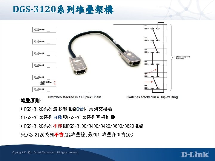
DGS-3120 SI & EI版本功能區分 Enhanced Image (EI) Standard Image (SI) ERPS (Ethernet Ring Protection Switching) 802. 1 D/1 w/1 s Spanning Tree Protocol LBD (Loop. Back Detection) 802. 3 ad Link Aggregation Port Mirroring IGMP/MLD Snooping GVRP 802. 1 Q Port/MAC-based VLAN IPv 6 Management Voice VLAN Private VLAN IPv 6 Neighbor Discovery (ND) 802. 1 p Bandwidth Control Co. S Based on IPv 6 Traffic Class ACL Time-based ACL/Po. E Co. S Based on IPv 6 Flow Label SSH/SSL Asymmetric VLAN ACL (Ingress / Egress / VLAN-based ACL) Traffic Segmentation DHCP Server Screening ACL Based on IPv 6 Traffic Class ARP Spoofing Prevention BPDU Attack Protection Port/Host Based 802. 1 X Port/Host Based WAC/MAC 1 Identity-driven security policy assignment Microsoft NAP Support SNMP, RMONv 1/v 2 LLDP ICMPv 6 DHCP Auto-configuration DHCP Relay 802. 3 ah Ethernet Link OAM IPv 6 Ready Logo Multiple images/configurations 802. 3 ah D-Link Extension: D-link Unidirectional Link Detection (DULD) Q-in-Q Static Route ARP Proxy ACL Based on IPv 6 Flow Label IP-MAC-Port Binding (IMPB) Compound Authentication s. Flow
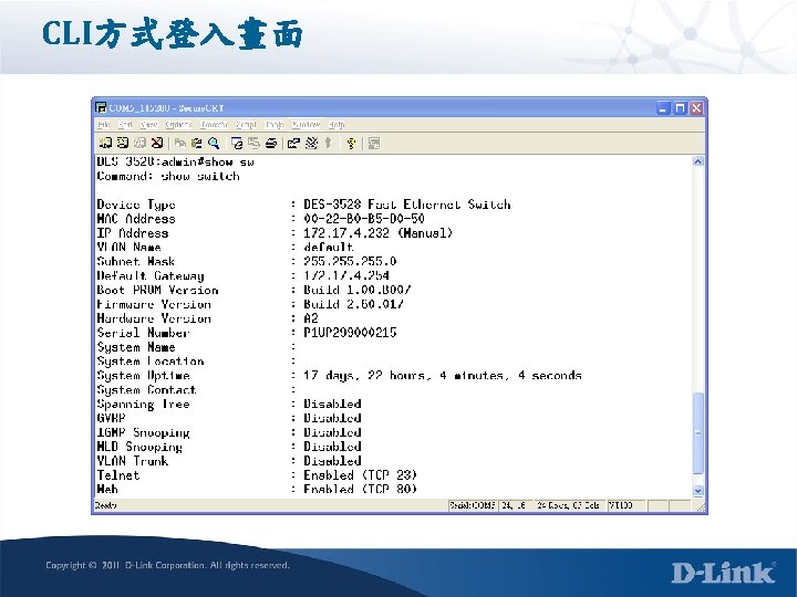
Access Switch 登入D-Link交換器預設並沒有帳號密碼 Default IP: 10. 90. 90 255. 0. 0. 0 Default Username : 空白 Default Password : 空白 可支援的連線方式: RS-232: baud rate 9600 or 115200 (新款交換器皆使用 115200) Telnet SSH HTTPS
指令語法說明 指令區分大小寫 TAB或是? 可以輔助完成與提示指令 範例: 使用? 號—列出所有動作可以接的指令 DES-3700 -28: admin#show ? Command: show Next possible completions: 802. 1 p accounting 802. 1 x acct_client access_profile account address_binding arp_spoofing_prevention arpentry attack_log 範例: 使用TAB---逐項由數字與A-Z顯示可接的指令 DES-3700 -28: admin#show 802. 1 p 指令執行完後, 出現Success字眼代表指令成功且立刻生效
新建/移除帳號(CLI) create account [admin | operator | user] <username 15> delete account <username> show account <說明> 用戶名為 1至 15個字元,密碼為 0至 15個字元,最多可以創建 8個用戶帳號。 範例: DES-3700 -28: admin#create account admin dlink Command: create account admin dlink Enter a case-sensitive new password: **** Enter the new password again for confirmation: **** Success. DES-3700 -28: admin#delete account dlink Command: delete account dlink Success.
既有帳號的密碼調整 config account <username> <說明> 用戶名為 1至 15個字元,密碼為 0至 15個字元,系統會提示先 鍵入舊密碼,之後再建立新密碼 範例: DES-3700 -28: admin#config account dlink Command: config account dlink Enter a old password: **** Enter a case-sensitive new password: **** Enter the new password again for confirmation: **** Success.
修改指令提示字眼 config command_prompt [<string 16> | username | default] <說明> <string 16> - 輸入一個不超過16個字元的字母數位元組合的字串來定義CLI 介面的命令提示。 username – 輸入該參數可以用交換機配置的登錄用戶名來替換當前的CLI命 令 default – 輸入該參數可以把命令提示變回出廠預設值。 範例: DES-3700 -28: admin#config command_prompt TPS 1 -DTMC Command: config command_prompt TPS 1 -DTMC Success. TPS 1 -DTMC : admin#
IP位址配置(CLI) config ipif <ipif_name 12> [{ipaddress <network_address> |vlan <vlan_name 32> |state [ enable |disable]} show ipif <說明> 針對設備管理IP進行調整, 注意ipif名稱有分大小寫, 預設名稱為System create vlan mgmt tag 4092 config vlan mgmt add tag 27 -28 config ipif System ipaddress 172. 16. 8. 79/24 vlan mgmt
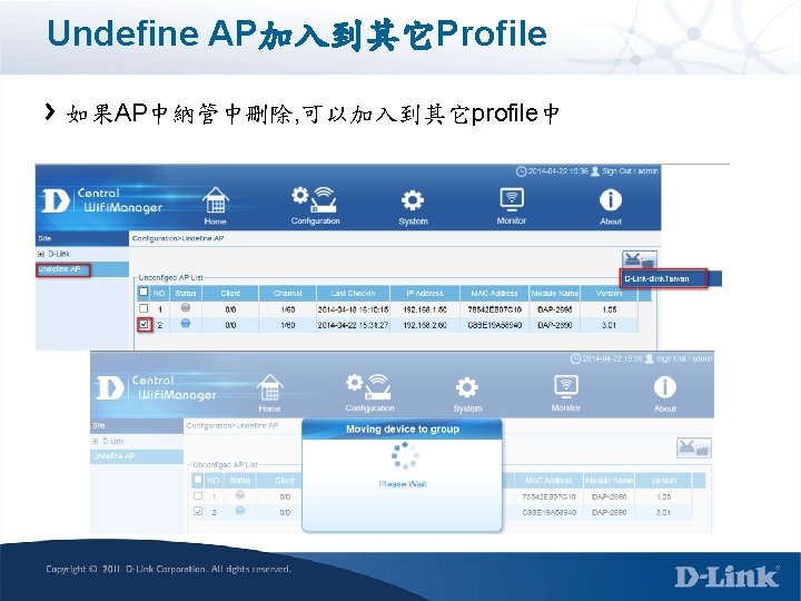
新增預設閘設定(CLI) create iproute [default ] <ipaddr> {<metric 1 -65535>} show iproute (顯示active可使用的routing) show iproute static (顯示static類型的routing) <說明> 建立一筆預設閘路由表 範例: DES-3700 -28: admin#create iproute default 10. 48. 74. 121 Command: create iproute default 10. 48. 74. 121 Success. 移除Default route delete iproute default
移除預設閘設定(CLI) delete iproute default show iproute <說明> 移除一筆預設閘路由表 注意: 若設定完default route後, 使用show iproute要能夠顯示內容必須該ipif的 port是link up狀態 範例: DES-3700 -28: admin#delete iproute default
存檔 save {[config | log | all]} <說明> config – 使用該參數保存當前的交換機配置到NV-RAM log – 指定保存當前log資料至NV-RAM。 all – 指定保存所有配置設置與log內容 範例: DES-3700 -28: admin#save all Command: save all Saving configurations and logs to NV-RAM. . . Done. .
重新開機(CLI) reboot {force_agree} <說明> force_agree 當指定force_agree時,不需要進一步確認立即執行重啟命令( 可不加此參數) 範例: DES-3700 -28: admin#reboot Command: reboot Are you sure you want to proceed with the system reboot? (y/n)y Please wait, the switch is rebooting. . .
顯示設定檔內容(CLI) show config [ current_config | config_in_nvram ] show config current_config include “<string>” <說明> 可顯示設備目前設定資料,另外透過include功能可快速篩選設定內容, 字串需要 加上雙引號 範例: show config current_config include “vlan”
升級韌體 download firmware_from. TFTP 10. 90. 99 DES-3528_v 10. had reboot
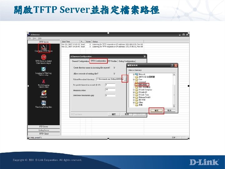
備份設定與還原 開啟TFTP Server, 並指定好路徑 備份設定檔 upload cfg_to. TFTP 192. 168. 1. 1 dest_file des-3552. cfg 回復設定檔 download cfg_from. TFTP 10. 90. 1 src_file des-3552. cfg save reboot
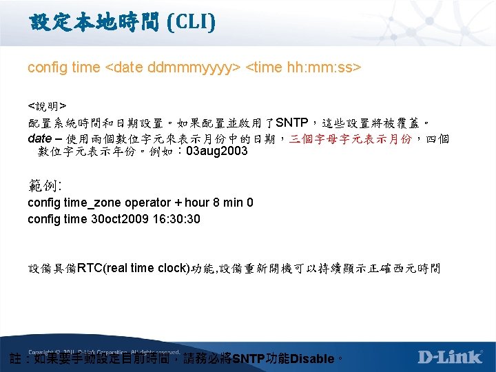
SNTP Server (CLI) config time_zone {operator [+ | -] | hour <gmt_hour 0 -13> | min <minute 0 -59>} config sntp {primary <ipaddr> | secondary <ipaddr> | poll-interval <int 3099999>} sec enable sntp <說明> 設定SNTP Server校時功能 範例: config time_zone operator + hour 8 min 0 config sntp primary 172. 19. 20. 250 secondary 0. 0 poll-interval 720 enable sntp 檢查設定 show sntp
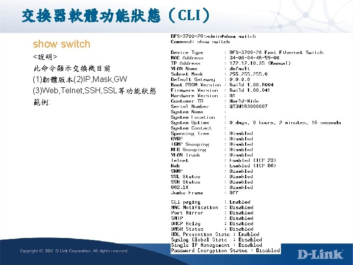
顯示設備開機時間 (CLI) show time (System clock) <說明> 此指令可顯示設備最近一次開機的時間與目前的時間 範例: DES-3700 -28: admin#show time Command: show time Current Time Source : System Clock Boot Time : 13 Oct 2009 21: 25: 47 Current Time : 13 Oct 2009 23: 57: 19 Time Zone : GMT +08: 00 Daylight Saving Time : Disabled Offset In Minutes : 60 Repeating From : Apr 1 st Sun 00: 00 To : Oct last Sun 00: 00 Annual From : 29 Apr 00: 00 To : 12 Oct 00: 00
顯示設備開機時間 (CLI) show time (SNTP) <說明> 此指令可顯示設備最近一次開機的時間與目前的時間 範例: Down_3710 -12 C: 5#show time Command: show time Current Time Source : Primary SNTP Server Boot Time : 13 May 2011 16: 26: 51 Current Time : 24 May 2011 14: 02: 00 Time Zone : GMT +08: 00 Daylight Saving Time : Disabled Offset In Minutes : 60 Repeating From : Apr 1 st Sun 00: 00 To : Oct last Sun 00: 00 Annual From : 29 Apr 00: 00 To : 12 Oct 00: 00
設定syslog Server (CLI) create syslog host <index 1 -4> ipaddress <ipaddr> {severity [informational | warning | all] | facility [local 0 | local 1 | local 2 | local 3 | local 4 | local 5 | local 6 | local 7] | udp_port <udp_port_number> | state [enable | disable] <說明> 藉由設定外部syslog server可將交換器發生事件導引至外部儲存備查,作為除 錯的資訊 可設定四組syslog server, 並可依據不同的severity送至不同的server 範例: enable syslog create syslog host 1 ipaddress 172. 17. 100 state enable 檢查設定 show syslog
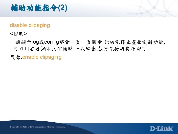
Log儲存設定(CLI) config log_save_timing [time_interval <min 1 -65535> | on_demand | log_trigger] <說明> 交換器Log若不經過儲存的動作,設備重開後訊息將消失,透過 此功能可保全交換器log以利查測原因 Default為on_demand 範例: config log_save_timing time_interval 60
Log儲存設定(WEB) 設定路徑:System Configuration / System Log Configuration 1 4. 按下確定鍵. 2. 選擇儲存模式為Time Interval 5. 將設定存檔. 3. 輸入時間單位(分鐘)
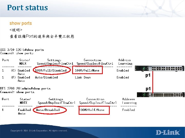
Ethernet介面設定(CLI) config ports <GE_portlist> | all ] {medium_type[fiber|copper]} { speed [auto | 10_half | 10_full | 100_half | 100_full | 1000_full{master|slave}] | flow_control [enable | disable] | learning [enable | disable ]| state [enable | disable ] | [description <desc 1 -32 > | clear_description]} show ports <說明> 針對Port調整速率與全半雙 或是用戶端描述 範例: DES-3700 -28: admin#config ports 1 speed 100_full
802. 1 Q vlan原理說明
Port based vlan v 10
Port based vlan 192. 168. 10. 2/24 P 1 -8 v 10 192. 168. 20. 2/24 P 9 -16 192. 168. 30. 2/24 P 17 -24 v 30 v 20 p 1 p 9 p 17 v 10 P 1 -8 192. 168. 10. 1/24 v 20 P 9 -16 v 30 P 17 -24 192. 168. 20. 1/24 192. 168. 30. 1/24
tag based vlan 192. 168. 10. 2/24 P 1 -8 v 10 192. 168. 20. 2/24 P 9 -16 192. 168. 30. 2/24 P 17 -24 v 30 v 20 tag 25 v 10 P 1 -8 192. 168. 10. 1/24 v 20 P 9 -16 v 30 P 17 -24 192. 168. 20. 1/24 192. 168. 30. 1/24
IEEE 802. 1 p/802. 1 q Frame Tagging The 32 -bit field (VLAN Tag) in the frame header that identifies the frame as belonging to a specific VLAN/priority. DA Data CRC Regular frame (or untagged frame) DA The Max. size of a Tagged Ethernet Frame is 1522 Bytes (1518+ 4 bytes tagging). SA Tagging Data CRC 802. 1 q/1 p tagged frame 8100 The frame without VLAN tag, we call it as Untagged Frame or Frame. SA 0 Priority CFI 15 18 19 Priority (1 p) has 3 bits, 0 -7. VLAN (1 q) has 12 bits, 0 -4095 VID 31
802. 1 p/1 q Untagged Incoming Frame Assumed the PVID of port 4 is 2 and default priority=0 The incoming untagged packet will be assigned to VLAN 2/priority=0 Port 5 is tagged and port 7 is untagged egress member of VLAN 2 This packet will be forwarded to port 5 and port 7 with tagged and untagged respectively. Priority tagging (802. 1 p) follows the similar rule as 802. 1 q tagging.
802. 1 p/1 q Untagged Incoming Frame The untagged packet is tagged as it leaves the switch through tagged port The VID is related to PVID of the incoming port The untagged packet is unchanged as it leaves the untagged port
802. 1 p/1 q Untagged Incoming Frame Assumed tagged incoming packet having vid=2/priority=0 Port 5 is a tagged and port 7 is an untagged egress member of VLAN 2 This packet will be forwarded to port 5 and port 7
802. 1 p/1 q Untagged Incoming Frame The tagged packet remains unchanged The tagged packet is stripped as it leaves the switch through untagged port
802. 1 p/1 q Tagging summary Ingress (incoming frame): If receiving untagged frame, add the tag into this frame with VID=PVID and priority= 802. 1 p default priority If receiving tagged frame, the VID/priority values are unchanged. Inside the Switch (all frames are tagged) For VLAN, based on the VID to lookup the VLAN table, and forward frame to member ports of this VLAN. For priority, based on the “Class of Service mapping” to process the frame with associated priority Queue. Egress (outgoing frame): Untagged egress port: Remove the tagging. Tagged Egress port: Un-change the tagging, so that the 1 p/1 q info can be carried to next 802. 1 p/q aware switch.
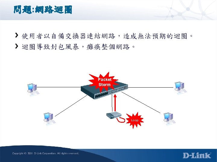
Loop detect
解決網路迴圈問題 D-Link解決方案:Loopback Detection ( LBD v 4. 04 ) STP (Spanning Tree Protocol) Independent 無網管型交換器不具備Spanning Tree Protocol功能。 D-Link交換器設計即使不開啟STP功能,亦可偵測出Loop。 LBD彈性設定,防止迴圈 Port-based VLAN-based V 1 V 2 PC 1 Loop PC 2 1. Port-based LBD - 連接埠關閉,無流量可通過。 2. VLAN-based LBD 依據發生迴圈的VLAN阻擋流量,該連接埠不關閉。
LBD迴圈偵測情境 Status A Status B Status C Loop
Loopdetect-Topology 1 Port based LBD PCB p 7 SW 1 p 5 Loop SW 2 PCA
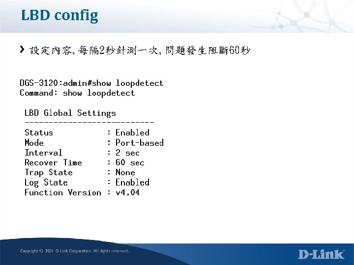
SW 1 config CLI config loopdetect mode port-based config loopdetect ports 1 -24 state enabled enable loopdetect config loopdetect interval 2 config loopdetect recover_timer 60 Check status show loopdetect ports all show log show ports
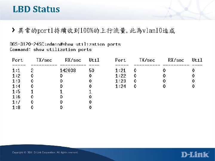
LBD Status 問題Port顯示Loop! Port狀態會顯示Err-Disabled
LBD Status Log記錄LBD發生與復原的時間
Loopdetect-Topology 2 Port based LBD PCB p 7 SW 1 p 3 p 5 Loop SW 2 PCA
LBD status 兩個Port會顯示Loop!
LBD status Port顯示Err-Disabled
LBD Status Log顯示內容
Loopdetect-Topology 3 PCB 100. 2 v 20 SW 1 p 1 SW 2 Loop p 2 v 10 v 20 SW 3 PCA 100. 1
SW 1 config create vlan v 10 tag 10 create vlan v 20 tag 20 config vlan default delete 1 -24 config vlan v 10 add untag 2 -4 config vlan v 20 add untag 5 -8 config vlan v 10 add tag 1 config vlan v 20 add tag 1 config loopdetect mode vlan-based config loopdetect ports 1 -24 state enabled enable loopdetect config loopdetect interval 2 config loopdetect recover_timer 60 save
SW 2 config create vlan v 10 tag 10 create vlan v 20 tag 20 config vlan default delete 1 -24 config vlan v 10 add untag 2 -4 config vlan v 20 add untag 5 -8 config vlan v 10 add tag 1 config vlan v 20 add tag 1 save
LBD status 採用vlan based, 會顯示異常的vlan id資訊
LBD Status Port 1依然會顯示Err-Disabled, 但沒有將實體Port關閉
LBD Status Log顯示特定vlan發生LBD問題
LBD Status Vlan 20的兩台PCB ping PCA, 正常沒有影響
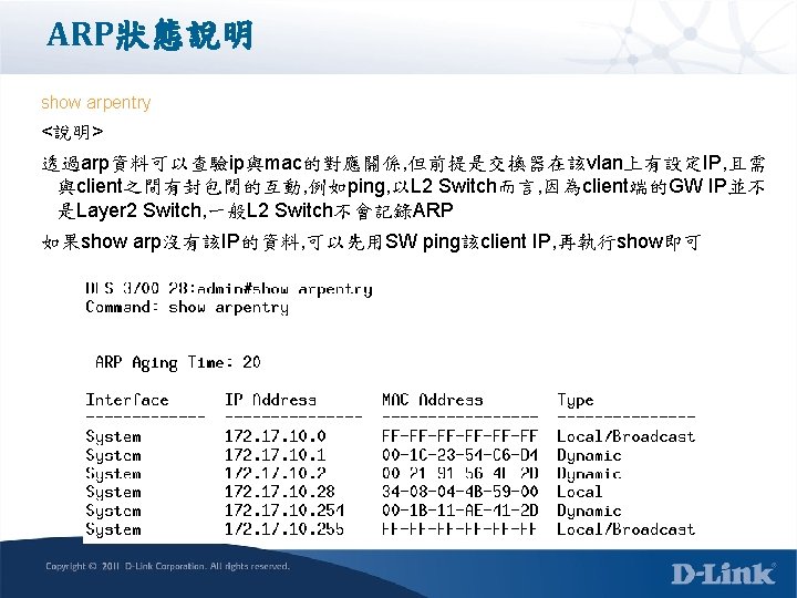
IP Routing Behavior 1. FDB Table: Record the VLAN, Port and MAC address mapping information. Uses for Layer 2 hardware forwarding. 2. ARP Table: Record the Local Host IP and MAC address mapping information. Uses to communicate with Local Host. 3. Routing Table: Record the Routing information from other networks. remote networks IP hardware routing. Uses for
Table比對順序(p 1) PC發送封包的檢查順序 Routing table- ARP Table
Table比對順序(p 2) Switch接收到封包後, 要轉送的檢查順序 Routing Table--> ARP Table - FDB Table Routing table
Table比對順序(p 2) Switch接收到封包要轉送的檢查順序 Routing Table--> ARP Table - FDB Table ARP table
Table比對順序(p 2) Switch接收到封包要轉送的檢查順序 Routing Table--> ARP Table - FDB Table FDB table
Layer 2 ARP Operations 1 Host A Network 10. 0/24 1. Host A need access Host B. 2. Host A broadcasts an Address Resolution Protocol (ARP) request. 3. If Host B is in the broadcast domain it responds with its MAC address. Host B Host A to Host B 2 Destination IP Host Address "B" Source Host IP Address "A" Source MAC Address "A" Destination MAC Address Broadcast Host B to Host A 3 Slide 87 Destination MAC Address "A" Source MAC Address "B" Source Host IP Address "B" Destination IP Host Address "A"
Layer 3 Routing Operations (1) 2 Host A 3 Ipif_10 10. 0. 0. 254/24 Ipif_20 20. 0. 0. 254/24 1. Host A need access Host B and host A check it’s routing table and arp table 2. Host A broadcasts an Address Resolution Protocol (ARP) request to L 3 ipif_10. 3. L 3 ipif_10 responds ARP with its MAC address. Host B ARP request 2 Destination IP Host Address “ipif_10" Source Host IP Address "A" Source MAC Address "A" Destination MAC Address Broadcast ARP response 3 Slide 88 Destination MAC Address "A" Source MAC Address “mac_10" Source Host IP Address “ipif_10" Destination IP Host Address "A"
Layer 3 Routing Operations (2) Ipif_10 10. 0. 0. 254/24 4 Host A 4. Host A send icmp packet to host B and the dest mac is mac_10 5. L 3 check the packet with it’s routing table and check it has the arp entry or not 6. L 3 ipif_20 broadcasts an Address Resolution Protocol (ARP) request to host B 5 6 Ipif_20 20. 0. 0. 254/24 Host B Host A to Host B 4 Destination IP Host Address “Host B" Source Host IP Address "A" Source MAC Address "A" Destination MAC Address “mac_10” ARP request 6 Slide 89 Destination MAC Address “B" Source MAC Address “mac_20" Source Host IP Address “ipif_20" Destination IP Host Address “B"
Layer 3 Routing Operations (3) Ipif_10 10. 0. 0. 254/24 Host A 7 8 7. Host B L 3 responds ARP with its MAC address. 8. L 3 ipif_20 send icmp packet to Host B. Ipif_20 20. 0. 0. 254/24 Host B ARP response 7 Destination IP Host Address “Host B" Source Host IP Address "A" Source MAC Address "A" Destination MAC Address “mac_10” Host A to Host B 8 Slide 90 Destination MAC Address “B" Source MAC Address “mac_20" Source Host IP Address “A" Destination IP Host Address “B"
Local IP Routing Net 1 Net 2 Net 3 Net 4 . 254 D-Link L 3 switch Server PC 1 PC 2 192. 168. 1. 1/24 PC 3 192. 168. 2. 1/24 Gw 192. 168. 1. 254 192. 168. 3. 1/24 Gw 192. 168. 2. 254 Gw 192. 168. 3. 254 192. 168. 4. 1/24 Gw 192. 168. 4. 254 Objective: Different IP Interface can routed in a stand alone device without any Layer 3 protocol Enable. Principle: L 3 switch will create 4 local routes in the Routing table. Packets to the different subnet will be routed based on the routing table.
Local IP Routing範例說明 PROCDEURE: 1. Delete ports from default vlan for other vlan use. config vlan default delete 1 -24 2. Create VLAN, add ports into it, and then create IP interface for the VLAN. create vlan v 101 tag 101 config vlan v 101 add untagged 1 -6 create ipif net 1 192. 168. 1. 254/24 v 101 state enable create vlan v 102 tag 102 config vlan v 102 add untagged 7 -12 create ipif net 2 192. 168. 2. 254/24 v 102 state enabled create vlan v 103 tag 103 config vlan v 103 add untagged 13 -18 create ipif net 3 192. 168. 3. 254/24 v 103 state enabled create vlan v 104 tag 104 config vlan v 104 add untagged 19 -24 create ipif net 4 192. 168. 4. 254/24 v 104 state enabled save 3. Check if IP interfaces are correctly configured. show vlan show ipif At Client PC 1. 2. Manually configure IP address, mask, for the associated IP Network. Gateway = L 3 switch’s Interface IP
跨設備的IP Routing—static route 192. 168. 5. 254/24 192. 168. 5. 253/24 SW 1 192. 168. 1. 253/24 192. 168. 1. 254/24 SW 1 SW 2. 254 PC 1 PC 2 192. 168. 1. 1/24 PC 3 Gw 192. 168. 1. 254 192. 168. 2. 1/24 192. 168. 3. 1/24 Gw 192. 168. 2. 254 Gw 192. 168. 3. 254 Server 192. 168. 4. 1/24 Gw 192. 168. 4. 254
設備的IP Routing---static route SW 1 create iproute default 192. 168. 5. 254 create iproute 192. 168. 2. 0/24 192. 168. 1. 254 create iproute 192. 168. 3. 0/24 192. 168. 1. 254 create iproute 192. 168. 4. 0/24 192. 168. 1. 254 save SW 2 create iproute default 192. 168. 1. 253 save
Troubleshooting
Error status show error ports 1 <說明> 檢視每個Port在ethernet端的錯誤封包統計 Half mode這端會因為流量多時而出現collision統計 Full mode這端會有CRC產生 Half mode port p 1
顯示封包數量(CLI) show packet ports <portlist> <說明> 可顯示每個Port的Tx/Rx資料 範例:
顯示CPU使用率(CLI) <說明> 顯示交換器CPU每 5秒/1分鐘/5分鐘使用率 範例: DES-3700 -28: admin#show utilization cpu
Layer 2 Data link layer 第二層除錯 1. Vlan的port配置錯誤/untag/tag測試錯誤 2. Vlan id設定錯誤 3. Spanning tree封鎖 4. Protocol vlan配置錯誤 show fdb show vlan show port dot 1 v show stp ports show vlan_counter
檢視MAC位址(CLI) show fdb {port <port> | vlan <vlan_name 32> | mac_address <macaddr> | static | aging_time} <說明> port <port> 與目的MAC目的地址相對應的埠號。 <vlan_name 32> MAC地址所在的VLAN名稱。 <macaddr> 轉發資料庫表中顯示的MAC位址。 static 顯示靜態MAC位址條目。 aging_time 顯示MAC位址轉發資料庫的存在時間。 範例: show fdb
Vlan狀態 show vlan <說明> 檢視valn id, port untag/tag是否正確
顯示Log (2) show log severity [module | emergency | alert |critical |error | warning | notice |informational debug] <說明> 在log相當多的情況下, 可以透過severity的功能先查看是否有嚴重性的Log出現, 以及 出現的時間來對照問題發生的時間點 範例: show log severity critical
Mirror功能(CLI) config mirror port <port> {[add | delete] source ports <portlist> [rx | tx | both]} enable mirror <說明> Mirror功能可複製特定port的雙向流量, 導出目的Port以分析封包內容除錯 範例: 將port 2 -5雙向的流量送至Port 1內的分析軟體 config mirror port 1 add source ports 2 -5 both enable mirror
可檢視設備硬體狀況 show environment
Device check show device
CWM
Login Page http: //210. 240. 1. 119
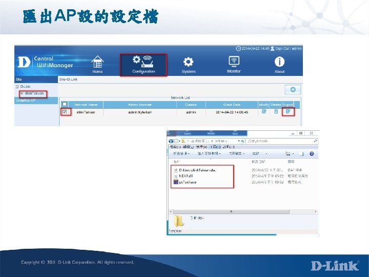
CWM Add Site
CWM Add Site Network Name
Configuration dlink. Taiwan Add SSID
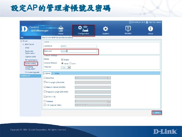
設定 2. 4 GHz Primary SSID名稱及加密方式
設定 5 GHz Primary SSID名稱及加密方式
設定 2. 4 GHz SSID 1 WPA 2 -Enterprise
設定 5 GHz SSID 1 WPA 2 -Enterprise
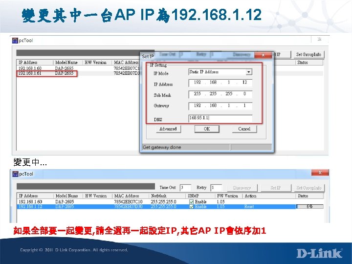
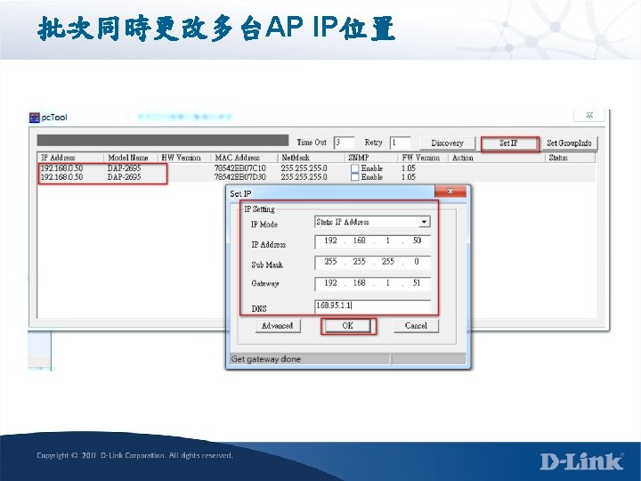
pctool 使用方式 internet DFL-260 E 192. 168. 1. 1/24 Switch L 2 NB AP 1 AP 2 CWM Server 220. 135. 83. 30
RF Optimization
Online Client IP Alias
Q&A Thank you