CHAPTER 5 CIRCUIT THEOREMS CIRCUIT THEOREMS Source Transformation


 and (2): V 1 V 2")


 For mesh 1 For mesh 2")

 For mesh 1 For mesh 2")


")


")


 • Use superposition principle to determine the voltage Vo.")


- Slides: 114
CHAPTER 5 CIRCUIT THEOREMS
CIRCUIT THEOREMS • • • Source Transformation Thevenin’s Theorem Norton’s Theorem Maximum Power Transfer Superposition
SOURCE TRANSFORMATION Source Transformation is the process of replacing a voltage source vs series with a resistor R by a current source is in parallel with a resistor R, or vice versa Note: The arrow of the current source is directed toward the positive terminal of the voltage source
Example…
Source transformation procedure From To method Use,
From To method Use,
EXAMPLE Determine ix ix
ix
ix
EXAMPLE Use source transformation to reduce the circuit to a single voltage source in series with a single resistor
EXERCISE 1 Use source transformation to find i Ans: i=555. 5 m. A
EXERCISE 2 Use source transformation to determine the current and power absorbed by 8Ω resistor Ans: i=1 A P = 8 W
CIRCUIT THEOREMS • • • Source Transformation Thevenin’s Theorem Norton’s Theorem Maximum Power Transfer Superposition
THEVENIN EQUIVALENT CIRCUIT • Thevenin’s theoram states that a linear twoterminal circuit can be replaced by an equivalent circuit. • Thevenin equivalent circuit consist of an independent voltage source, VTh in series with a resistor RTh. Original circuit Thevenin equivalent circuit
Thevenin equivalent circuit:
• Thevenin voltage, VTh = open circuit voltage in the original circuit. • Thevenin resistance, RTh is the ratio of open-circuit voltage to the short-circuit current.
Step 1: Disconnect the load, RL Step 2: Find Thevenin’s Resistance, RTH Step 3: Find Thevenin’s Voltage, VTH Step 4: Determine the voltage across the load or current through it.
Detail Procedures: 1. Remove the load from the circuit. 2. Label the resulting two terminals. We will label them as a and b, although any notation may be used. 3. Set all sources in the circuit to zero. Voltage sources are set to zero by replacing them with short circuits (zero volts). Current sources are set to zero by replacing them with open circuits (zero amps).
4. Determine the Thévenin equivalent resistance, RTH, by calculating the resistance “seen” between terminals a and b. It may be necessary to redraw the circuit to simplify this step. 5. Replace the sources removed in Step 3, and determine the open-circuit voltage between the terminals. The resulting open-circuit voltage will be the value of the Thévenin voltage, VTH.
6. Draw the Thévenin equivalent circuit using the resistance determined in Step 4 and the voltage calculated in Step 5. As part of the resulting circuit, include that portion of the network removed in Step 1.
FINDING VTH Thevenin voltage, VTh = open circuit voltage in the original circuit.
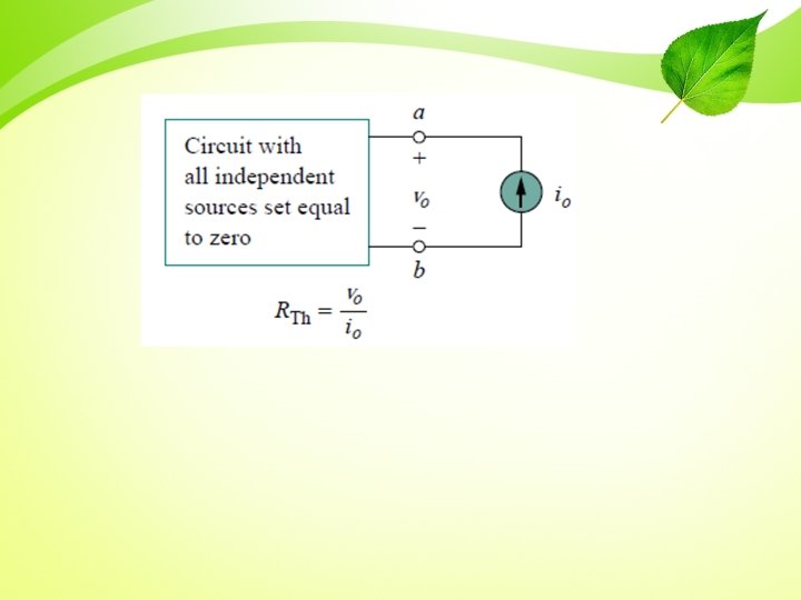
FINDING RTH Case 1: If the network has no dependent sources, we turn off all independent sources. RTh is the input resistance of the network looking between terminals a and b.
FINDING RTH Case 2: If the network has dependent sources, we turn off all independent sources. Dependent sources are not to be turned off because they are controlled by circuit variables. We apply a voltage source vo at terminals a and b and determine the resulting current io. Then:
Or Alternatively, we may insert a current source io at terminals a-b as shown in Fig 2 and find the terminal voltage vo. Again: Either of the two approaches will give the same result. In either approach we may assume any value of vo and io. For example, we may use vo = 1 V or io = 1 A, or even use unspecified values of vo or io.
FINDING RTH Thevenin’s resistance can also be determined by placing a short circuit across the output terminals and finding the current through the short circuit.
Thevenin’s equivalent circuit
Example
STEP 1: To find VTH Using node-voltage method for open-circuit:
STEP 2: To find RTH Short-circuit condition at terminal a-b
Using Node-voltage method for short-circuit:
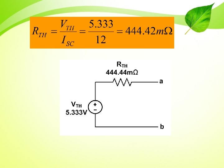
Short-circuit current: Thevenin resistance:
Thevenin equivalent circuit
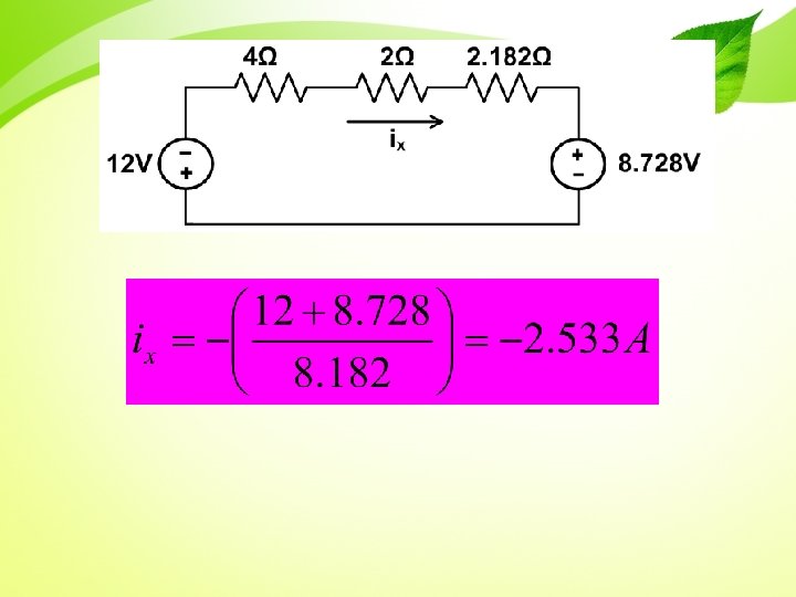
EXAMPLE Using Thevenin theoram, find the equivalent circuit to the left of the terminals in the circuit in circuit below. Then find I
STEP 1: To find RTH Voltage source, 12 V Current source 2 A Short circuit Open circuit
STEP 2: To find VTH Supermesh equation At circuit Solve equation
VTH is equal to the voltage at 4Ω resistor Thevenin equivalent circuit
THEVENIN EQUIVALENT CIRCUITCircuit with dependent source 1. Find VTH 2. Find RTH METHOD 1: Step 1: turn off all independent sources. Step 2: Excite the circuit with either a 1 V voltage source or a 1 A current source Step 3: Find the current Io through 1 V voltage source/ voltage Vo across 1 A current source Step 4: METHOD 2: Step 1: Place a short circuit across the output terminals and find the current, ISC through the short circuit. Step 2:
EXAMPLE Obtain the Thevenin equivalent of the circuit
• Since there is no independent sources, value of VTH = 0 V • You will only have to find RTH • STEP 1: Excite the circuit with either a 1 V voltage source or a 1 A current source • STEP 2: Find Vo or Io • STEP 3:
• STEP 1: Excite the circuit with either a 1 V voltage source or a 1 A current source
• STEP 2: Find Vo or Io • Using mesh analysis, • From circuit, • and • Substitute in to equation at loop 1
• STEP 3:
EXAMPLE Find the Thevenin equivalent circuit
To find RTH: METHOD 1 KCL at node V 1: V 1 V 2
KCL at node V 2: Solve equation (1) and (2): V 1 V 2
To find RTH: METHOD 2 To find VTH: Using node-voltage method V + VTH - From the circuit:
To find ISC: Using node-voltage method V ISC
EXERCISE 1 Apply Thevenin theorem to find Vo Ans : RTH=5Ω VTH= 19. 2 V Vo=12. 8 V
EXERCISE 2 Obtain Thevenin equivalent Ans : RTH=0. 4762Ω VTH= 1. 9841 V
EXERCISE 3 Find Thevenin equivalent at terminal ab and solve for ix Ans : RTH=10Ω VTH= 0 V ix=0 A
CIRCUIT THEOREMS • • • Source Transformation Thevenin’s Theorem Norton’s Theorem Maximum Power Transfer Superposition
NORTON EQUIVALENT CIRCUIT • A Norton equivalent circuit consists of an independent current source, IN in parallel with the Norton equivalent resistance, RN. • Can be derive from a Thevenin equivalent circuit simply by making a source transformation. • Norton current, IN = the short-circuit current at the terminal of interest. • Norton resistance, RN = Thevenin resistance, RTh
Norton equivalent circuit Norton current, IN is the short circuit current flowing from terminal a and b
EXAMPLE Find the Norton equivalent circuit of the circuit shown below
To find RN Current source 2 A Voltage source 12 V Open circuit Short circuit
To find IN (a) For mesh 1 For mesh 2
Solve the equation
To find IN (b) For mesh 1 For mesh 2
Solve the equation VTH is equal to voltage at 5Ω
Norton equivalent circuit
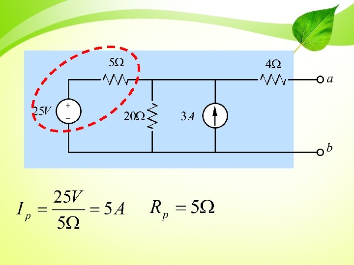
EXAMPLE Find Norton equivalent circuit
Step 1: Source transformation
Step 2: Parallel sources and parallel resistors combined Series resistor combined
Step 3: Source transformation, series resistors combined, producing the Thevenin equivalent circuit THEVENIN EQUIVALENT CIRCUIT
Step 4: Source transformation, producing the Norton equivalent circuit NORTON EQUIVALENT CIRCUIT
EXERCISE 1 • Find the Norton equivalent with respect to terminal a-b Ans: RN=10Ω IN= 666. 67 m. A
EXERCISE 2 • Obtain Norton equivalent of the circuit below to the left of terminal a-b. Use the result to find current i Ans: RN=10Ω IN= -0. 4 A i= 2. 4 A
CIRCUIT THEOREMS • • • Source Transformation Thevenin’s Theorem Norton’s Theorem Maximum Power Transfer Superposition
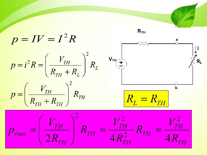
MAXIMUM POWER TRANSFER • Two basic types of system: – Emphasizes the efficiency of the power transfer – Emphasizes the amount of power transferred.
• Maximum power transfer is a technique for calculating the maximum value of p that can be delivered to a load, RL. • Maximum power transfer occurs when RL=RTh. Maximum power theorem
Maximum power theorem Maximum power is transferred to the load when the load resistance equals the Thevenin resistance as seen form the load
CIRCUIT THEOREMS • • • Source Transformation Thevenin’s Theorem Norton’s Theorem Maximum Power Transfer Superposition
SUPERPOSITION PRINCIPLE • In a circuit with multiple independent sources, superposition allows us to activate one source at a time and sum the resulting voltages and currents to determine the voltages and currents that exist when all independent sources are activate. • The superposition principle states that the voltage across (or current through) an element in a linear circuit is the algebraic sum of the voltage across (or current through) that element due to each independent source acting alone
Step of Superposition principle 1. Deactivated all the sources and only remain one source at one time. Do circuit analysis to find voltages or currents. 2. Repeat step 1 for each independent sources. 3. Sum the resulting voltages or currents.
REMEMBER!!! 1. Independent voltage source will become short-circuit with 0Ω resistance. 2. Independent current source will become open-circuit. 3. Dependent sources are never deactivated when applying superposition.
Example… Find Vo
• Step 1: deactivated all sources except voltage source
• V 0 is calculated using voltage divider:
• Step 2: Deactivated all sources except current source
• V 0 is calculated by using current divider:
• Step 3: Sum all the resulting voltages: V 0 =2+5=7 V.
EXAMPLE Find io in the circuit below using superposition
STEP 1: Deactivate all independent source except 4 A current source and find I’o
STEP 2: Deactivate all independent source except 20 V voltage source and find i’’o
STEP 3: Sum all the resulting currents
EXERCISE 1 • Using superposition find V in the circuit below V=4. 1538 V
EXERCISE 2 Use superposition to find vo Vo=7 V
Question 3 (thevenin)
• Open-circuit voltage, Voc:
• Node-voltage equation for Voc
• Thevenin resistance, RTh:
• Thevenin equivalent circuit:
Question 4 (norton)
• Open-circuit current, Isc:
• Norton resistance, RN: RN = 4Ω
• Norton equivalent circuit:
Question 5 (superposition) • Use superposition principle to determine the voltage Vo.
• Deactivated current source
• Deactivated voltage source
• Summing the voltage V 0
PRACTICE 1 Find the Thevenin equivalent circuit of the circuit shown in figure below, to the left of the terminals a-b. Then find the current through RL = 6, 16, and 36Ω. Ans: RTH = 4Ω VTH = 30 V IL = 3, 1. 5, 0. 75 A.
PRACTICE 2 Find the Thevenin equivalent of the circuit in figure below. Ans: RTH = 6Ω VTH = 20 V
PRACTICE 3 Find the Norton equivalent circuit for the circuit in figure below. Ans: RN= 3Ω IN= 4. 5 A
PRACTICE 4 Using Norton’s theorem, find RN and IN of the circuit in figure below at terminals a -b. Ans: RN= 1. 67Ω IN= 6 A
PRACTICE 5 Find the Norton equivalent circuit of the circuit in figure below. Ans: RN= 1. Ω IN= 10 A
PRACTICE 6 Find the value of RL for maximum power transfer in the circuit of figure below. Find the maximum power. Ans: RL= 9Ω Pmax= 13. 44 W
PRACTICE 7 Determine the value of RL that will draw the maximum power from the rest of the circuit in figure below. Calculate the maximum power. Ans: RL= 4. 22Ω Pmax= 2. 901 W
PRACTICE 8 Using the superposition theorem, find vo in the circuit in figure below. Ans: Vo= 12 V
PRACTICE 9 Use superposition to find vx in the circuit in figure below. Ans: Vx= 12. 5 V