Chapter 2 DC Circuit Theorem Circuit Analysis Introduction


. Calculate voltage across the")


. Calculate voltage across the")
")


 2. Combine the 4Ω and 2Ω resistors in series and transform")


 an element")


- Slides: 32
Chapter 2 DC Circuit Theorem & Circuit Analysis
Introduction n Circuit theorems: q q n Thevenin’s Theorem Norton’s Theorem Techniques for circuit analysis: q q Nodal analysis Mesh analysis Source transformation technique Superposition technique
Circuit Theorem Thevenin’s & Norton’s Theorems • To simplify complicated circuit consists of resistors and voltage source or current source into simple circuit. • Thevenin’s Theorem : Simplify complicated circuit into simple circuit consists single voltage source and single resistor connected in series. • Norton’s Theorem : Simplify complicated circuit into simple circuit consists single current source and single resistor connected in parallel.
Thevenin’s Theorem Thevenin’s theorem states that a linear two–terminal circuit can be replaced by an equivalent circuit consisting of a voltage source VTh in series with a resistor RTh. VTh is the open circuit voltage at the terminals. RTh is the input or equivalent resistance at the terminals when the independent sources are turned off. Outside network Complicated circuit consisting of resistors and voltage source Thevenin’s equivalence circuit
Thevenin’s Theorem Step 1 : Disconnect the Outside Network (Load). Calculate voltage across the open circuit, VTh For example : Calculate or measure VTh No current flow → VTh
Thevenin’s Theorem Step 2 : Set Independent source to zero. Measure resistance, RTh at a-b. For a voltage source v, set v = 0 and replace the voltage source by a short circuit. For a current source i , set i = 0 and replace the current source by an open circuit. For example : RTh
Example 1 Obtain the Thevenin equivalent voltage, VTh and equivalent resistance, RTh at terminal a-b for below circuit. Source: DNT 113 Midterm 2013 Q 2(b)
Answer RTh i 1 i 2 VTh
Norton’s Theorem Norton’s theorem states that a linear two-terminal circuit can be replaced by an equivalent circuit consisting of a current source IN in parallel with a resistor RN. IN is the short circuit consisting of a current through the terminals. RN is the input or equivalent resistance at the terminals when the independent sources are turned off. Norton equivalence circuit consisting of IN and RN.
Norton’s Theorem Step 1 : Disconnect the Outside Network (Load). Calculate voltage across the open circuit, VTh (Same method as to find VTh in Thevenin’s theorem) Step 2 : Take-out Voltage / Power source and replace by short circuit. Measure RN. (Same method as to find RTh in Thevenin’s theorem) Step 3 : Calculate IN using Ohm’s Law.
Example 2 Answer: Calculate VRL (Answer : 1. 61 V)
Application of Kirchhoff’s Law Two powerful techniques for circuit analysis: 1. Nodal analysis ( application of KCL) 2. Mesh analysis ( application of KVL)
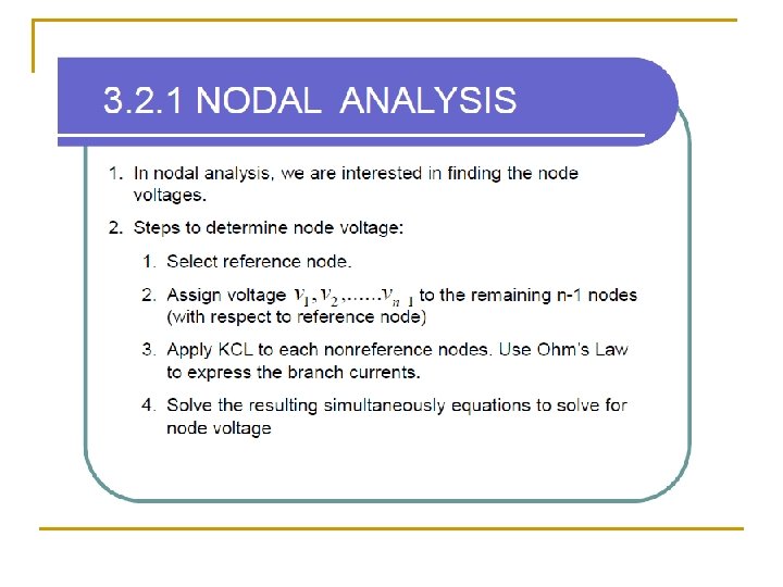
3. 2. 2 NODAL ANALYSIS
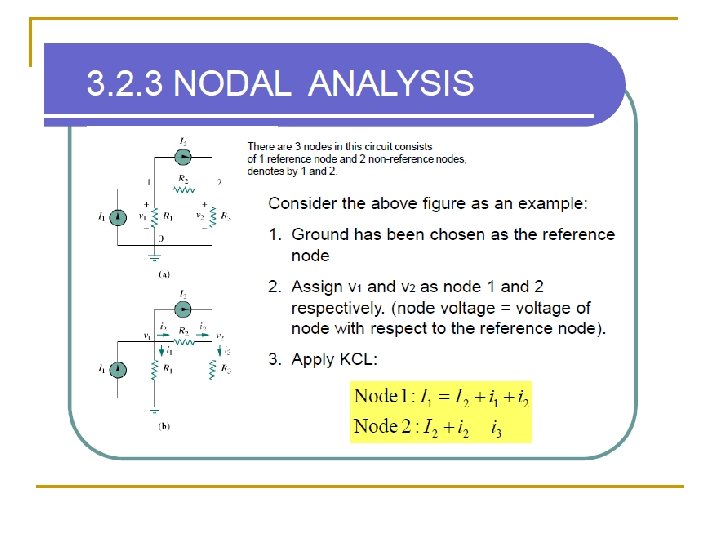
3. 2. 4 NODAL ANALYSIS
Example 3 Determine the current i 2 that flow through Resistor 3.
Answer Determine the current i 2 that flow through Resistor 3. v 0 i 4 i 3 i 1 v 0
Example 4 Write the mesh-current equations for below circuit and determine I 1, I 2 and I 3.
3. 4. 10 b MESH ANALYSIS Solution: Write mesh-current equations : Simplify the equations : Solve above simultaneous equations :
Source Transformation A source transformation is the process of replacing a voltage source Vs in series with a resistor R by a current source Is in parallel with a resistor R, or vice versa. Source transformation is another tool for simplifying circuits. For example to transform series-parallel circuit and Y – delta circuit. Basic to these tools is the concept of equivalence. Thevenin’s equivalence circuit Norton’s equivalence circuit
Source Transformation Example: Use source transformation to find vo in the circuit given. Solution (Step. 1 ~ Step. 4) : 1. Transform the current and voltage sources. Be careful of +, mark of voltage source and the arrow direction of current source continue…
Source Transformation (cont…) 2. Combine the 4Ω and 2Ω resistors in series and transform the 12 V voltage source. 3. Combine the 2 A and 4 A current sources to get 4 A – 2 A = 2 A source. Combine parallel resistor 3Ω and 6Ω 4. Use current division to get i.
Example 5 n Determine i 0 using source transformation
Solution 1. Combine parallel resistor 6Ω and 3Ω and transform the 5 A current source. 2. Combine voltage source vs 1=10 V and 5 V. 3. Combine 1Ω and 4Ω series resistor and transform the 3 A current source to voltage source. 4. Apply mesh analysis to Loop 1 and Loop 2. 5. Solve above simultaneous equations.
Superposition The superposition principle states that the voltage across (or current through) an element in a linear circuit is the algebraic sum of the voltage across ( or current through) that element due to each independent source acting alone. Steps to apply superposition principle: 1. Turn off all independent sources except one source. Find the output (voltage or current ) due to that active source using previous techniques (all technique studied in previous topics). 2. Repeat step(1) for each of the other independent sources. 3. Find the total contribution by adding algebraically all the contributions due to the independent sources. Remember : • To consider only one independent source, every voltage sources are replaced by 0 V (short circuit) and current sources by 0 A (open circuit).
Superposition Example: Use the superposition theorem to find v in the circuit in Figure shown below. Solution
Superposition Continue….
Example 6 By using Superposition technique, calculate current IX that through in 23.