Understanding Position in Welding Walter J Sperko P





























- Slides: 116
Understanding “Position” in Welding Walter J. Sperko, P. E. Sperko Engineering Services, Inc. 4803 Archwood Dr. Greensboro, NC 27406 www. sperkoengineering. com sperko@asme. org 336 -674 -0600 FAX 336 -674 -0202 © Sperko Engineering 2005 WWW. SPERKOENGINEERING. C OM
This presentation is copyrighted by Sperko Engineering • General permission is granted for use of this presentation including printing thereof for educational purposes provided credit is given to Sperko Engineering. • Use of the figures herein in any other publication without specific written permission is prohibited. © Sperko Engineering 2005 WWW. SPERKOENGINEERING. C OM
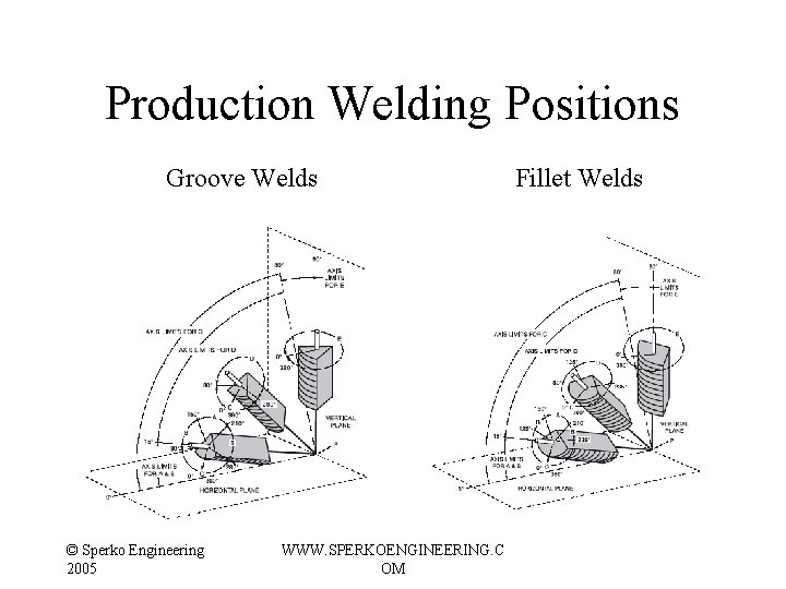
This presentation is copyrighted by Sperko Engineering • The primary purpose of this presentation is twofold: – Make sure that code users understand the difference between testing positions and production welding positions – Help users understand how to read the figures that define production welding positions shown on the next page. © Sperko Engineering 2005 WWW. SPERKOENGINEERING. C OM
Production Welding Positions Groove Welds © Sperko Engineering 2005 WWW. SPERKOENGINEERING. C OM Fillet Welds
Standard Test Positions 1 G, 3 G, 6 G, 2 F, 5 F, etc. are specially defined standard positions used for testing. They are properly referred to as Test Positions. Similar positions are found in ISO 6947 identified as PA, PC, PG, etc. © Sperko Engineering 2005 WWW. SPERKOENGINEERING. C OM
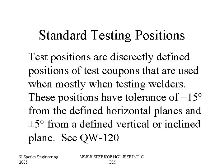
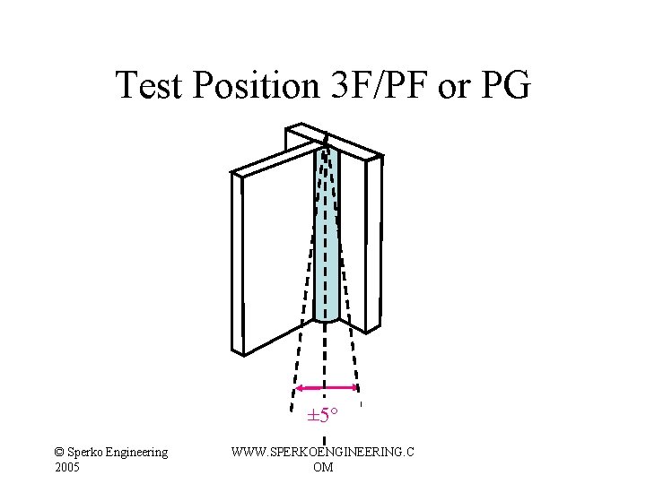
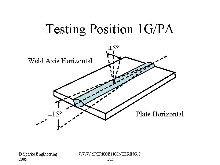
Standard Testing Positions Test positions are discreetly defined positions of test coupons that are used when mostly when testing welders. These positions have tolerance of ± 15° from the defined horizontal planes and ± 5° from a defined vertical or inclined plane. See QW-120 © Sperko Engineering 2005 WWW. SPERKOENGINEERING. C OM
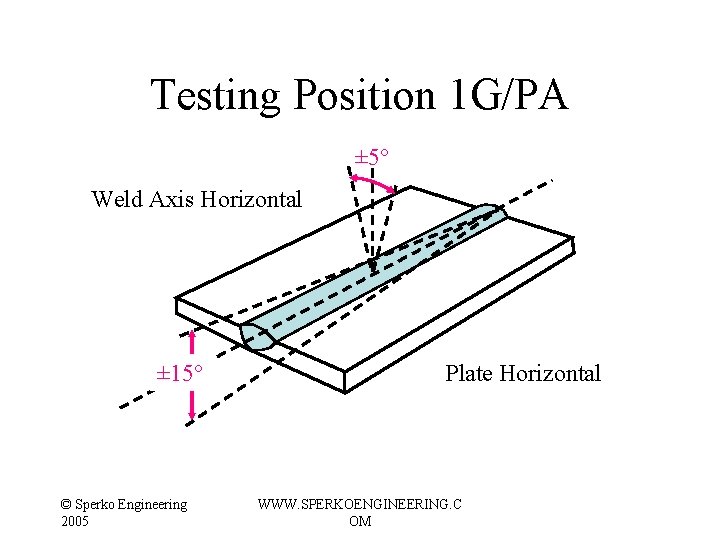
Testing Position 1 G/PA ± 5° Weld Axis Horizontal ± 15° © Sperko Engineering 2005 Plate Horizontal WWW. SPERKOENGINEERING. C OM
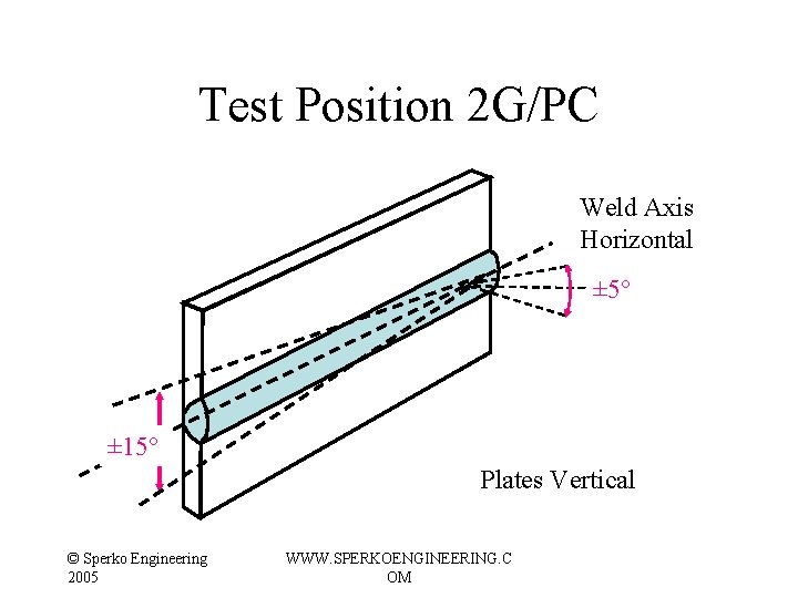
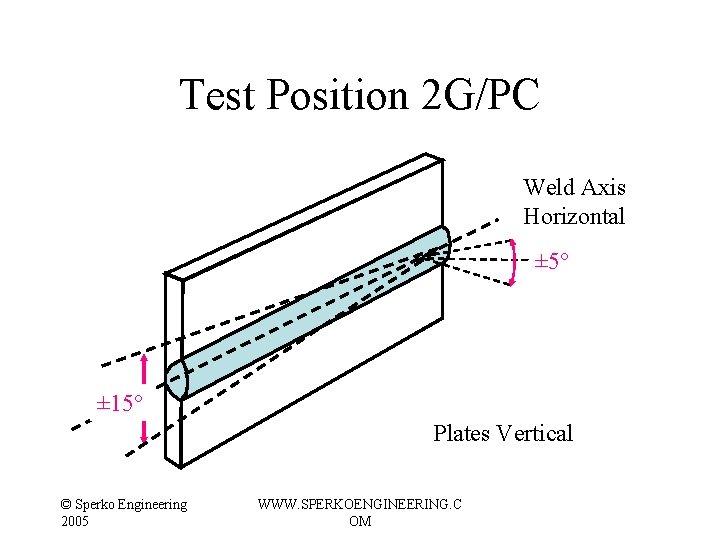
Test Position 2 G/PC Weld Axis Horizontal ± 5° ± 15° Plates Vertical © Sperko Engineering 2005 WWW. SPERKOENGINEERING. C OM
Test Position 3 F/PF or PG ± 5° © Sperko Engineering 2005 WWW. SPERKOENGINEERING. C OM
Test Position 6 G/HL 045 or JL 045 45°± 5° © Sperko Engineering 2005 WWW. SPERKOENGINEERING. C OM
Test Positions are Discreetly Defined • Because of tolerance limits on test positions, positions in between test positions are undefined! • That is, a weld that is inclined 22° uphill and rotated 36° about its axis has no “G” or “F” position. Such a position, however, may be encountered during production welding. • Production welding positions, therefore, need to be defined contiguously. © Sperko Engineering 2005 WWW. SPERKOENGINEERING. C OM
Test Positions Qualify Welders for Specific Welding Positions Test Positions Welding Positions Translations from test positions to welding positions are made in the construction codes. QW-461. 9 is typical. © Sperko Engineering 2005 WWW. SPERKOENGINEERING. C OM
Test Positions Welding Positions © Sperko Engineering 2005 WWW. SPERKOENGINEERING. C OM
Welding Positions Note to table: (1) Positions of welding as shown in QW-461. 1 and QW-461. 2 F = Flat H = Horizontal V = Vertical O = Overhead (2) Pipe 2 -7/8 in outside diameter and over. © Sperko Engineering 2005 WWW. SPERKOENGINEERING. C OM
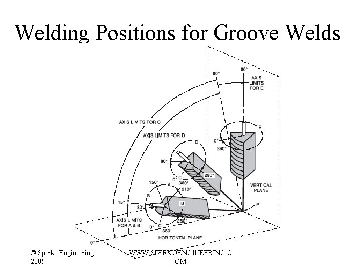
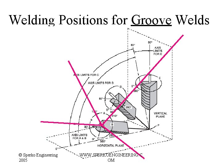
Welding positions for groove welds are defined by the following diagram. NOTE Welding Position Diagrams are contiguous. © Sperko Engineering 2005 WWW. SPERKOENGINEERING. C OM
Welding Positions for Groove Welds © Sperko Engineering 2005 WWW. SPERKOENGINEERING. C OM
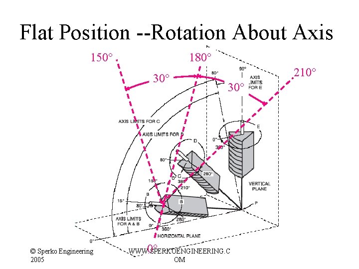
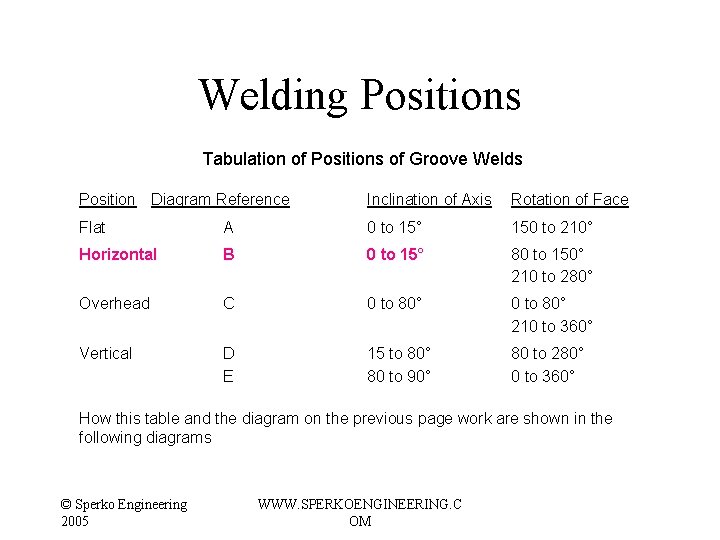
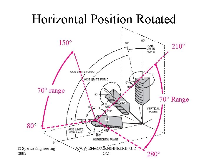
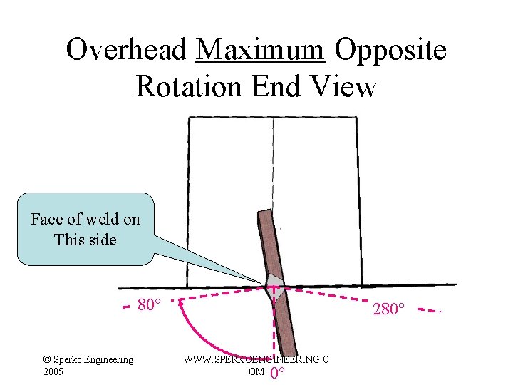
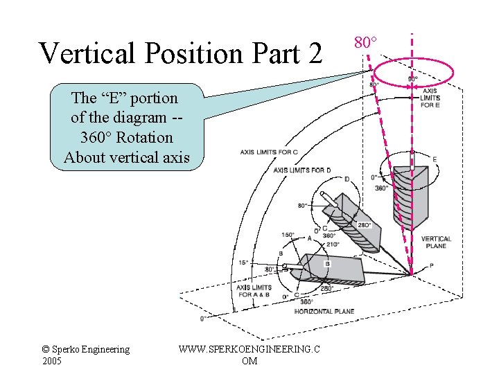
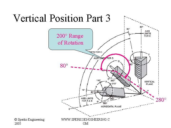
Tabulation showing transition points between welding positions Tabulation of Positions of Groove Welds Position Diagram Reference Inclination of Axis Rotation of Face Flat A 0 to 15° 150 to 210° Horizontal B 0 to 15° 80 to 150° 210 to 280° Overhead C 0 to 80° 210 to 360° Vertical D E 15 to 80° 80 to 90° 80 to 280° 0 to 360° How this table and the diagram on the previous page work are shown in the following diagrams © Sperko Engineering 2005 WWW. SPERKOENGINEERING. C OM
Let’s start with the Flat Position © Sperko Engineering 2005 WWW. SPERKOENGINEERING. C OM
Welding Positions Tabulation of Positions of Groove Welds Position Diagram Reference Inclination of Axis Rotation of Face Flat 0 to 15° 150 to 210° A Horizontal B 0 to 15° 80 to 150° 210 to 280° Overhead C 0 to 80° 210 to 360° Vertical D E 15 to 80° 80 to 90° 80 to 280° 0 to 360° How this table and the diagram on the previous page work are shown in the following diagrams © Sperko Engineering 2005 WWW. SPERKOENGINEERING. C OM
Flat Positions Axis Inclination 15° © Sperko Engineering 2005 WWW. SPERKOENGINEERING. C OM
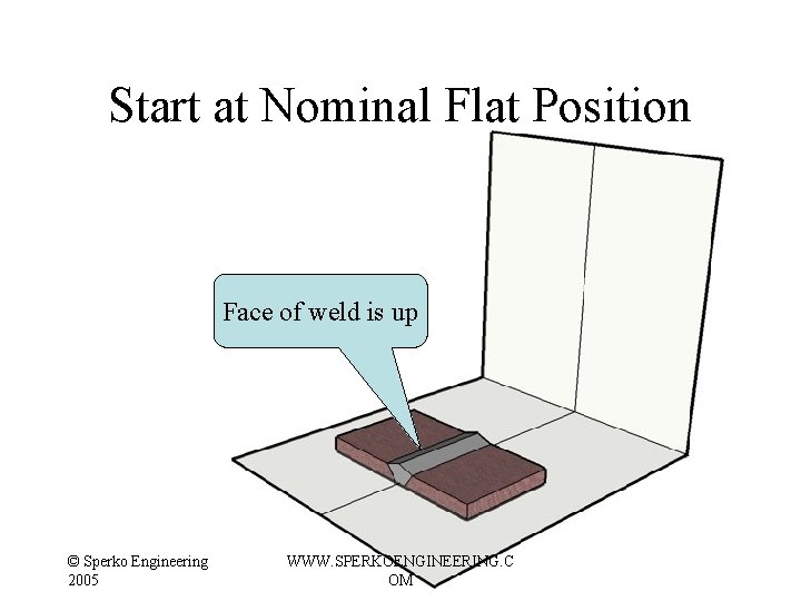
Start at Nominal Flat Position Face of weld is up © Sperko Engineering 2005 WWW. SPERKOENGINEERING. C OM
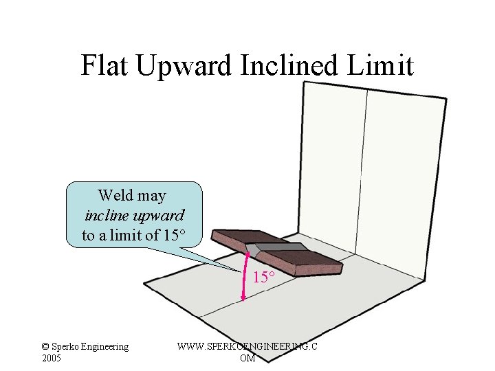
Flat Upward Inclined Limit Weld may incline upward to a limit of 15° © Sperko Engineering 2005 WWW. SPERKOENGINEERING. C OM
Flat Upward Inclined Limit But the welder could be traveling down the incline. . . 15° © Sperko Engineering 2005 WWW. SPERKOENGINEERING. C OM
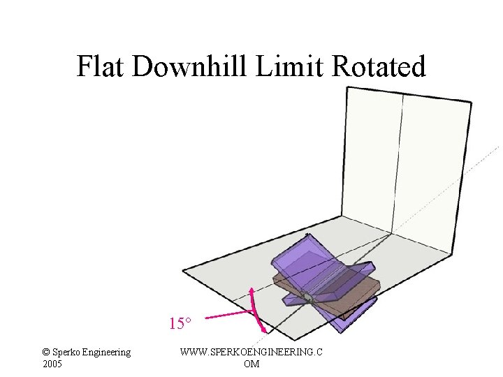
Flat Downward Limit Is Implied © Sperko Engineering 2005 15°WWW. SPERKOENGINEERING. C OM
Welding Positions Tabulation of Positions of Groove Welds Position Diagram Reference Inclination of Axis Rotation of Face Flat A 0 to 15° 150 to 210° Horizonta B 0 to 15° 80 to 150° 210 to 280° Overhead C 0 to 80° 210 to 360° Vertical D E 15 to 80° 80 to 90° 80 to 280° 0 to 360° How this table and the diagram on the previous page work are shown in the following diagrams © Sperko Engineering 2005 WWW. SPERKOENGINEERING. C OM
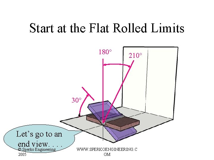
Flat Position --Rotation About Axis 180° 150° 30° © Sperko Engineering 2005 0° 210° 30° WWW. SPERKOENGINEERING. C OM
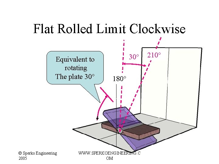
Flat Rolled Limit Clockwise 180° 30° © Sperko Engineering 2005 WWW. SPERKOENGINEERING. C OM 210°
Flat Rolled Limit Clockwise Equivalent to rotating The plate 30° © Sperko Engineering 2005 30° 180° WWW. SPERKOENGINEERING. C OM 210°
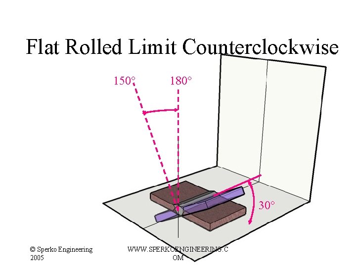
Flat Rolled Limit Counterclockwise 150° 180° 30° © Sperko Engineering 2005 WWW. SPERKOENGINEERING. C OM
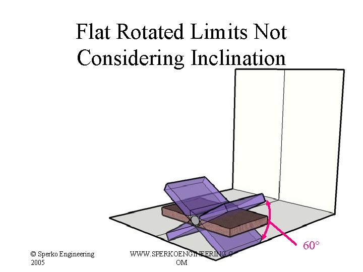
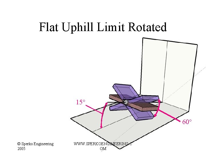
Flat Rotated Limits Not Considering Inclination © Sperko Engineering 2005 WWW. SPERKOENGINEERING. C OM 60°
Welding Positions Tabulation of Positions of Groove Welds Position Diagram Reference Inclination of Axis Rotation of Face Flat A 0 to 15° 150 to 210° Horizonta B 0 to 15° 80 to 150° 210 to 280° Overhead C 0 to 80° 210 to 360° Vertical D E 15 to 80° 80 to 90° 80 to 280° 0 to 360° How this table and the diagram on the previous page work are shown in the following diagrams © Sperko Engineering 2005 WWW. SPERKOENGINEERING. C OM
Flat Uphill Limit Rotated 15° 60° © Sperko Engineering 2005 WWW. SPERKOENGINEERING. C OM
Flat Downhill Limit Rotated 15° © Sperko Engineering 2005 WWW. SPERKOENGINEERING. C OM
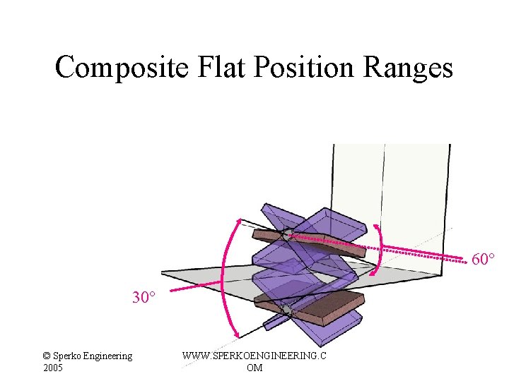
Composite Flat Position Ranges 60° 30° © Sperko Engineering 2005 WWW. SPERKOENGINEERING. C OM
Compare this range to 1 G/PA. . . © Sperko Engineering 2005 WWW. SPERKOENGINEERING. C OM
Testing Position 1 G/PA ± 5° Weld Axis Horizontal ± 15° © Sperko Engineering 2005 Plate Horizontal WWW. SPERKOENGINEERING. C OM
Flat ≠ 1 G !!!! © Sperko Engineering 2005 WWW. SPERKOENGINEERING. C OM
Welding Positions Tabulation of Positions of Groove Welds Position Diagram Reference Inclination of Axis Rotation of Face Flat A 0 to 15° 150 to 210° Horizontal B 0 to 15° 80 to 150° 210 to 280° Overhead C 0 to 80° 210 to 360° Vertical D E 15 to 80° 80 to 90° 80 to 280° 0 to 360° How this table and the diagram on the previous page work are shown in the following diagrams © Sperko Engineering 2005 WWW. SPERKOENGINEERING. C OM
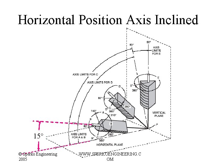
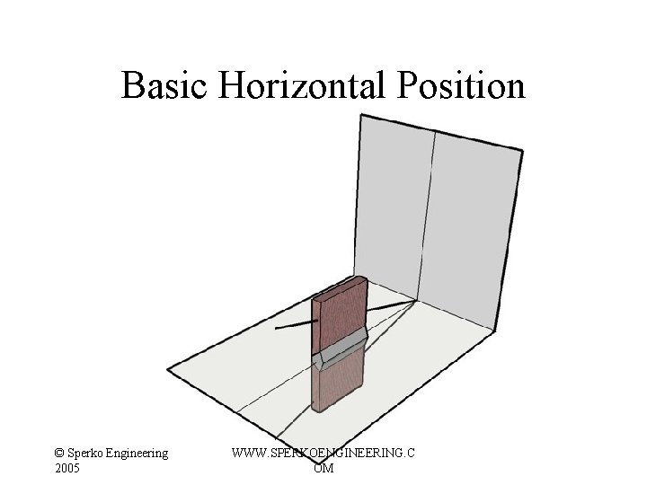
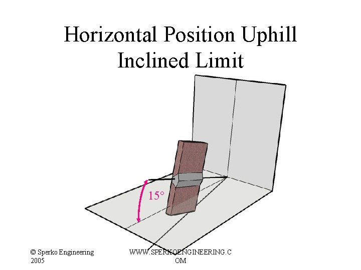
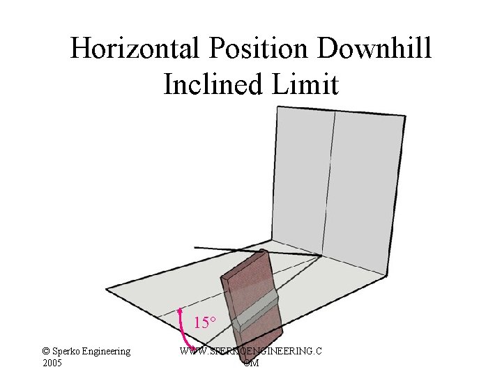
Horizontal Position Axis Inclined 15° © Sperko Engineering 2005 WWW. SPERKOENGINEERING. C OM
Basic Horizontal Position © Sperko Engineering 2005 WWW. SPERKOENGINEERING. C OM
Horizontal Position Uphill Inclined Limit 15° © Sperko Engineering 2005 WWW. SPERKOENGINEERING. C OM
Horizontal Position Downhill Inclined Limit 15° © Sperko Engineering 2005 WWW. SPERKOENGINEERING. C OM
Welding Positions Tabulation of Positions of Groove Welds Position Diagram Reference Inclination of Axis Rotation of Face Flat A 0 to 15° 150 to 210° Horizontal B 0 to 15° 80 to 150° 210 to 280° Overhead C 0 to 80° 210 to 360° Vertical D E 15 to 80° 80 to 90° 80 to 280° 0 to 360° How this table and the diagram on the previous page work are shown in the following diagrams © Sperko Engineering 2005 WWW. SPERKOENGINEERING. C OM
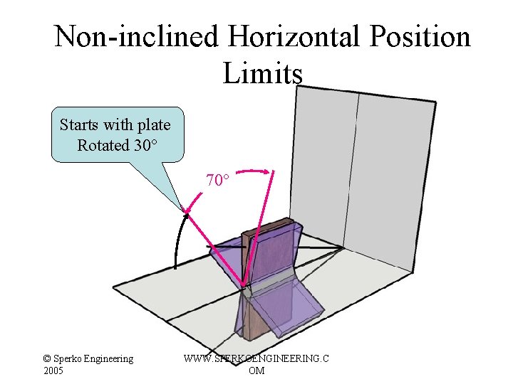
Horizontal Position Rotated 150° 210° 70° range 70° Range 80° © Sperko Engineering 2005 WWW. SPERKOENGINEERING. C OM 280°
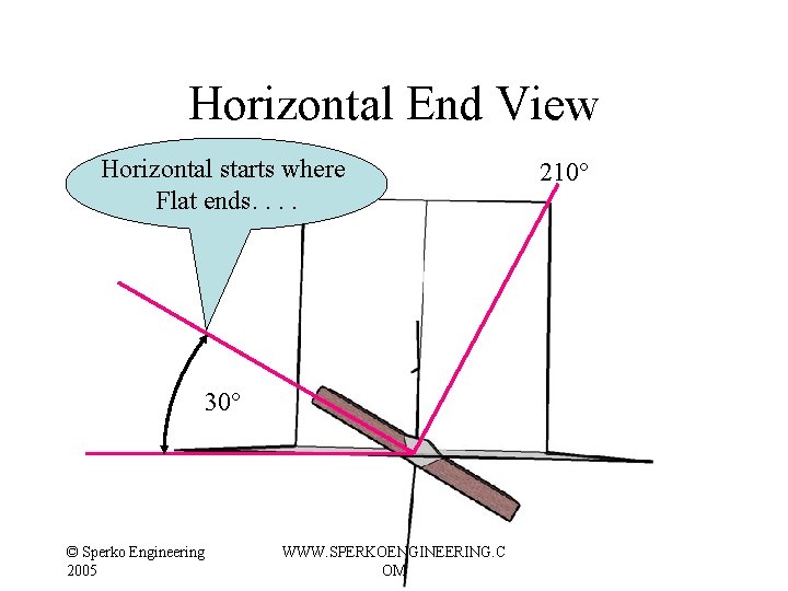
Start at the Flat Rolled Limits 180° 210° 30° Let’s go to an end view. . © Sperko Engineering 2005 WWW. SPERKOENGINEERING. C OM
Horizontal End View Horizontal starts where Flat ends. . 30° © Sperko Engineering 2005 WWW. SPERKOENGINEERING. C OM 210°
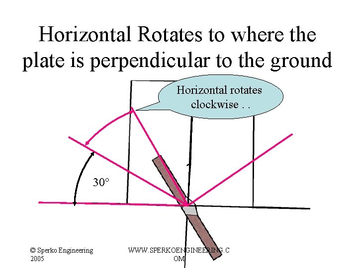
Horizontal Rotates to where the plate is perpendicular to the ground Horizontal rotates clockwise. . 30° © Sperko Engineering 2005 WWW. SPERKOENGINEERING. C OM
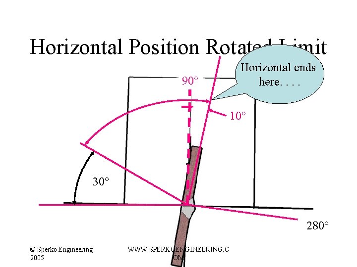
Horizontal Position Rotated Limit 90° Horizontal ends here. . 10° 30° 280° © Sperko Engineering 2005 WWW. SPERKOENGINEERING. C OM
Non-inclined Horizontal Position Limits Starts with plate Rotated 30° 70° © Sperko Engineering 2005 WWW. SPERKOENGINEERING. C OM
Non-inclined Horizontal Position Limits Finishes with plate Rotated 10° beyond perpendicular 70° © Sperko Engineering 2005 WWW. SPERKOENGINEERING. C OM
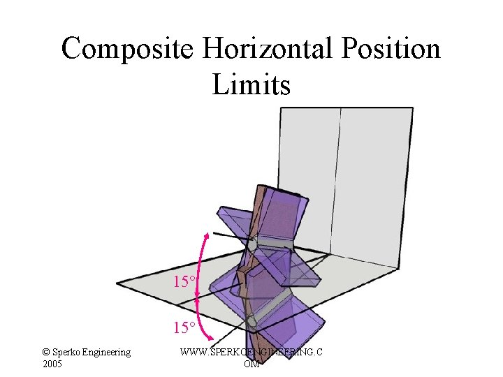
Composite Horizontal Position Limits 15° © Sperko Engineering 2005 WWW. SPERKOENGINEERING. C OM
Compare Horizontal to 2 G/PC © Sperko Engineering 2005 WWW. SPERKOENGINEERING. C OM
Test Position 2 G/PC Weld Axis Horizontal ± 5° ± 15° Plates Vertical © Sperko Engineering 2005 WWW. SPERKOENGINEERING. C OM
Horizontal ≠ 2 G/PC !!!! © Sperko Engineering 2005 WWW. SPERKOENGINEERING. C OM
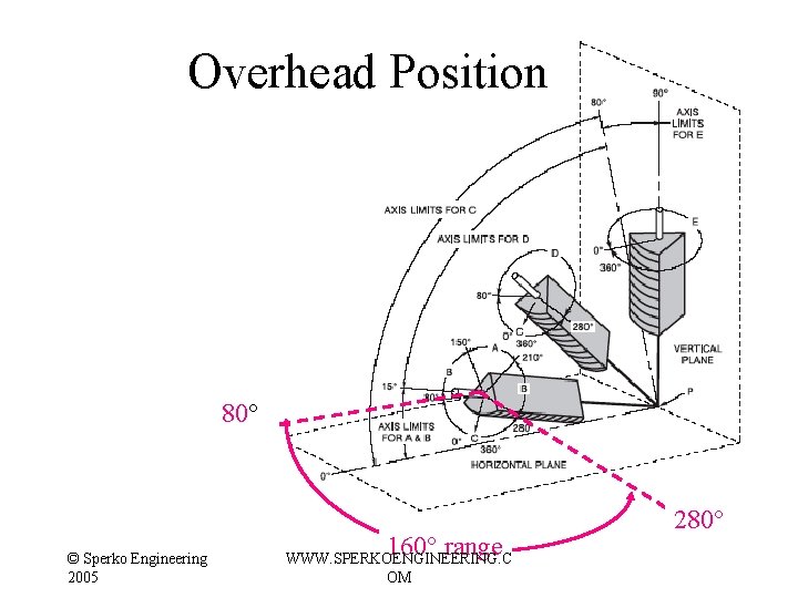
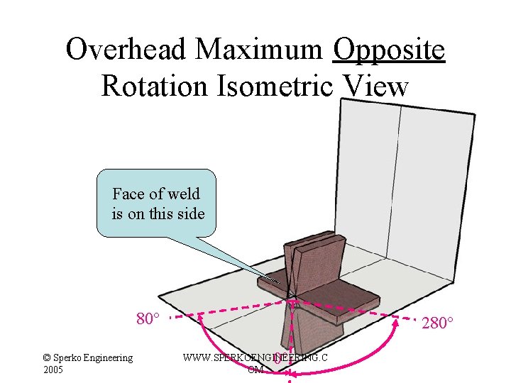
Overhead Position 80° © Sperko Engineering 2005 160° range WWW. SPERKOENGINEERING. C OM 280°
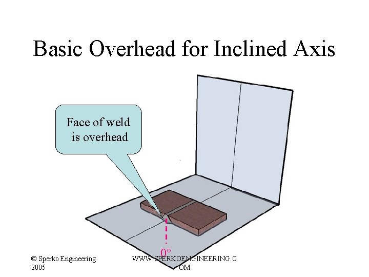
Basic Overhead Face of weld is overhead!!! 0° © Sperko Engineering 2005 WWW. SPERKOENGINEERING. C OM
Basic Overhead End View Face of weld overhead © Sperkois Engineering 2005 0° WWW. SPERKOENGINEERING. C OM
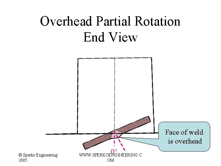
Overhead Partial Rotation End View Face of weld is overhead © Sperko Engineering 2005 0° WWW. SPERKOENGINEERING. C OM
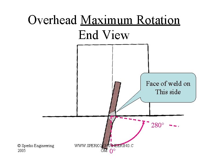
Overhead Maximum Rotation End View Face of weld on This side 280° © Sperko Engineering 2005 WWW. SPERKOENGINEERING. C OM 0°
Overhead Maximum Opposite Rotation End View Face of weld on This side 80° © Sperko Engineering 2005 280° WWW. SPERKOENGINEERING. C OM 0°
Same Rotation in Isometric View © Sperko Engineering 2005 WWW. SPERKOENGINEERING. C OM
Basic Overhead Face of weld is overhead © Sperko Engineering 2005 0° WWW. SPERKOENGINEERING. C OM
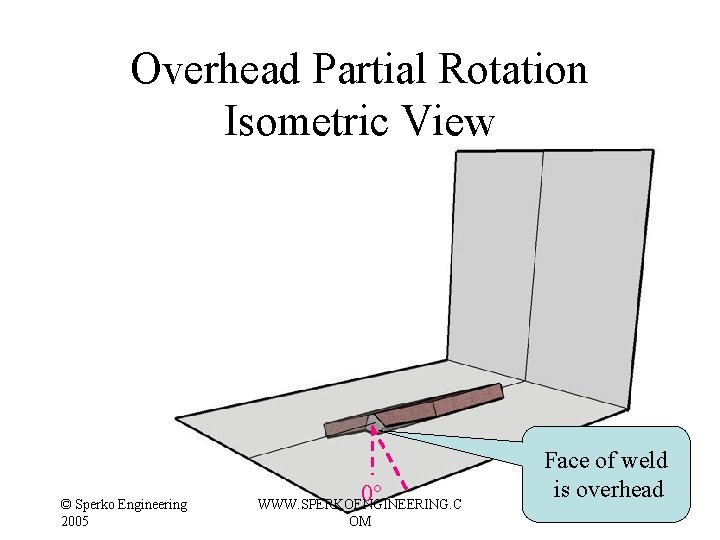
Overhead Partial Rotation Isometric View © Sperko Engineering 2005 0° WWW. SPERKOENGINEERING. C OM Face of weld is overhead
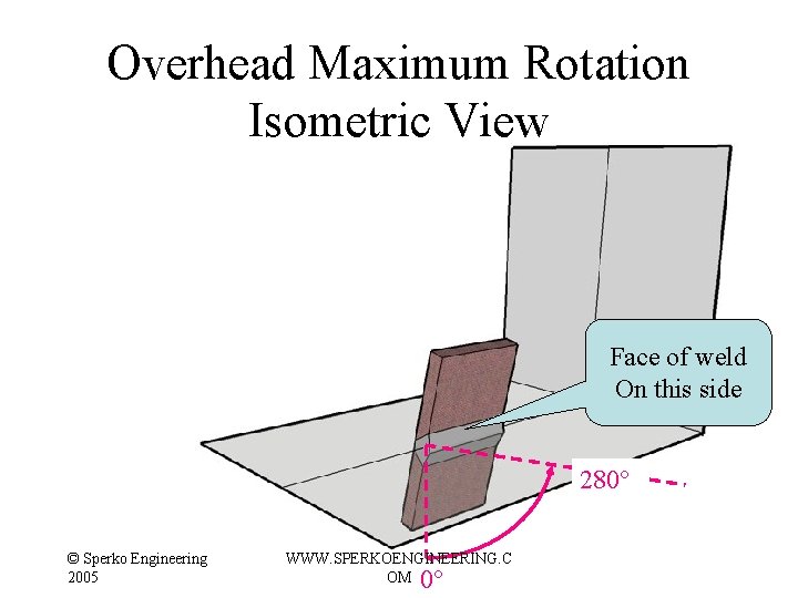
Overhead Maximum Rotation Isometric View Face of weld On this side 280° © Sperko Engineering 2005 WWW. SPERKOENGINEERING. C OM 0°
Overhead Maximum Opposite Rotation Isometric View Face of weld is on this side 80° © Sperko Engineering 2005 280° 0° WWW. SPERKOENGINEERING. C OM
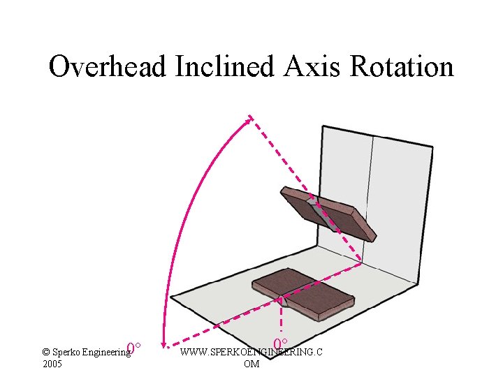
Overhead Position Axis Inclination 80° range 80° © Sperko Engineering 2005 160° range WWW. SPERKOENGINEERING. C OM 280°
Basic Overhead for Inclined Axis Face of weld is overhead © Sperko Engineering 2005 0° WWW. SPERKOENGINEERING. C OM
Overhead Inclined Axis Rotation 0° © Sperko Engineering 2005 0° WWW. SPERKOENGINEERING. C OM
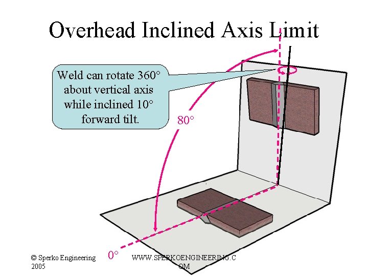
Overhead Inclined Axis Limit 80° 0° © Sperko Engineering 2005 WWW. SPERKOENGINEERING. C OM
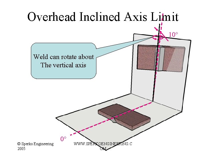
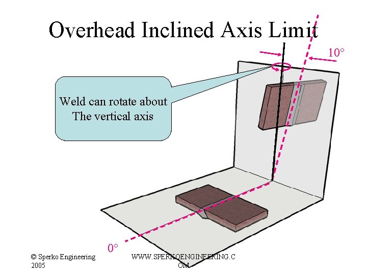
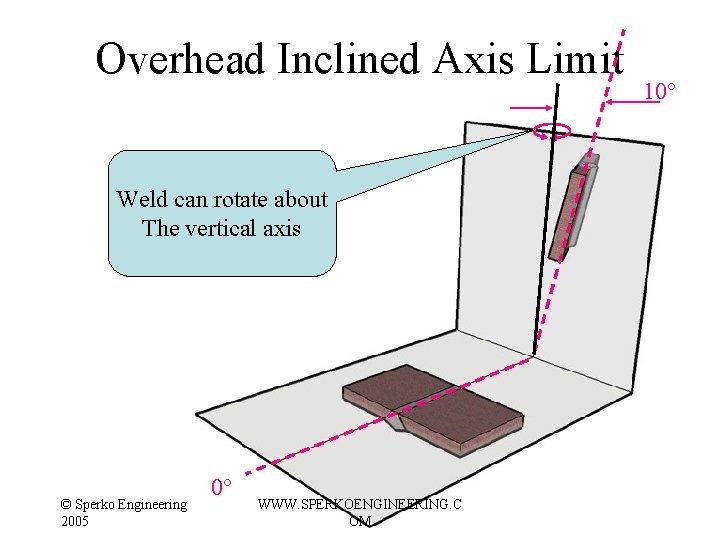
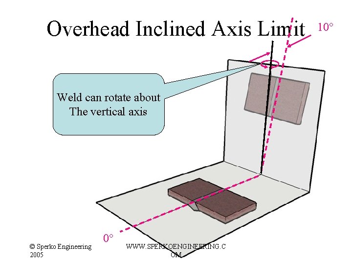
Overhead Inclined Axis Limit Weld can rotate 360° about vertical axis while inclined 10° forward tilt. © Sperko Engineering 2005 0° 80° WWW. SPERKOENGINEERING. C OM
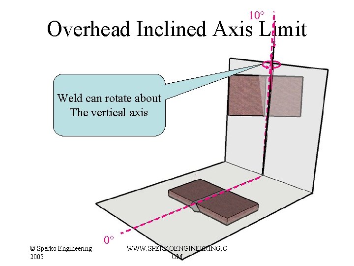
Overhead Inclined Axis Limit 10° Weld can rotate about The vertical axis © Sperko Engineering 2005 0° WWW. SPERKOENGINEERING. C OM
Overhead Inclined Axis Limit 10° Weld can rotate about The vertical axis © Sperko Engineering 2005 0° WWW. SPERKOENGINEERING. C OM
Overhead Inclined Axis Limit Weld can rotate about The vertical axis © Sperko Engineering 2005 0° WWW. SPERKOENGINEERING. C OM 10°
Overhead Inclined Axis Limit Weld can rotate about The vertical axis © Sperko Engineering 2005 0° WWW. SPERKOENGINEERING. C OM 10°
10° Overhead Inclined Axis Limit Weld can rotate about The vertical axis © Sperko Engineering 2005 0° WWW. SPERKOENGINEERING. C OM
Overhead Inclined Axis Limit 10° Weld can rotate about The vertical axis © Sperko Engineering 2005 0° WWW. SPERKOENGINEERING. C OM
Overhead Inclined Axis Limit 10° Weld ends up back Where it started! © Sperko Engineering 2005 0° WWW. SPERKOENGINEERING. C OM
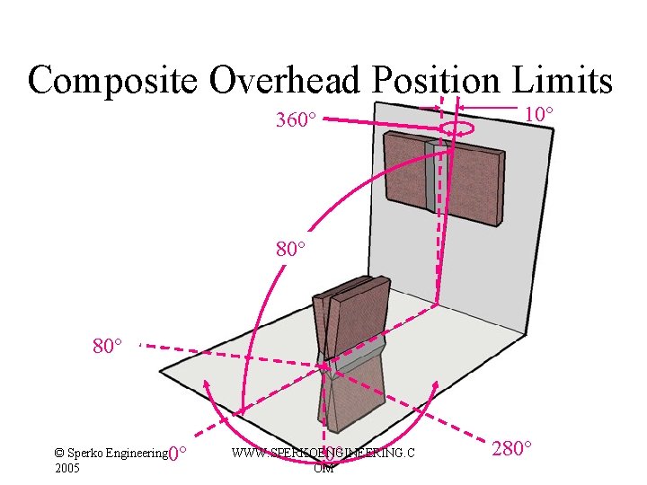
Composite Overhead Position Limits 10° 360° 80° © Sperko Engineering 2005 0° 0° WWW. SPERKOENGINEERING. C OM 280°
Overhead ≠ 4 G/PE !!!! © Sperko Engineering 2005 WWW. SPERKOENGINEERING. C OM
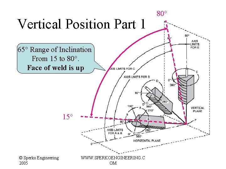
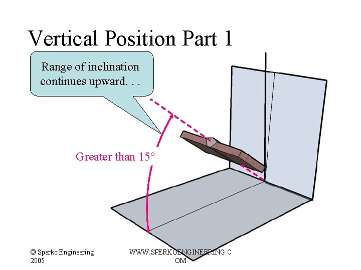
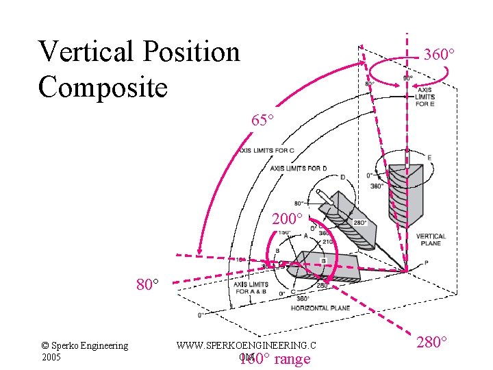
Vertical Position Part 1 65° Range of Inclination From 15 to 80°. Face of weld is up 15° © Sperko Engineering 2005 WWW. SPERKOENGINEERING. C OM 80°
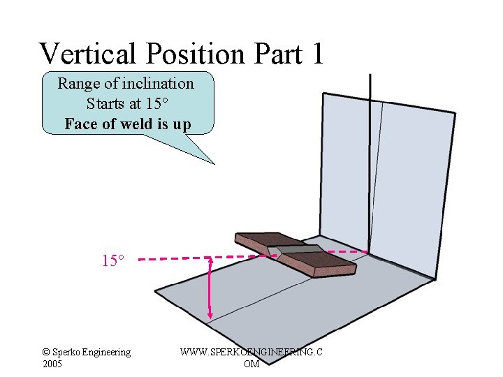
Vertical Position Part 1 Range of inclination Starts at 15° Face of weld is up 15° © Sperko Engineering 2005 WWW. SPERKOENGINEERING. C OM
Vertical Position Part 1 Range of inclination continues upward. . . Greater than 15° © Sperko Engineering 2005 WWW. SPERKOENGINEERING. C OM
Vertical Position Part 1 Until reaching 80° © Sperko Engineering 2005 WWW. SPERKOENGINEERING. C OM
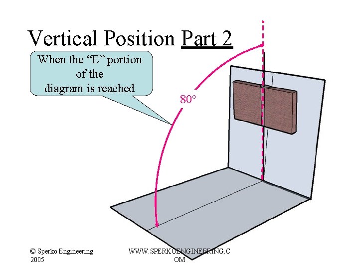
Vertical Position Part 2 When the “E” portion of the diagram is reached © Sperko Engineering 2005 80° WWW. SPERKOENGINEERING. C OM
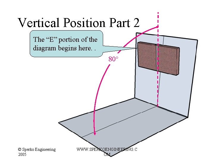
Vertical Position Part 2 The “E” portion of the diagram -360° Rotation About vertical axis © Sperko Engineering 2005 WWW. SPERKOENGINEERING. C OM 80°
Vertical Position Part 2 The “E” portion of the diagram begins here. . 80° © Sperko Engineering 2005 WWW. SPERKOENGINEERING. C OM
Vertical Position Part 2 Partial rotation about Vertical axis © Sperko Engineering 2005 WWW. SPERKOENGINEERING. C OM
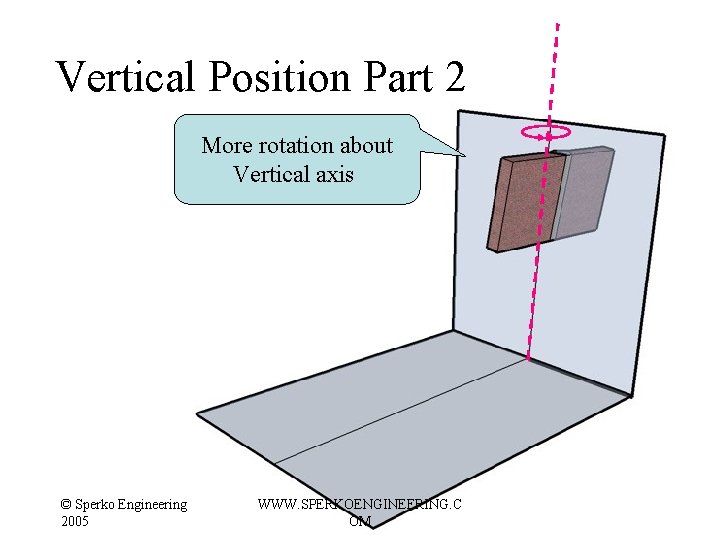
Vertical Position Part 2 More rotation about Vertical axis © Sperko Engineering 2005 WWW. SPERKOENGINEERING. C OM
Vertical Position Part 2 Even more rotation about Vertical axis © Sperko Engineering 2005 WWW. SPERKOENGINEERING. C OM
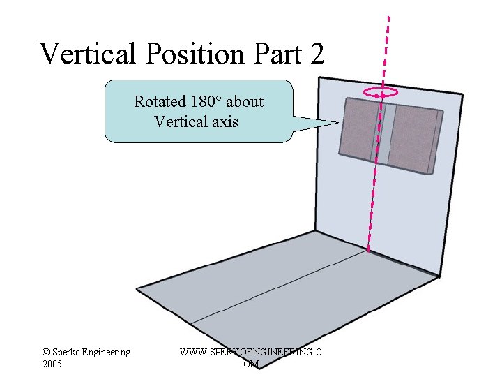
Vertical Position Part 2 Rotated 180° about Vertical axis © Sperko Engineering 2005 WWW. SPERKOENGINEERING. C OM
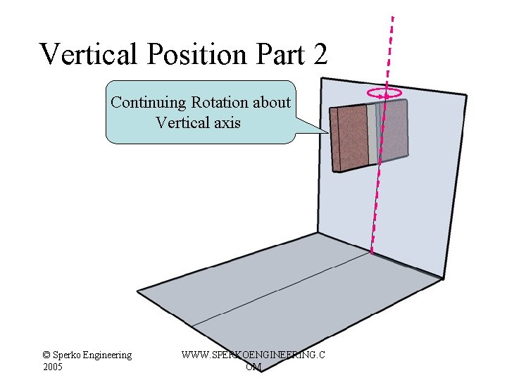
Vertical Position Part 2 Continuing Rotation about Vertical axis © Sperko Engineering 2005 WWW. SPERKOENGINEERING. C OM
Vertical Position Part 2 Continuing Rotation about Vertical axis © Sperko Engineering 2005 WWW. SPERKOENGINEERING. C OM
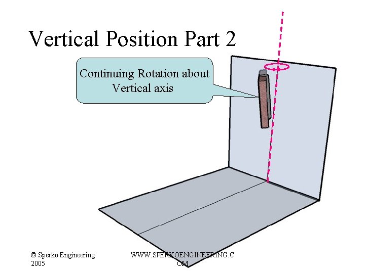
Vertical Position Part 2 Continuing Rotation about Vertical axis © Sperko Engineering 2005 WWW. SPERKOENGINEERING. C OM
Vertical Position Part 2 360° of Rotation about Vertical axis completed © Sperko Engineering 2005 WWW. SPERKOENGINEERING. C OM
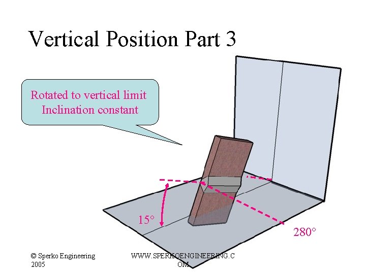
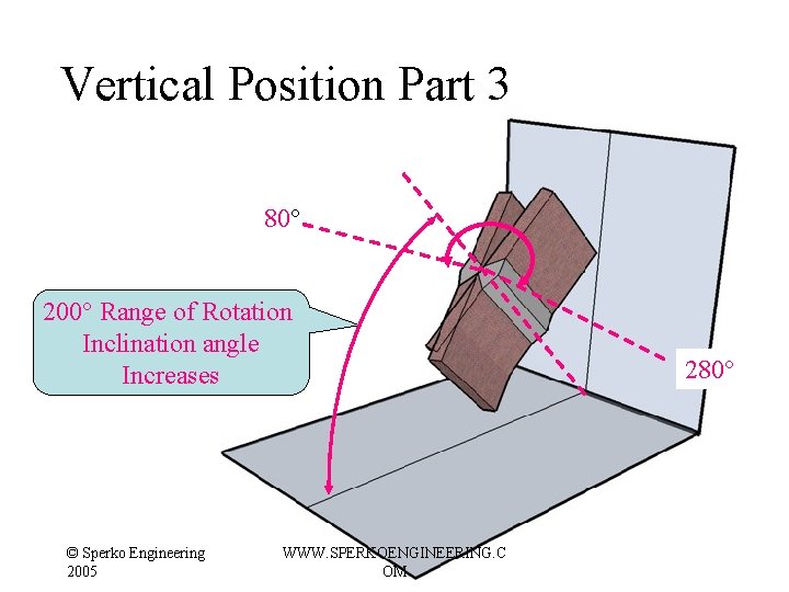
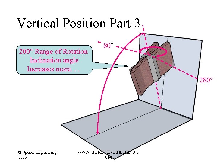
Vertical Position Part 3 200° Range of Rotation 80° 280° © Sperko Engineering 2005 WWW. SPERKOENGINEERING. C OM
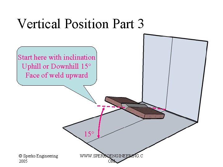
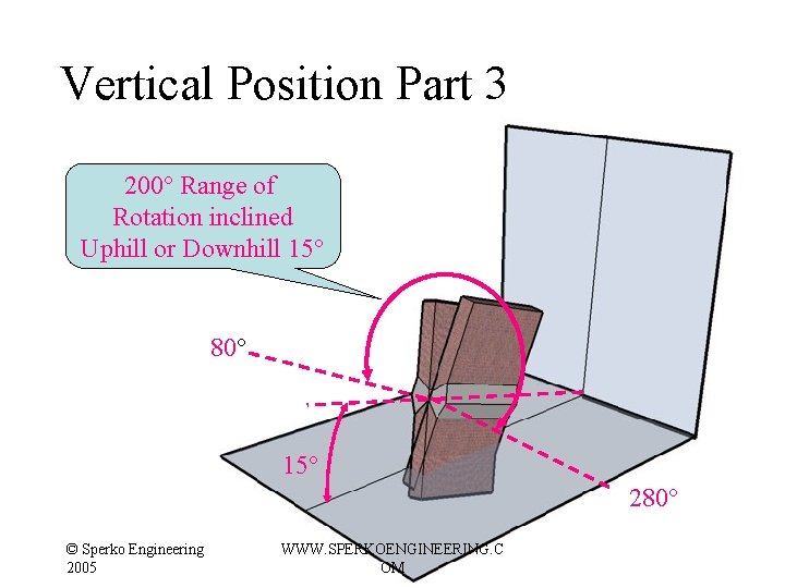
Vertical Position Part 3 Start here with inclination Uphill or Downhill 15° Face of weld upward 15° © Sperko Engineering 2005 WWW. SPERKOENGINEERING. C OM
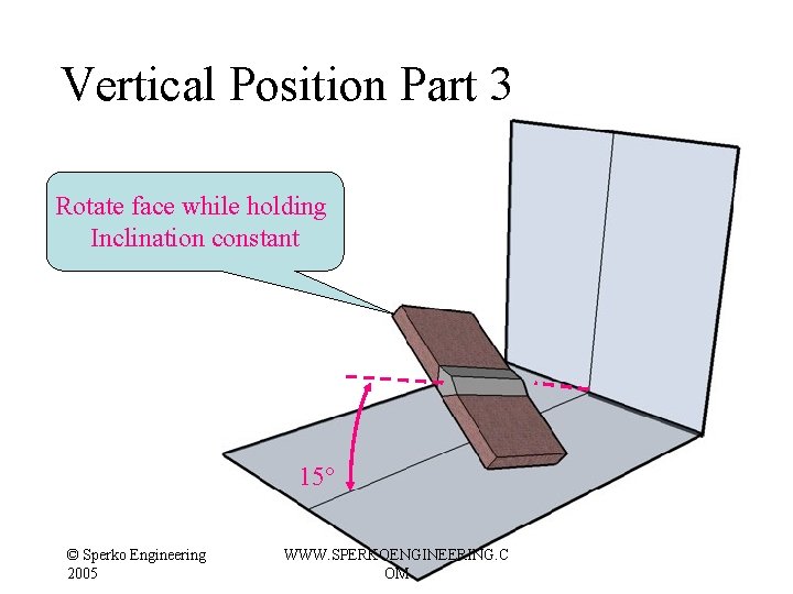
Vertical Position Part 3 Rotate face while holding Inclination constant 15° © Sperko Engineering 2005 WWW. SPERKOENGINEERING. C OM
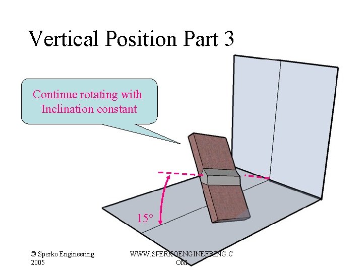
Vertical Position Part 3 Continue rotating with Inclination constant 15° © Sperko Engineering 2005 WWW. SPERKOENGINEERING. C OM
Vertical Position Part 3 Rotated to vertical limit Inclination constant 15° © Sperko Engineering 2005 WWW. SPERKOENGINEERING. C OM 280°
Vertical Position Part 3 Return to starting position Uphill or Downhill 15° Face of weld upward 15° © Sperko Engineering 2005 WWW. SPERKOENGINEERING. C OM
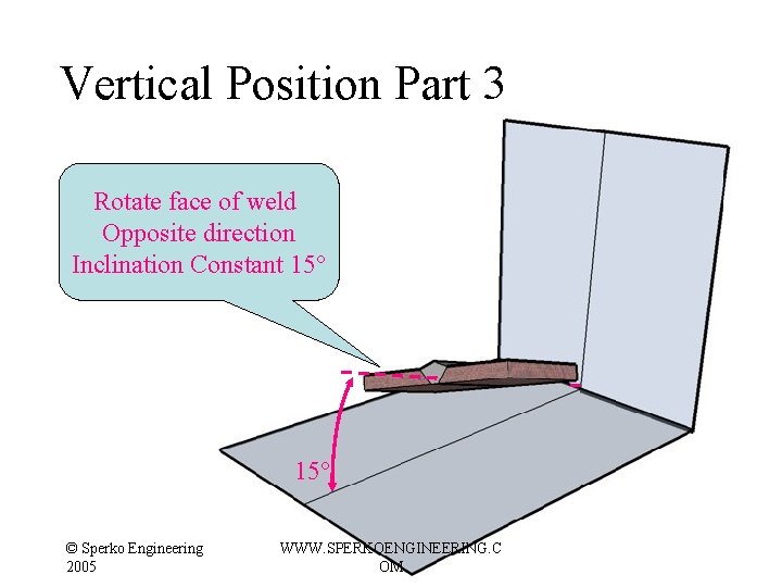
Vertical Position Part 3 Rotate face of weld Opposite direction Inclination Constant 15° © Sperko Engineering 2005 WWW. SPERKOENGINEERING. C OM
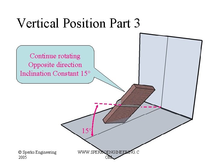
Vertical Position Part 3 Continue rotating Opposite direction Inclination Constant 15° © Sperko Engineering 2005 WWW. SPERKOENGINEERING. C OM
Vertical Position Part 3 Plate near vertical Inclination Constant 15° © Sperko Engineering 2005 WWW. SPERKOENGINEERING. C OM
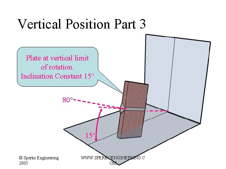
Vertical Position Part 3 Plate at vertical limit of rotation. Inclination Constant 15° 80° 15° © Sperko Engineering 2005 WWW. SPERKOENGINEERING. C OM
Vertical Position Part 3 200° Range of Rotation inclined Uphill or Downhill 15° 80° 15° 280° © Sperko Engineering 2005 WWW. SPERKOENGINEERING. C OM
Vertical Position Part 3 80° 200° Range of Rotation Inclination angle Increases © Sperko Engineering 2005 WWW. SPERKOENGINEERING. C OM 280°
Vertical Position Part 3 200° Range of Rotation Inclination angle Increases more. . . 80° 280° © Sperko Engineering 2005 WWW. SPERKOENGINEERING. C OM
Vertical Position Composite 360° 65° 200° 80° © Sperko Engineering 2005 WWW. SPERKOENGINEERING. C OM 160° range 280°
Welding Positions for Fillet Welds © Sperko Engineering 2005 WWW. SPERKOENGINEERING. C OM
Flat Fillet Weld © Sperko Engineering 2005 WWW. SPERKOENGINEERING. C OM
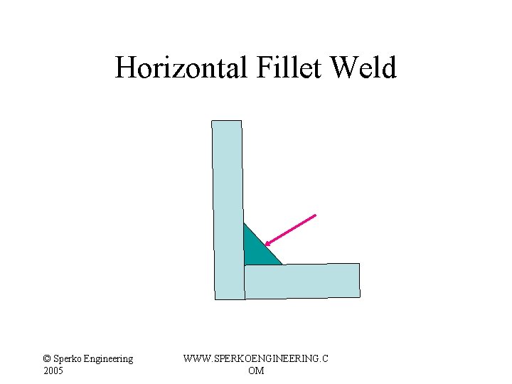
Horizontal Fillet Weld © Sperko Engineering 2005 WWW. SPERKOENGINEERING. C OM
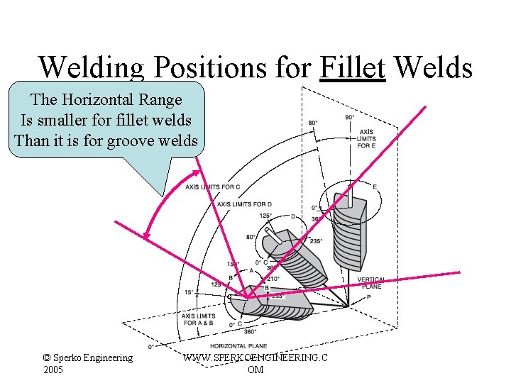
Welding Positions for Fillet Welds © Sperko Engineering 2005 WWW. SPERKOENGINEERING. C OM
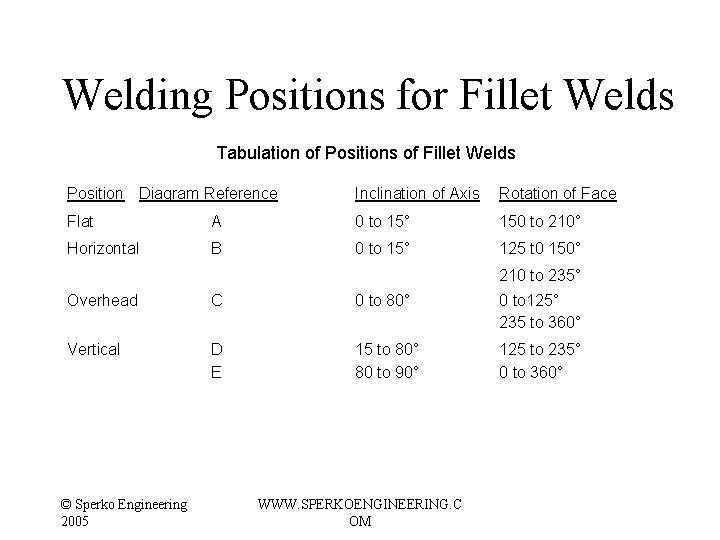
Welding Positions for Fillet Welds Tabulation of Positions of Fillet Welds Position Diagram Reference Inclination of Axis Rotation of Face Flat A 0 to 15° 150 to 210° Horizontal B 0 to 15° 125 t 0 150° 210 to 235° Overhead C 0 to 80° 0 to 125° 235 to 360° Vertical D E 15 to 80° 80 to 90° 125 to 235° 0 to 360° © Sperko Engineering 2005 WWW. SPERKOENGINEERING. C OM
Welding Positions for Fillet Welds The Horizontal Range Is smaller for fillet welds Than it is for groove welds © Sperko Engineering 2005 WWW. SPERKOENGINEERING. C OM
Welding Positions for Groove Welds © Sperko Engineering 2005 WWW. SPERKOENGINEERING. C OM
Questions? Feedback? Can you explain the diagrams to your friends? Send e-mail to: Sperko@asme. org © Sperko Engineering 2005 WWW. SPERKOENGINEERING. C OM