Technology Readiness Assessment TRA Introduction to the NAVAIR


- Slides: 52

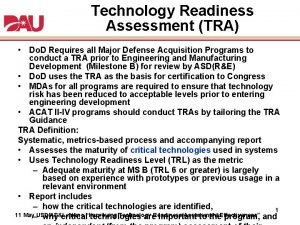
Technology Readiness Assessment (TRA) “Introduction to the NAVAIR Process” Presented to DAU Orion 21 3 April 2007 Edward J. Copeland NAVAIR TRA Chairman Avionics Department National Chief Engineer (AIR-4. 5) Director, Independent Technical Review Office (AIR-4. 0 TRA) Edward. Copeland@navy. mil Phone: (301) 342 -9154

AIR-4. 0 TRA ITRO & 4. 5 CHENG Team RDML S. Eastburg / Mr. J. Mc. Curdy AIR-4. 0 / 4. 0 A Mr. Larry E. Hollingsworth AIR-4. 5 Mr. Edward J. Copeland ONR ITRO Director, AIR-4. 0 TRA NAVAIR TRA Chairman AIR-4. 5 CHENG Mr. Joe Laska ITRO Deputy Director NAVAIR Fellows Mr. Lawson Glenn Engineering Rotation Project Engineer #1 Ms. Kimberly Cawood, AMPAC Admin Support Mr. John Walker, 4. 1. 4 Senior Software Engr Mr. Dale Hollen, MANTECH Mr. Don Spry, Eagle Systems Inc Engineering CSS Support Project Engineer #2 JHU APL Ms. Judy Miller, 7. 8. 1. 2 Business and Finance CAO National Experts Data Analyst Potential Growth

Brief Outline • • • General Background Critical Technology Element TRA POAM Considerations Roles & Responsibilities Requirements Evolution TRA Process – CTE Reconciliation – CTE TRL Assessment – Reporting of Results • Take Away

AIR-4. 0 Designation Letter “I hereby designate Mr. Edward J. Copeland, NAVAIRSYSCOM Fellow, as the AIR-4. 0 Research and Engineering TRA Chairman and principal TRA point-of contact for all NAVAIRSYSCOM programs. ”

HLR MMA AHE GQM-163 TRAs AESA VXX

ITRO TRA/TMA Activities As of Dec 2006 Known ACAT PGM TRAs w/ TBD Milestone Dates 13 (not included) Increasing Trend Consistent w/ AIR-1. 0 Database Dec 2006 Run-date ACAT PGM Visibility Uncertainty in Out-Years

Agenda • • • General Background Critical Technology Element TRA POAM Considerations Roles & Responsibilities Requirements Evolution TRA Process – CTE Reconciliation – CTE TRL Assessment – Reporting of Results • Take Away

Why the Drive for TRAs ? Non-Mature Technologies (Part of Problem): ~ Avg 32% Additional Cost Growth ~ Avg 6 Mo Additional Schedule Delay Programs need to be more successful in achieving cost and schedule targets ~ TRA Process helps programs meet goals

TRA Background • NASA first established the use of Technology Readiness Levels (TRLs) in the late 1980’s – Applied to Program Reviews – Evolved from 7 levels to today’s 9 levels • Do. D adopted the use of TRLs for new Major programs in 2001 per DUSD(S&T/DDR&E) Memorandum – Response to GAO recommendation to assess technology maturity prior to technology transition – Established 9 levels modeled from NASA index – Definitions are similar but different from NASA • Do. D initial TRA guidance in 2003 per Do. D TRA Deskbook • Today Do. D has referenced the importance of technology maturity in the Do. D 5000 series acquisition documentation, Do. D Defense Acquisition Guidebook, and the current 2005 Do. D TRA Deskbook – Established both System/hardware TRLs and Software TRLs – http: //www. defenselink. mil/ddre/doc/tra_deskbook_2005. pdf

TRA, “What is it? ” • Systematic metrics based process used to assess the maturity of Critical Technology Elements (CTEs) – Utilizes Technology Readiness Level’s (TRLs) as a metric to assess estimated CTE maturity – The TRA helps identify areas for program risk management, but is Not a Risk Assessment – TRA assumes a threshold compliant design and assesses the technology maturity of the elements that make up the design foundation of which the design is dependent – TRA addresses Hardware and Software – Assessment Event “Draws a Line in the Sand” for determining technology maturity • No credit for future accomplishments when assigning TRLs

Agenda • • • General Background Critical Technology Element TRA POAM Considerations Roles & Responsibilities Requirements Evolution TRA Process – CTE Reconciliation – CTE TRL Assessment – Reporting of Results • Take Away

Critical Technology Elements (CTEs) • The term Critical Technology has become a universal phrase with many different connotations and definitions – Mission Critical Technology List – Critical Program Information – Important technologies for Mission Success • In the context of technology readiness based on technology maturity the Critical Technology translation is unique – To avoid confusion and to uniquely associate the TRA application apart from the others the Critical Technology Element (CTE) terminology was born – CTE terminology is uniquely associated to the TRA process

Critical Technology Elements (CTEs) • A CTE equates to a “New” or “Novel” technology – Merriam – Webster Definition: • New ~ “new and not resembling something formally known or used” • Novel ~ “applies to what is not only new but strange or unprecedented” • The “E” in CTE originated from the association of Technology Readiness Levels (TRLs) – TRLs are based on Elemental levels of integrated demonstrations • Component subsystem/system for increasing Elemental levels of demonstrated integration • Relevant operational for increasing elemental demonstrations in mission relatable physical/logical environments (static to dynamic) Critical Technology Elements: If a system being acquired depends on specific technologies to meet system operational requirements in development, production, and operation and if the technology or its application is either “new or novel”.

Basic Criteria for Determining CTEs Given(s): • All Technologies are directly traceable to an operational threshold requirement unless included by PM as Cost Reduction Initiative (CRI) or approved performance enhancement – CTEs identified will be directly traceable to both an operational requirement and/or accepted PM configuration change – Not all operational threshold requirements are Key Performance Parameters (KPPs) • KPPs represent only a small subset of overall requirements set • Typically 100’s of threshold requirements vice ~ 10 or less KPP requirements CTEs may or may not be traceable to KPP requirements (Requirements traceability maintained by PM)

Basic Criteria for Determining CTEs • If a Program has “n” CTEs – May or May Not be KPP related – CTEs may be enabling technologies, performance margin, or cost reduction initiatives that can be traded if necessary – CTEs may have potential non-CTE fall-back alternatives – CTEs could be low risk to the program A single TRL characterization of a Program is misleading

Basic Criteria for Determining CTEs Additional Given(s): • Technology is considered part of the product configuration baseline – Part of “Program of Record” being assessed • Directly impacts performance, affordability, manufacturing, and evolutionary spirals – Milestone B ~ Conceptual/Proposed design to meet threshold performance – Milestone C ~ Production representative configuration

Basic Criteria for Determining CTEs • If “Yes” then CTE: Is the technology New or Novel? – Note: A new product does not dictate a new technology • If “Yes” to the following additional questions then further discussion required to determine significance before CTE determination – Has the technology been modified? – Has the technology been repackaged such that a new and more stressful relevant environment is realized? – Is the technology expected to operate in an environment and/or achieve a performance expectation beyond it’s original design intention or demonstrated capability? Is the physics or engineering understood and scaleable from similar proven technology product families?

Agenda • • • General Background Critical Technology Element TRA POAM Considerations Roles & Responsibilities Requirements Evolution TRA Process – CTE Reconciliation – CTE TRL Assessment – Reporting of Results • Take Away

Chair § TRL Scoring Phase § TRA Reporting Phase - Read Ahead - Brief/Report Development > Data Analysis > Panel Review > Report Preparation - TRA Event > Maturation Plan Development § Coordination Mtgs - CNR / DASN Chair Brief-Out § TRA Plan - DUSD(S&T)/DDR&E Review Chair, CNR/TRAC, DASN(S&T), § TRA Kickoff Meeting § CTE Reconciliation Phase - CTE WBS Development > Informal Steering Reviews > Pre-Reconciliation Reviews - CTE Reconciliation Review § Coordination Mtgs (OSD, ONR) Chair, CNR/TRAC, DASN(S&T), DUSD(S&T)/DDR&E ACAT TRA POAM Variation MDA: DUSD(AT&L) ACAT 1 D & IAM ACAT 1 C, II MDA: ASN(RDA) ACAT III, IVM MDA: PEO 5 -6 Months 2 months 1 -2 months 7 -10 Months 3 -4 months 2 -3 months Staffing Chain To MDA 2 -3 months 9 -12 Months 4 -5 months 2 -3 months 3 -4 months Note: ACAT, Milestone, Calendar period & Acquisition Complexities will vary resources, time, and cost required

Milestone B TRA POAM Complexities Include • Ability to Estimate w/ Confidence Conceptual Allocated Baseline Designs as Probable Proposals to RFP • Acquisition Strategy Impacts – – – Sole Source or Open Competition ? Number of Offerers ? Number of Potential Choices to Address Requirements ? CONOPS Available ? Operational Requirements Stability ? • Systems Requirements Review (SRR) Timing • NROC, JROC, CDD, etc. – Joint Program ~ MOA Necessary – Multi-Service PEO Signatures – Single S&T Executive TRA – Single Service Secretary Endorsement – Spiral/Incremental Development ? – Contractor Pre-Development Phase or Not ? Impacts Influence Time & Effort Required to Complete CTE WBS and Reconcile CTEs

Sample ACAT-1 D Program TRA POAM FY 07 FY 06 Feb 06 Mar 06 Apr 06 May 06 Jun 06 Jul 06 Aug 06 Sep 06 Oct 06 Nov 06 Dec 06 Program Milestones Jan 07 Feb 07 Mar 07 MS Doc Tgt Apr 07 May 07 MS C Wkly Chair / APMSE Status Meetings: MS-C Technology Readiness Assessment (TRA) WBS-linked CTEs ITA Window, if Req’d RA TRA Chair & APMSE WBS Review (Informal) CTE Pre- Reconciliation Working Offsite (MANTECH, Lex Prk) Airspeed 6 -Sigma CTE Official Reconciliation Offsite Window Of Opportunity ASN/OSD TRA Report Review TRA Event Read-Ahead Dev. TRA Kick-Off Meeting w/ IPT Informal RA TRA Chair Rvw TRA Plan Signed Chair Brief OSD TRA Plan Final To Panel TRA Event TRA CNR/DASN Joint Brief Endorsement To Letter CNR/DASN To ASN(RDA) DDR&E Endorsement Letter to OUSD TRA Gen Refresher/Report Training (IPT / Panel) Chair Brief OSD TRA Results Follow-Up Brief to OSD (if Required)

Agenda • • • General Background Critical Technology Element TRA POAM Considerations Roles & Responsibilities Requirements Evolution TRA Process – CTE Reconciliation – CTE TRL Assessment – Reporting of Results • Take Away

Roles & Responsibilities (1) • Chairman – Establishes agreed-to schedule for TRA w/ PM & TRAC – Facilitates and clarifies the proper identification of Critical Technologies • Utilizes NAVAIR Fellows / Grey Beards in Vetting Process w/ PM IPT leads – – Develops TRA plan and report Establishes and Obtains Concurrence w/ ONR TRAC on TRA Panel Coordinates and facilitates the execution of the TRA Implements agreed-to process between NAVAIR and ONR • Utilizes NAVAIRINST 4355. 19 C SETR TRA Handbook, Module, & Checklist – Embraces DOD TRA Deskbook – Maintains close coordination w/ TRAC on TRA plan and report prior to submission to CNR – Clarifies report content w/ CNR directly if questions

Roles & Responsibilities (2) • ONR TRA Coordinator (TRAC) – CNR agent to maintain independent certification of TRA process – Collaborates with Chairman for ensuring adequate TRA plan, membership, and report submittal – Participates as equal member on TRA Panel • Program Manager (PM) – – – Provides insight into platform CONOPS and operational requirements Provides trace of operational requirements to identified critical technologies Defines system concept(s) and associated architectures Identifies Critical Technology Elements (CTEs) to platform WBS Responsible for CTE Maturation Plans Provides for access to TRA materials given sensitive and/or proprietary environment (i. e. , non-disclosure, classified) – Prime Contractor involvement encouraged • Contractual language to support TRA tasks (samples available) • CDRLs – Funds TRA Efforts

Agenda • • • General Background Critical Technology Element TRA POAM Considerations Roles & Responsibilities Requirements Evolution TRA Process – CTE Reconciliation – CTE TRL Assessment – Reporting of Results • Information Dissemination

TRA Requirements Flow DODD 5000. 1 12 May 2003 A central theme of the acquisition process is that the technology employed should be “mature” before system development begins. Defense Acquisition Guidebook Nov 2004 Introduces TRA process highlights and the use TRLs DODI 5000. 2 12 May 2003 Establishes the requirement for all acquisition programs to conduct Technology Readiness Assessments (TRAs) OUSD(S&T) TRA Desk Book Mar 2005 Provides TRA process guidelines and includes HDW and SOFT TRLs Listed in Encl 3: Regulatory Info & MS Requirements SECNAVINST 5000. 2 C AF 19 Nov 2004 ARMY Establishes the requirement for Navy acquisition programs (ACAT I, IA, III, IV) to conduct Technology Readiness Assessments (TRAs) Listed in Encl 3: Regulatory Info & MS Requirements NAVAIRINST 4355. 19 B 25 Jun 2003 SETR Instruction SETR Handbook TRA Process Module TRA Checklist

SETR Timeline

Program TRA Status (ACAT 1 D Template) Contacted NAVAIR TRA Chairman to Initiate TRA Process; XX/YY/ZZZZ TRA CTE Reconciliation Event Complete; XX/YY/ZZZZ TRA TRL Scoring Event Complete; XX/YY/ZZZZ CTE Maturation Plans Established; XX/YY/ZZZZ CNR TRA Endorsement Ltr Signed & Fwd to DASN(RDT&E); XX/YY/ZZZZ DASN(RDT&E) TRA Endorsement Rcvd & Fwd to DUSD(S&T)/DDR&E; XX/YY/ZZZZ DUSD(S&T)/DDR&E TRA Ltr Signed & Fwd to DUSD(AT&L); XX/YY/ZZZZ CTE # 1 Title CTE # 2 Title CTE # 3 Title CTE # 4 Title CTE # 5 Title CTE # n Title TRL Edward J. Copeland, AIR-4. 5 NAVAIR TRA Chairman (301) 342 -9154 1 2 3 4 5 6 7 8 9 A Critical Technology Element (CTE) equates to a technology element, or application of a technology, considered New or Novel TRA Is Regulatory Req’t for MS B & C Milestone B : CTEs TRL > 6 (Statute) Milestone C : CTEs TRL = 7 (Target) TRL = Technology Readiness Level

New Public Law • HR 1815 became Public Law 109163 as part of the National Defense Authorization Act for FY 2006 – Public Law 109 -163 contains Section 801 SEC. 801. REQUIREMENT FOR CERTIFICATION BEFORE MAJOR DEFENSE ACQUISITION PROGRAM MAY PROCEED TO MILESTONE B. (a) CERTIFICATION REQUIREMENT. —Chapter 139 of title 10, United States Code, is amended by inserting after section 2366 the following new section: ‘‘§ 2366 a. Major defense acquisition programs: certification required before Milestone B or Key Decision Point B approval ‘‘(a) CERTIFICATION. —A major defense acquisition program may not receive Milestone B approval, or Key Decision Point B approval in the case of a space program, until the milestone decision authority certifies that— ‘‘(1) the technology in the program has been demonstrated in a relevant environment; Translation is Technology Readiness Level (TRL) 6

Technology Readiness Level (TRL) 6 Technology Readiness Level Description 1. Basic principles observed and reported. Lowest level of technology readiness. Scientific research begins to be translated into applied research and development. Examples might include paper studies of a technology’s basic properties. 2. Technology concept and/or application formulated. Invention begins. Once basic principles are observed, practical applications can be invented. Applications are speculative and there may be no proof or detailed analysis to support the assumptions. Examples are limited to analytic studies. Representative model or prototype system, which is well beyond that of TRL 5, is tested in a relevant 3. Analytical and experimental critical function and/or characteristic proof of Active research and development is initiated. This includes analytical studies and concept. laboratory Represents studies to physically a validate analytical predictions environment. major step up inofaseparate elements of the technology. Examples include components that are not yet integrated or representative. technology’s demonstrated readiness. Examples 4. Component and/or breadboard validation in laboratory environment. Basic technological components are integrated to establish that they will work include testing a isprototype in a high-fidelity laboratory together. This relatively “low fidelity” compared to the eventual system. Examples include integration of “ad hoc” hardware in the laboratory. environment or in simulated operational environment. 5. Component and/or breadboard validation in relevant environment. Fidelity of breadboard technology increases significantly. The basic technological components are integrated with reasonably realistic supporting elements so it can be tested in a simulated environment. Examples include “high fidelity” laboratory integration of components. 6. System/subsystem model or prototype demonstration in a relevant environment. Representative model or prototype system, which is well beyond that of TRL 5, is tested in a relevant environment. Represents a major step up in a technology’s demonstrated readiness. Examples include testing a prototype in a high-fidelity laboratory environment or in simulated operational environment. 7. System prototype demonstration in an operational environment. Prototype near, or at, planned operational system. Represents a major step up from TRL 6, requiring demonstration of an actual system prototype in an operational environment such as an aircraft, vehicle, or space. Examples include testing the prototype in a test bed aircraft. Technology has been proven to work in its final form and under expected conditions. In almost all cases, this TRL represents the end of true system development. Examples include developmental test and evaluation of the system in its intended weapon system to determine if it meets design specifications. 8. Actual system completed and qualified through test and demonstration. 9. Actual system proven through successful mission operations. Actual application of the technology in its final form and under mission conditions, such as those encountered in operational test and evaluation. Examples include using the system under operational mission conditions.

Agenda • • • General Background Critical Technology Element TRA POAM Considerations Roles & Responsibilities Requirements Evolution TRA Process – CTE Reconciliation – CTE TRL Assessment – Reporting of Results • Take Away

CTE Reconciliation Phase • Reconcile Critical Technology Elements (CTEs) – PMA IPT Fill-Out CTE WBS Addressing Template Key Questions – PMA IPT and Independent Panel Reconcile CTEs • Informal WBS Reviews • Pre-Reconciliation Off-Site • Final Reconciliation Off-Site

CTE Pipeline Process PMA Submitted Initial Technology List to Chairman • No CTEs PMA Draft Technology List Contractor Draft Technology List Candidate Technologies Reconcile Technologies Scoring Event Critical Technology Elements PMA Reconciled Technologies w/ Chairman & TRAC • CTEs Exist • Scoring Event Required Report

WBS CTE Traceability 4 5 6 ** Radar Receiver Transmitter ** PAM ** Critical Technology HP Transistor ** • May require WBS lower level to identify “Critical Technology”

Sample CTE WBS (HLR Program)

Reconciliation of CTEs ~ Independent Expert Members + ~ Govt IPT Members + ~ Contractors Final Panel Membership Currently In-Work Breakdown Structure (WBS) Systematic Review Manufacturing Sensors Architecture Software Missile Warning Processing R&M Antennas Squadron Survivability Aircrew Systems Structures Materials Security Communications Propulsion DIRCM EO/IR Electrical Systems Reconciliation Offsites Flight Vehicle Performance Information Systems Safety Logistics Navigation Training Aeromechanics TRA Plate *** Final Panel Membership Based on Resulting CTEs

Agenda • • • General Background Critical Technology Element TRA POAM Considerations Roles & Responsibilities Requirements Evolution TRA Process – CTE Reconciliation – CTE TRL Assessment – Reporting of Results • Take Away

TRL Scoring Event • Score Each Justified CTE with a Technology Readiness Level (TRL) – – – PMA IPT Complete In-Work Justifications, if Necessary PMA IPT Prepare Read-Ahead Briefing Material on Each CTE PMA IPT Provide Read-Ahead Material to Independent Expert Panel ~ 3 Wks Prior to Event Convene TRA Scoring Event Off-Site Statistical Results Presented at Conclusion of Event

TRA Scoring Event • TRA “Draws Line in Sand” for Tech Maturity • Only Critical Technologies Elements Addressed • Presentations Follow Template – No Recommended TRL’s Presented • Rater’s Review Read-Ahead Package – Allowing for Pre-TRA Assessment Opportunity • Utilize Independent Expert Panel • Demo’s & Data Available to Membership (Beneficial Opportunity) ~ Not-to-Interfere w/ TRA Execution

TRL Characteristics (Snapshot) System Validated on Representative A/C Via OT … System Validated on Representative A/C Via DT … System Demo ~ Dynamic OP Flight Environ …. Sys/Subsys Demo ~ Relevant Lab Environ … Component/Breadboard ~ Relevant Environ ……. Component/Breadboard ~ Lab Environ …………. Analytical /Experimental Proof-of-Concept ……. Technology Concept …………… Basic Principles ……………… TRL 9 ---TRL 8 ---TRL 7 ---TRL 6 ---TRL 5 ---TRL 4 ---TRL 3 ---TRL 2 ------TRL 1 • System Completed • Flt / Mission Qual • System/Subsystem Development • Tech Demo • Tech Development • Research to Prove Feasibility • Basic Tech Research

Agenda • • • General Background Critical Technology Element TRA POAM Considerations Roles & Responsibilities Requirements Evolution TRA Process – CTE Reconciliation – CTE TRL Assessment – Reporting of Results • Take Away

TRA Score Sheet Is Same for TMA

CTE: Advanced Paper Clip Mean Standard Deviation T R L Independent Panel (18 Member Votes) All CTEs Require Maturation Plans Govt XXX IPT Panel (4 Member Votes) Contractor Panel (5 Member Votes)

Agenda • • • General Background Critical Technology Element TRA POAM Considerations Roles & Responsibilities Requirements Evolution TRA Process – CTE Reconciliation – CTE TRL Assessment – Reporting of Results • Take Away

Important Take Away TRAs provide early insight to immature technologies for PMA visibility, management, and optimization of acquisition strategy ~ therefore, reducing potential for cost growth !!

Thank You Where’s the Coffee? ?

Back Up Slides

Latest DOD Instruction 5000. 2 Operation of the Defense Acquisition System Regulatory Information Requirements Added Reference (Regulatory Requirements – partial list) When Required Concept Decision Initial Capabilities Document (ICD) CJCSI 3170. 01 Capability Development Document (CDD) CJCSI 3170. 01 MS B Capability Production Document (CPD) CJCSI 3170. 01 MS C Technology Readiness Assessment (PM-level) DODI 5000. 2 MS B & C Independent Technology Readiness Assessment (ACAT ID only – as required by DUSD(S&T)) DODI 5000. 2 MS B & C Earned Value Management Systems OMB Cir A-11, See ANSI/ EIA-748 -1998 part 7 MS A Comment NEW from Joint Staff Replaces MNS NEW from Joint Staff Replaces ORD Revised from Do. D 5000. 2 -R requirement for an Independent Technology Assessment for all programs From Do. D 5000. 2 -R

SECNAVINST 5000. 2 C Signed 19 Nov 2004 (Regulatory Requirements – partial list)

Technology Readiness Level (TRL) Technology Readiness Level Description 1. Basic principles observed and reported. Lowest level of technology readiness. Scientific research begins to be translated into applied research and development. Examples might include paper studies of a technology’s basic properties. 2. Technology concept and/or application formulated. Invention begins. Once basic principles are observed, practical applications can be invented. Applications are speculative and there may be no proof or detailed analysis to support the assumptions. Examples are limited to analytic studies. 3. Analytical and experimental critical function and/or characteristic proof of concept. Active research and development is initiated. This includes analytical studies and laboratory studies to physically validate analytical predictions of separate elements of the technology. Examples include components that are not yet integrated or representative. Basic technological components are integrated to establish that they will work together. This is relatively “low fidelity” compared to the eventual system. Examples include integration of “ad hoc” hardware in the laboratory. 4. Component and/or breadboard validation in laboratory environment. 5. Component and/or breadboard validation in relevant environment. Fidelity of breadboard technology increases significantly. The basic technological components are integrated with reasonably realistic supporting elements so it can be tested in a simulated environment. Examples include “high fidelity” laboratory integration of components. 6. System/subsystem model or prototype demonstration in a relevant environment. Representative model or prototype system, which is well beyond that of TRL 5, is tested in a relevant environment. Represents a major step up in a technology’s demonstrated readiness. Examples include testing a prototype in a high-fidelity laboratory environment or in simulated operational environment. 7. System prototype demonstration in an operational environment. Prototype near, or at, planned operational system. Represents a major step up from TRL 6, requiring demonstration of an actual system prototype in an operational environment such as an aircraft, vehicle, or space. Examples include testing the prototype in a test bed aircraft. Technology has been proven to work in its final form and under expected conditions. In almost all cases, this TRL represents the end of true system development. Examples include developmental test and evaluation of the system in its intended weapon system to determine if it meets design specifications. MS B Req’t MS C Target 8. Actual system completed and qualified through test and demonstration. MS C Preferred 9. Actual system proven through successful mission operations. Actual application of the technology in its final form and under mission conditions, such as those encountered in operational test and evaluation. Examples include using the system under operational mission conditions.

Software TRLs TRL Definition Description Supporting Information 1 Basic principles observed and reported. Lowest level of software technology readiness; a new software domain is being investigated by the basic research community. This level extends to the development of basic use, basic properties of software architecture, mathematical formulations and general algorithms. Basic research activities, research articles, peer-reviewed, white papers, point papers, early lab model of basic concept maybe useful for substantiating the TRL level 2 Technology concept and/or application formulated. Once basic principles are observed practical applications can be invented. Applications speculative and there may be no proof or detailed analysis to support the assumptions. Examples are limited to analytic studies using synthetic data. Applied research activities, analytic studies, small code units, papers comparing competing technologies. 3 Analytical and experimental critical function and/or characteristic proof of concept Active research and development is initiated. The level at which scientific feasibility is demonstrated through analytical and laboratory studies. This level extends to the development of limited functionality environments to validate critical properties and analytical predictions using nonintegrated software components and partially representative data. Algorithms run on a surrogate processor in a laboratory environment, instrumented components operating in laboratory environment, and laboratory results showing validation of critical properties. 4 Module and/or subsystem validation in a laboratory environment, i. e. software prototype development environment Basic software components are integrated to establish that they will work together. They are relatively primitive with regard to efficiency and robustness compared with the eventual system. Architecture development initiated to include interoperability, reliability, maintainability, extensibility, scalability, and security issues. Emulation with current/ legacy elements as appropriate. Prototypes developed to demonstrate different aspects of eventual system. Advanced Technology Development, Standalone prototype solving a synthetic full-scale problem, or standalone prototype processing fully representative data sets. 5 Module and/or subsystem validation in a relevant environment Level at which software technology is ready to start integration with existing systems. The Prototype implementations conform to target environment / interfaces. Experiments with realistic problems. Simulated interfaces to existing systems. System software architecture established. Algorithms run on a processor(s) with characteristics expected in the operational environment. System architecture diagram around technology element with critical performance requirements defined, Processor selection analysis, Sim/Stim Laboratory buildup plan. Software placed under configuration management. COTS/GOTS in the system software architecture are identified.

Software TRLs (Cont) TRL Definition Description Supporting Information 6 Module and/or subsystem validation in a relevant end-to-end environment Level at which the engineering feasibility of a software technology is demonstrated. This level extends to laboratory prototype implementations on full-scale realistic problems in which the software technology is partially integrated with existing hardware/software systems. Results from laboratory testing of a prototype package that is near the desired configuration in terms of performance including physical, logical, data and security interfaces. Comparisons to tested environment to operational environment analytically understood. Analysis and test measurements quantifying contribution to system -wide requirements such as throughput, scalability and reliability. Analysis of humancomputer (user environment) begun. System prototype demonstration in an operational high fidelity environment Level at which the program feasibility of a software technology is demonstrated. This level extends to operational environment prototype implementations where critical technical risk functionality is available for demonstration and test in which the software technology is well integrated with operational hardware/software systems. Critical technological properties are measured against requirements in a simulated operational environment Actual system completed and mission qualified through test and demonstration in an operational environment Level at which a software technology is fully integrated with operational hardware and software systems. Software development documentation is complete. All functionality tested in simulated and operationalscenarios. Published documentation Product technology refresh build schedule Software resource reserve measured and tracked Actual system proven through successful mission proven operational capabilities Level at which a software technology is readily repeatable and reusable. The software based on the technology is fully integrated with operational hardware/software systems. All software documentation verified. Successful operational experience. Sustaining software engineering support in place. Actual system. Production configuration management reports Technology integrated into a reuse “wizard”, out year funding established for support activity MS B Req’t 7 MS C Target 8 MS C Preferred 9
 Technology readiness assessment template
 Navair org chart
 Eclypse international corporation
 Navair
 Navair
 Navair 00-25-403
 Technology readiness level calculator
 Technology readiness level esa
 Employment readiness scale
 Orca assessment tool
 School readiness report template
 Cloud readiness assessment report
 Business transformation readiness assessment
 Employment readiness scale assessment
 Workplace readiness test
 Tasc readiness assessment
 Project readiness assessment
 Manufacturing readiness assessment
 Deloitte ipo roadmap
 Ehr readiness assessment
 Brain parts
 Career readiness self assessment
 Business transformation readiness assessment
 Win career readiness assessment
 Hát kết hợp bộ gõ cơ thể
 Slidetodoc
 Bổ thể
 Tỉ lệ cơ thể trẻ em
 Gấu đi như thế nào
 Thang điểm glasgow
 Chúa yêu trần thế alleluia
 Các môn thể thao bắt đầu bằng tiếng bóng
 Thế nào là hệ số cao nhất
 Các châu lục và đại dương trên thế giới
 Công thức tính độ biến thiên đông lượng
 Trời xanh đây là của chúng ta thể thơ
 Mật thư tọa độ 5x5
 Phép trừ bù
 độ dài liên kết
 Các châu lục và đại dương trên thế giới
 Thơ thất ngôn tứ tuyệt đường luật
 Quá trình desamine hóa có thể tạo ra
 Một số thể thơ truyền thống
 Bàn tay mà dây bẩn
 Vẽ hình chiếu vuông góc của vật thể sau
 Thế nào là sự mỏi cơ
 đặc điểm cơ thể của người tối cổ
 Thế nào là giọng cùng tên? *
 Vẽ hình chiếu đứng bằng cạnh của vật thể
 Vẽ hình chiếu vuông góc của vật thể sau
 Thẻ vin
 đại từ thay thế
 điện thế nghỉ
