RADIOGRAPHIC AIDS IN DIAGNOSIS OF PERIODONTAL DISEASE INTRODUCTION


- Slides: 47

RADIOGRAPHIC AIDS IN DIAGNOSIS OF PERIODONTAL DISEASE .

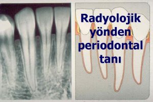
INTRODUCTION The radiograph is a valuable aid in the diagnosis of periodontal diseases, determination of prognosis and evaluation of the outcome of treatment.

USES OF RADIOGRAPHS Assess the extent of bone loss & furcation involvement. Determines the presence of any secondary local causative factor. Assists in treatment planning. Evaluates treatment measure particularly following guided tissue regeneration.

RADIOGRAPHIC PROJECTIONS USED TO ASSESS THE PERIODONTIUM. INCLUDES: Paralleling technique – periapical. Bitewings technique - normally for posterior teeth. Dental Panoramic Radiographs where there is pocketing greater than 5 mm in depth. Digital Radiography – Including Subtraction Radiography & Densitometric Image Analysis.

PERIAPICAL RADIOGRAPHY Two intraoral projection techniques may be used for periapical radiography. *Paralleling technique. *Bisecting-angle technique. Paralleling technique: The x-ray film is supported parallel to the long axis of the teeth and the central ray of the x-ray beam is directed at right angles to the teeth and film.

Bisecting-Angle technique: Here the film is positioned as possible to the lingual surface of the teeth, resting in the palate (or) in the floor of the mouth. The plane of the film and the long axis of the teeth form an angle, with its apex at the point where the film is in contact with the teeth. This angle is bisected by an imaginary line & two congruent angles are formed. A central ray will bisect the imaginary line which is perpendicular to the imaginary bisector.

THE BEST TECHNIQUE FOR DIAGNOSIS OF PERIODONTAL DISEASE Paralleling technique: It will demonstrate more accurately the features of Periodontites. It provides a better view of alveolar margin & reveals the actual depth of periodontal lesion in relation to root of the tooth. Bisecting angle technique: It shows greater destruction of the alveolar bone than is actually present, because the central ray is directed obliquely to the long axis of the teeth, which provides dimensional distortion. Hence the Paralleling technique is the best for evaluating periodontal disease.

COMPARISION OF BISECTING-ANGLE TECHNIQUE &PARALLELING TECHNIQUE: Bisecting-angle technique Paralleling technique

RADIOGRAPHIC ARTIFACTS Variation in technique, exposure, development time, type of film & angulations. Artifacts due to angulation: Long cone paralleling technique projects the realistic image of the level of the alveolar bone. Bisection of the angulation technique increases the projection and makes the bone margin closer to crown. Level of the facial bone margin is distorted more than the lingual bone margin. Shifting the cone mesialy or distally with the same horizontal plane , shows change in the shape of the interdental bone in the radiograph.

LONG CONE PARALLELING & BISECTION ANGLE TECHNIQUE Comparision Long cone paralleling technique. Bisection angle technique.

COMMON RADIOGRAFIC ARTIFACTS Light radiographs: *Processing errors -Excessive fixation. -Contaminated developer. *Underexposure -Insufficient time. -Film-source distance too great. Light radiographs-Insufficent exposure

Dark radiograph: : *Processing error -Overdevelopment. -Accidental exposure to light. *overexposure -Excessive time -Film-source distance too short. Overexposure

Insufficient contrast: -Under development. -Underexposure. Film fog: -Light leaks -Overdevelopment. Light spots: -Film contaminated with fixer before processing. Yellow or Brown staining: -Insufficient washing. -Depleted fixer. Light spot

NORMAL INTERDENTAL SEPTA . The interdental septum normally presents a thin radiopaque border, adjacent to the periodontal ligament is referred to as lamina dura. • It appears as a continuous white line, it is perforated by blood vessels, lymphatics & nerves which pass between the periodontal ligament & bone. Changes in the angulation of the x-ray beam produce considerable variations in the appearance. • The width & shape of the interdental septum and the angle of the crest normally vary to the convexity of the proximal tooth surface & the level of the cemento-enamel junction of the approximating teeth.

Crest of the interdental septum normally parallel to the line drawn between the cementoenamal junction of adjacent teeth

NORMAL RADIOGRAPHIC FEATURES 11 2 3 4 6 5 7 1 -dentin, 2 -enamel, 3 -pulp chamber, 4 -periodontal ligament, 5 -lamina dura, 6 -pulpcanal, 7 -cancellous bone

ADEQUATE ANGULATION OF PERIAPICAL RADIOGRAPH Prichard established four criteria: Radiograph should show the tips of the molar cups with little or none of the occlusal surface showing. Enamel caps & pulp chambers should be distinct. Interproximal spaces should be open. Proximal contacts should not overlap unless teeth are out of line anatomically.

BONE DESTRUCTION IN PERIODONTAL DISEASE • Radiograph does not reveal minor destructive changes in the bone. • The earliest signs of periodontal disease must be detected clinically. • Radiographic image tends to show less severe bone loss than that actually present. • The difference between the alveolar crest height & radiographic appearance ranges from 0 to 1. 6 mm.

AMOUNT OF BONE LOSS • Radiograph shows the amount of remaining bone than the amount lost. • The amount of bone loss is determined by the difference between the physiologic bone level of the patient & the height of the remaining bone. : • The distance from the cementoenamel junction to the alveolar crest seems to be 2 mm. DISTRIBUTION OF BONE LOSS. • It points to the location of destructive local factors in different areas of the mouth.

PATTERN OF BONE DESTRUCTION Horizontal bone loss: • The bone is reduced in height but the bone margin remains roughly perpendicular to the tooth surface. Vertical (or) Angular defects: • It occurs in oblique direction leaving a hollowed out trough in the bone alongside the root. • They are classified on the basis of number of osseous walls as One , Two & Three wall defect. • They are the concavities in the crest of the interdental bone.

GENERALISED HORIZONTAL BONE LOSS

Osseous craters: • They are the concavities in the crest of the interdental bone. • Guttapercha packed around the teeth increases the usefulness of the radiograph for detecting the morphologic changes of osseous craters & involvement of the facial & lingual surfaces. Reversed Architecture: • Produced by loss of interdental bone including the facial planes, lingual planes, without loss of radicular bone.

GENERAL RADIOGRAPHIC CHANGES IN PERIODONTITIS Fuzziness & a break in the continuity of the lamina dura at the mesial or distal aspect of the crest of the interdental septum -earliest radiographic change. Wedge-shaped radiolucent area is formed at the mesial or distal aspect of the crest of the septal bone. Finger like projection (radiolucent) extends across the crest into the septum. The height of the interdental septum is progressively reduced.

Normal appearance of interdental septa Excessive destruction Severe bone loss Fuzziness &break in laminadura

EARLY PERIODONTITIS • Fuzziness and break in the continuity of the lamina dura of the interdental septum can be seen. • It results from the extension of the gingival inflammation in to the bone, causing widening of vessel channels and reduction in calcified tissue.

MODERATE PERIODONTITIS Horizontal bone loss Local Or general Mild, moderate& severe bone loss Vertical bone loss Interproximal crater Infrabony defect Horizontal bone loss Both the buccal & lingual bone have been resorbed. , Localized bone loss Generalized bone loss

Vertical osseous defects • Divided into two types: . Interproximal crater. Infrabony defect Interproximal crater: Is a two walled trough like depression that formed in the crest of the interdental bone between adjacent teeth. Craters are detectable at about 1 mm deep. An Interproximal crater, seen through the defect between the buccal and lingual cortical plates

Infrabony defect: Is a vertical deformity within the bone that extends apically along the root from the alveolar crest. A twowalled infrabony defect-has one side wall remaining and one side wall lost. A two-walled infrabony defecthas one side wall remaning and one side wall lost.

Bony pockets: - • Osseous defects sometimes form in the vestibular or lingual bone over the roots of the tooth – Bony pockets. • Blunt silver points assist in locating the base of the pocket.

ADVANCED PERIODONTITIS Slightest change in the furcation area can be investigated clinically. Radiographic detection: Diminished radiodensity in the furcation area. Marked bone loss in relation to a single molar root – furcation involvement is there. Furcation involvement

RADIOGRAPHIC CHANGES IN AGGRESSIVE PERIODONTITIS • Localized form-Localized angular bone loss in the region of the first molars & incisors. • Generalized form-Involves most of the dentition -Usually between ages of 20&30 yrs. Localized form -In addition to first molar & incisors, canine, premolars & second molars are involved. -Angular bone loss of alveolar bone that may progress to tooth loss.

RADIOGRAPHIC APPEARANCE OF THE PERIODONTAL ABSCESS Appears as a discrete area of radiolucency along the lateral aspect of the root. Early stage- break in the lamina dura. clinically-Tender on percussion. Chronic stage-Circular&dark areas around the apices of the teeth.

RADIOGRAPHIC CHANGES IN TRAUMA FROM OCCLUSION There are changes in lamina dura, morphology of alveolar crest, width of the periodontal space & density of the surrounding cancellous bone. . . Injury phase of trauma from occlusion produces a loss of the lamina dura resulting in widening of periodontal ligament. . Repair phase of trauma from occlusion-Attempts to strengthen the periodontal structures. . More advanced traumatic lesions-Result in deep angular bone loss. Root resorption may be due to excessive forces on the periodontium caused by orthodontic appliance.

WIDENED PERIODONTAL SPACE CAUSED BY TRAUMA FROM OCCLUSION

PERIODONTITIS DUE TO LOCAL IRRITANTS Calculus: - Irregular Radiopaque area around the cervical area of the teeth. Defective restoration: - Radiographically it reveals poor contours, open contacts, overhanging margins & caries. Over hanging amalgam restoration-results in alveolar bone loss

SKELETAL DISTURBANCES MANIFESTED IN THE JAWS Ostetis fibrosa cystica: -Develops in advanced primary or secondary hyperparathyroidism. -Appears as scattered radiolucent areas throughout the jaws. Paget’s disease: -Trabecular pattern is altered. -Lamina dura absent. Fibrous displasia: -Small radiolucent area at the root apex.

-There may be extensive radiolucent area with irregularly arranged trabecular pattern. Paget’s disesae Fibrous dysplasia

Scleroderma -The periodontal ligament is uniformly widened at the expense of surrounding alveolar bone. Scleroderma showing uniform widening of periodontal ligament

RADIOGRAPHIC APPEARANCE IN HYPERPARATHYROIDISM Thinning of cortical boundaries which occurs in the jaws. Loss of Lamina dura-Tapered appearance of the root Brown tumor occurs late in the disease. Loss of lamina dura Brown tumor

LIMITATION OF RADIOGRAPHS Radiographs do not indicate the rate or presence of active bone or attachment loss. Radiographs do not indicate whether past episodes of destruction and healing occurred. 30% to 60% of mineral content of bone should be lost in order to visualize change in the radiographs. Radiographs provide a restricted two dimensional representation of the three dimensional anatomy. Do not indicate the depth of vertical defects. Do not indicate the extent of involvement on the facial or lingual surfaces.

ADVANCED RADIOGRAPHIC TCHNIQUES Xeroradiographs Uses the Xerographic copying process to record x -ray images. It has a property of ‘Edge Enhancement’ by which fine structures eg- bone trabecular & areas of suitable density differences made visible. The images are recorded on selenium alloy photo receptive plates.

Advantages *Greater imaging speed. *Increased speed of interpretation. *Does not require use of silver. *Lower radiation exposure.

SUBTRACTION RADIOGRAPHY Helps in assessment of attachmentloss in three dimension. A standardized radiographic image is obtained before the appearance of an anatomical change & is subtracted from a subsequent standardized radiograph. The radiolucent subtraction image is that of the isolated structure which has undergone the change. Greater improvement in this technique-with the combination of the video & computer technology.

Advantages . Small osseous lesions are detected. • A high degree of correlation between changes in alveolar bone is determined. MAGNETIC RESONANCE IMAGING (MRI) Patient is placed in a large magnet & electromagnetic energy temporarily changes the alignment and orientation of hydrogen proton within the body. The area being examined is then subjected to radio frequency waves. Using this image a computer can generate image.

COMPUTED TOMOGRAPHY (CT) CT scanner uses x-rays to produce sectional or slice images. The radiographic film has sensitive gas detectors. The detector measures the intensity of the x-ray beam emerging from the patient and convert this into digital data which are stored and can be manipulated by the computer. This numerical information is converted in to a gray scale representing different tissue densities, thus allowing a visual image to be generated.

RADIOVISIOGRAPHY (RVG) RVG is used in detecting the bony lesion & determining the difference in identification of buccal and lingual lesion. Defects on the lingual area will be depicted than those on the buccal. It demonstrates superiority in its diagnostic accuracy. It has a better diagnostic value in the detection of early pathological conditions. .

 Diagnosis of periodontal disease
 Iatrogenic factors in periodontal disease
 Periodontal disease
 Explain nursing process
 Medical diagnosis and nursing diagnosis difference
 Types of nursing diagnosis
 Objectives of nursing process
 Perbedaan diagnosis gizi dan diagnosis medis
 Mandible x ray positioning towne's
 Why sims position for enema
 Off center grid error
 Film hopper in radiography
 Dental radiography ppt
 Outer canthus
 Sid and oid in radiography
 Alveolar bone
 Radiographic film
 Guide shoe mark artifact
 Reverse towne projection uses
 Radiographic films
 Absorption unsharpness
 Dacrocystogram
 Nursing diagnosis for vision impairment
 Nursing diagnosis for meniere's disease
 Behcet disease diagnosis
 Bharathi viswanathan
 Principles of scaling and root planing
 Perimylolysis
 Plak boyayıcı ajanlar
 Synonyms of periodontal ligament
 Plaque index
 Russell periodontal index
 Fases del tratamiento periodontal
 Surgical phase periodontal therapy
 Lanap perio
 Rationale for periodontal treatment
 Transseptal lifler
 Paranky
 Glickman's concept
 Periodontal management of medically compromised patients
 Akut streptokokal gingivitis
 Técnica step back (técnica de retroceso)
 Factores de patogenicidad de helicobacter pylori
 Principal fibres of pdl
 Periodontal dokuların embriyolojisi
 Aot cyst
 Periapical cemento-osseous dysplasia
 Periodontal abscess
