Pipelined Processor Design COE 301 Computer Organization Prof

- Slides: 70
Pipelined Processor Design COE 301 Computer Organization Prof. Aiman El-Maleh College of Computer Sciences and Engineering King Fahd University of Petroleum and Minerals [Adapted from slides of Dr. M. Mudawar, COE 301, KFUPM]
Presentation Outline v Pipelining versus Serial Execution v Pipelined Datapath and Control v Pipeline Hazards v Data Hazards and Forwarding v Load Delay, Hazard Detection, and Stall v Control Hazards v Delayed Branch and Dynamic Branch Prediction Pipelined Processor Design COE 301 – KFUPM slide 2
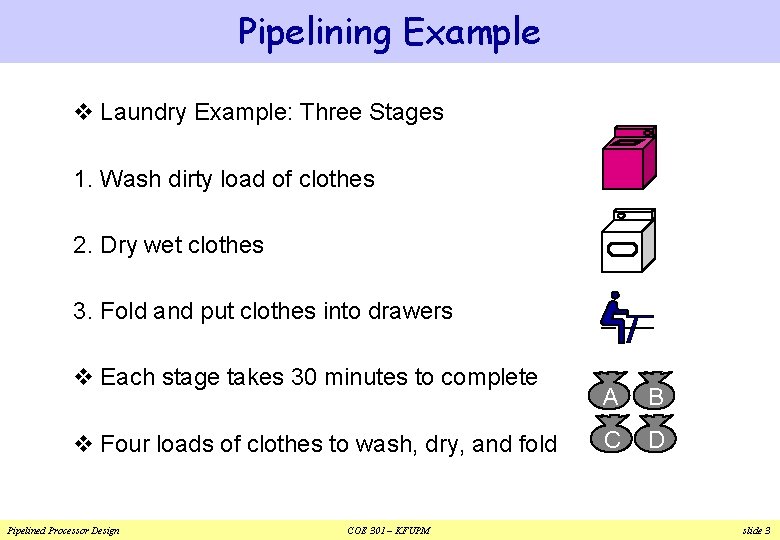
Pipelining Example v Laundry Example: Three Stages 1. Wash dirty load of clothes 2. Dry wet clothes 3. Fold and put clothes into drawers v Each stage takes 30 minutes to complete v Four loads of clothes to wash, dry, and fold Pipelined Processor Design COE 301 – KFUPM A B C D slide 3
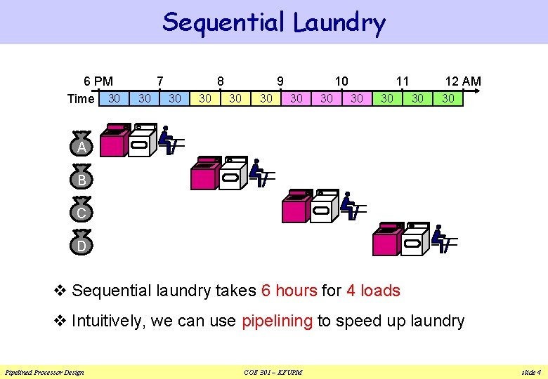
Sequential Laundry 6 PM Time 30 7 30 8 30 30 9 30 30 10 30 30 11 30 30 12 AM 30 30 A B C D v Sequential laundry takes 6 hours for 4 loads v Intuitively, we can use pipelining to speed up laundry Pipelined Processor Design COE 301 – KFUPM slide 4
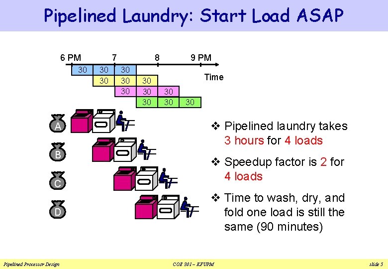
Pipelined Laundry: Start Load ASAP 6 PM 30 A B C D Pipelined Processor Design 7 30 30 8 30 30 30 9 PM Time 30 30 30 v Pipelined laundry takes 3 hours for 4 loads v Speedup factor is 2 for 4 loads v Time to wash, dry, and fold one load is still the same (90 minutes) COE 301 – KFUPM slide 5
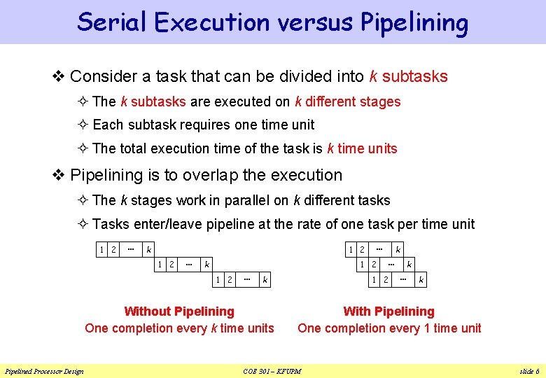
Serial Execution versus Pipelining v Consider a task that can be divided into k subtasks ² The k subtasks are executed on k different stages ² Each subtask requires one time unit ² The total execution time of the task is k time units v Pipelining is to overlap the execution ² The k stages work in parallel on k different tasks ² Tasks enter/leave pipeline at the rate of one task per time unit 1 2 … k 1 2 … 1 2 k Without Pipelining One completion every k time units Pipelined Processor Design … k … 1 2 k … k With Pipelining One completion every 1 time unit COE 301 – KFUPM slide 6
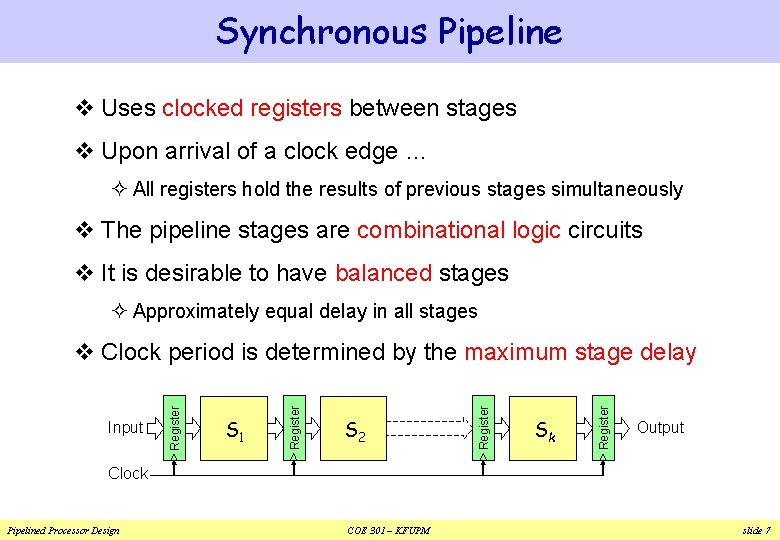
Synchronous Pipeline v Uses clocked registers between stages v Upon arrival of a clock edge … ² All registers hold the results of previous stages simultaneously v The pipeline stages are combinational logic circuits v It is desirable to have balanced stages ² Approximately equal delay in all stages Sk Register S 2 Register S 1 Register Input Register v Clock period is determined by the maximum stage delay Output Clock Pipelined Processor Design COE 301 – KFUPM slide 7
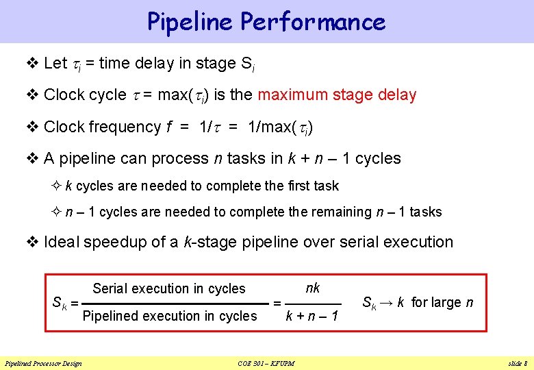
Pipeline Performance v Let ti = time delay in stage Si v Clock cycle t = max(ti) is the maximum stage delay v Clock frequency f = 1/t = 1/max(ti) v A pipeline can process n tasks in k + n – 1 cycles ² k cycles are needed to complete the first task ² n – 1 cycles are needed to complete the remaining n – 1 tasks v Ideal speedup of a k-stage pipeline over serial execution Sk = Pipelined Processor Design Serial execution in cycles Pipelined execution in cycles nk = k+n– 1 COE 301 – KFUPM Sk → k for large n slide 8
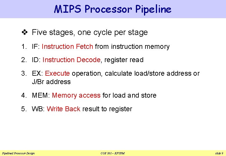
MIPS Processor Pipeline v Five stages, one cycle per stage 1. IF: Instruction Fetch from instruction memory 2. ID: Instruction Decode, register read 3. EX: Execute operation, calculate load/store address or J/Br address 4. MEM: Memory access for load and store 5. WB: Write Back result to register Pipelined Processor Design COE 301 – KFUPM slide 9
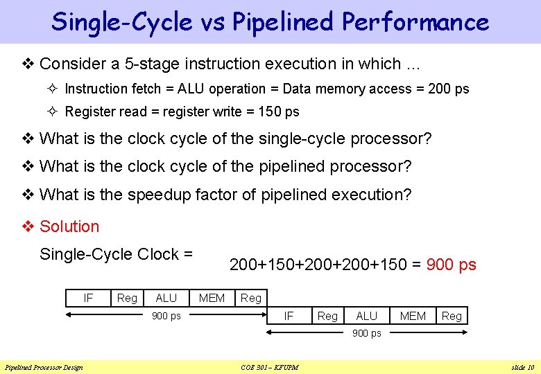
Single-Cycle vs Pipelined Performance v Consider a 5 -stage instruction execution in which … ² Instruction fetch = ALU operation = Data memory access = 200 ps ² Register read = register write = 150 ps v What is the clock cycle of the single-cycle processor? v What is the clock cycle of the pipelined processor? v What is the speedup factor of pipelined execution? v Solution Single-Cycle Clock = IF Reg ALU 900 ps 200+150+200+150 = 900 ps MEM Reg IF Reg ALU MEM Reg 900 ps Pipelined Processor Design COE 301 – KFUPM slide 10
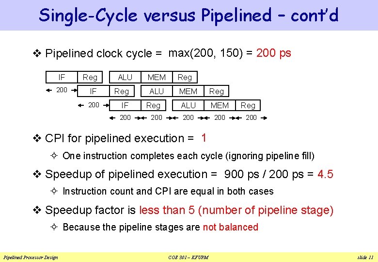
Single-Cycle versus Pipelined – cont’d v Pipelined clock cycle = max(200, 150) = 200 ps IF Reg 200 IF 200 ALU Reg IF 200 MEM Reg ALU MEM 200 Reg 200 v CPI for pipelined execution = 1 ² One instruction completes each cycle (ignoring pipeline fill) v Speedup of pipelined execution = 900 ps / 200 ps = 4. 5 ² Instruction count and CPI are equal in both cases v Speedup factor is less than 5 (number of pipeline stage) ² Because the pipeline stages are not balanced Pipelined Processor Design COE 301 – KFUPM slide 11
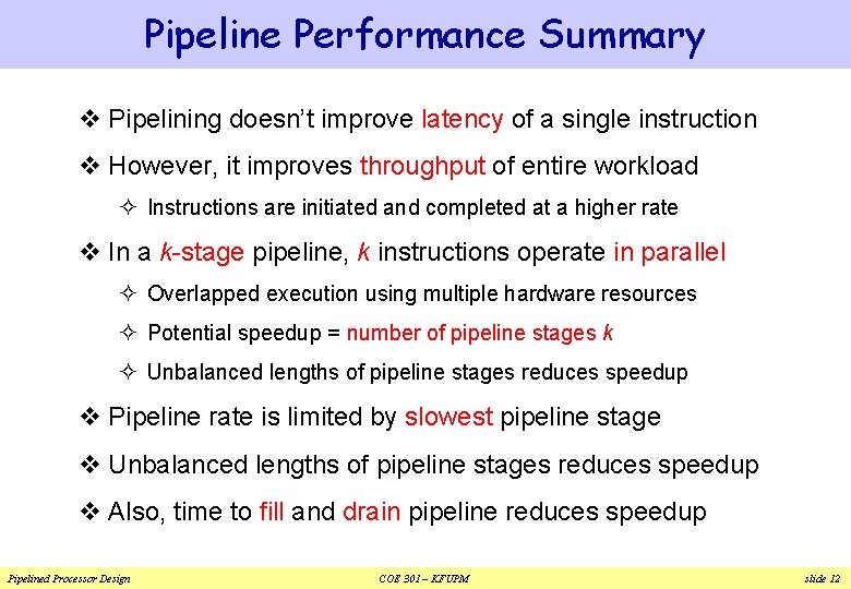
Pipeline Performance Summary v Pipelining doesn’t improve latency of a single instruction v However, it improves throughput of entire workload ² Instructions are initiated and completed at a higher rate v In a k-stage pipeline, k instructions operate in parallel ² Overlapped execution using multiple hardware resources ² Potential speedup = number of pipeline stages k ² Unbalanced lengths of pipeline stages reduces speedup v Pipeline rate is limited by slowest pipeline stage v Unbalanced lengths of pipeline stages reduces speedup v Also, time to fill and drain pipeline reduces speedup Pipelined Processor Design COE 301 – KFUPM slide 12
Next. . . v Pipelining versus Serial Execution v Pipelined Datapath and Control v Pipeline Hazards v Data Hazards and Forwarding v Load Delay, Hazard Detection, and Stall v Control Hazards v Delayed Branch and Dynamic Branch Prediction Pipelined Processor Design COE 301 – KFUPM slide 13
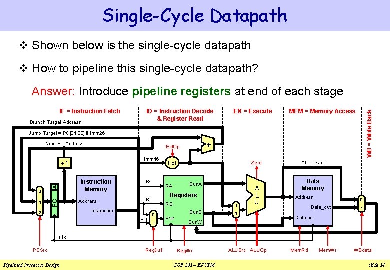
Single-Cycle Datapath v Shown below is the single-cycle datapath v How to pipeline this single-cycle datapath? Answer: Introduce pipeline registers at end of each stage Branch Target Address ID = Instruction Decode & Register Read EX = Execute MEM = Memory Access WB = Write Back IF = Instruction Fetch Jump Target = PC[31: 28] ‖ Imm 26 Next PC Address Imm 16 +1 1 00 Instruction Memory Address PC 0 Rs Rd Zero Ext Bus. A RA Registers Rt Instruction 2 + Ext. Op RB 0 1 1 Bus. B RW A L U 0 Bus. W ALU result Data Memory Address 0 Data_out 1 Data_in clk PCSrc Pipelined Processor Design Reg. Dst Reg. Wr COE 301 – KFUPM ALUSrc ALUOp Mem. Rd Mem. Wr WBdata slide 14
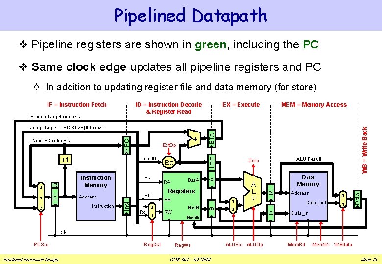
Pipelined Datapath v Pipeline registers are shown in green, including the PC v Same clock edge updates all pipeline registers and PC ² In addition to updating register file and data memory (for store) ID = Instruction Decode & Register Read IF = Instruction Fetch Branch Target Address EX = Execute MEM = Memory Access Rd BTA RB 0 1 RW 1 Bus. B A L U 0 Bus. W Address 0 Data_out 1 Data Registers Data Memory R PC Bus. A ALU Result Zero D Instruction 2 RA Rt Address Ext B 00 1 Rs Inst 0 Instruction Memory Imm 16 +1 + Ext. Op A NPC Next PC Address WB = Write Back Jump Target = PC[31: 28] ‖ Imm 26 Data_in clk PCSrc Pipelined Processor Design Reg. Dst Reg. Wr COE 301 – KFUPM ALUSrc ALUOp Mem. Rd Mem. Wr WBdata slide 15
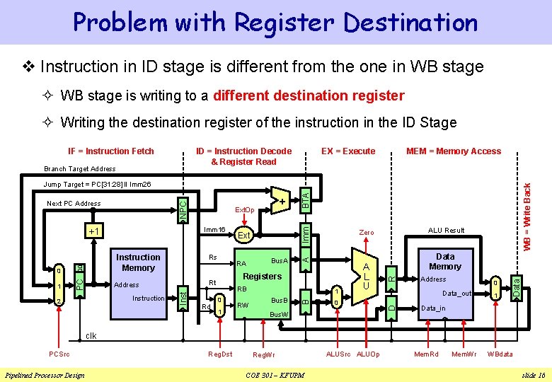
Problem with Register Destination v Instruction in ID stage is different from the one in WB stage ² WB stage is writing to a different destination register ² Writing the destination register of the instruction in the ID Stage IF = Instruction Fetch ID = Instruction Decode & Register Read Branch Target Address EX = Execute MEM = Memory Access Rd BTA RB 0 1 RW 1 Bus. B A L U 0 Bus. W Address 0 Data_out 1 Data Registers Data Memory R PC Bus. A ALU Result Zero D Instruction 2 RA Rt Address Ext B 00 1 Rs Inst 0 Instruction Memory Imm 16 +1 + Ext. Op A NPC Next PC Address WB = Write Back Jump Target = PC[31: 28] ‖ Imm 26 Data_in clk PCSrc Pipelined Processor Design Reg. Dst Reg. Wr COE 301 – KFUPM ALUSrc ALUOp Mem. Rd Mem. Wr WBdata slide 16
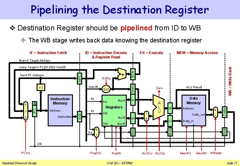
Pipelining the Destination Register v Destination Register should be pipelined from ID to WB ² The WB stage writes back data knowing the destination register IF = Instruction Fetch ID = Instruction Decode & Register Read Branch Target Address EX = Execute MEM = Memory Access BTA Bus. B RW Bus. W 0 Rd 2 Rd 0 1 0 Data_out 1 Data 1 Address Data_in Rd 4 RB Data Memory R Rt A L U D PC Bus. A Rd 3 Instruction RA ALU Result Zero Registers Address 2 Ext B 00 1 Rs Inst 0 Instruction Memory Imm 16 +1 + Ext. Op A NPC Next PC Address WB = Write Back Jump Target = PC[31: 28] ‖ Imm 26 clk PCSrc Pipelined Processor Design Reg. Dst Reg. Wr COE 301 – KFUPM ALUSrc ALUOp Mem. Rd Mem. Wr WBdata slide 17
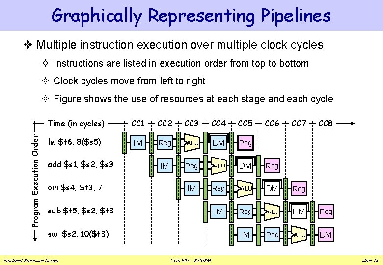
Graphically Representing Pipelines v Multiple instruction execution over multiple clock cycles ² Instructions are listed in execution order from top to bottom ² Clock cycles move from left to right Program Execution Order ² Figure shows the use of resources at each stage and each cycle Time (in cycles) CC 1 CC 2 CC 3 CC 4 CC 5 lw $t 6, 8($s 5) IM Reg ALU DM Reg IM Reg ALU DM add $s 1, $s 2, $s 3 ori $s 4, $t 3, 7 sub $t 5, $s 2, $t 3 sw $s 2, 10($t 3) Pipelined Processor Design COE 301 – KFUPM CC 6 CC 7 CC 8 slide 18
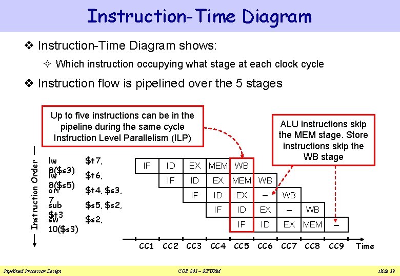
Instruction-Time Diagram v Instruction-Time Diagram shows: ² Which instruction occupying what stage at each clock cycle v Instruction flow is pipelined over the 5 stages Instruction Order Up to five instructions can be in the pipeline during the same cycle Instruction Level Parallelism (ILP) lw 8($s 3) lw 8($s 5) ori 7 sub $t 3 sw 10($s 3) $t 7, $t 6, IF $t 4, $s 3, Pipelined Processor Design ID EX IF ID EX – WB IF ID EX MEM – CC 5 CC 6 CC 7 CC 8 CC 9 $s 5, $s 2, CC 1 ALU instructions skip the MEM stage. Store instructions skip the WB stage CC 2 CC 3 MEM WB CC 4 COE 301 – KFUPM MEM WB Time slide 19
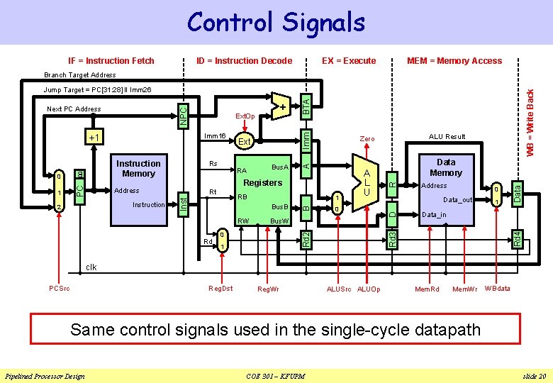
Control Signals IF = Instruction Fetch ID = Instruction Decode EX = Execute MEM = Memory Access Branch Target Address BTA Bus. B RW Bus. W 0 Rd 2 Rd 0 1 0 Data_out 1 Data 1 Address Data_in Rd 4 RB R Rt A L U Data Memory D Bus. A Rd 3 PC Instruction RA ALU Result Zero Registers Address 2 Ext B 00 1 Rs Inst 0 Instruction Memory Imm 16 +1 + Ext. Op A NPC Next PC Address WB = Write Back Jump Target = PC[31: 28] ‖ Imm 26 clk PCSrc Reg. Dst Reg. Wr ALUSrc ALUOp Mem. Rd Mem. Wr WBdata Same control signals used in the single-cycle datapath Pipelined Processor Design COE 301 – KFUPM slide 20
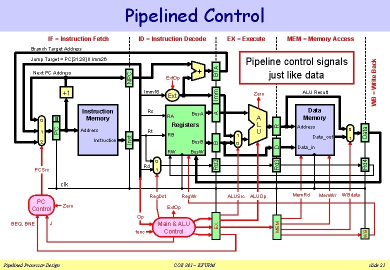
Pipelined Control IF = Instruction Fetch ID = Instruction Decode EX = Execute MEM = Memory Access Branch Target Address Bus. W 0 Rd 2 Rd 0 1 R 0 Data_out 1 Data Bus. B Address Data_in Rd 4 1 RW PCSrc BTA RB D Rt A L U Data Memory Rd 3 Instruction Bus. A RA ALU Result Zero Registers Address 2 Ext B PC Rs Inst 00 1 Instruction Memory Imm 16 +1 0 + Ext. Op A NPC Next PC Address WB = Write Back Pipeline control signals just like data Jump Target = PC[31: 28] ‖ Imm 26 clk PC Control Reg. Dst Zero Reg. Wr ALUSrc Mem. Rd ALUOp Mem. Wr WBdata Ext. Op Pipelined Processor Design Main & ALU Control COE 301 – KFUPM WB func MEM J EX Op BEQ, BNE slide 21
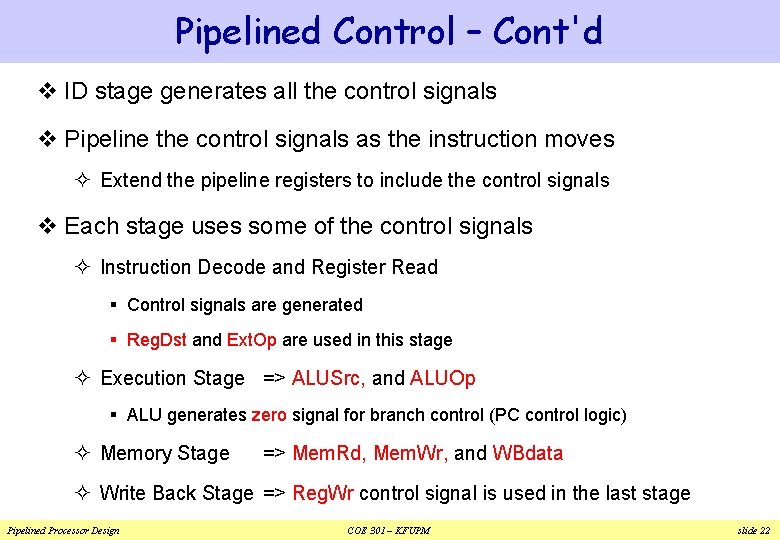
Pipelined Control – Cont'd v ID stage generates all the control signals v Pipeline the control signals as the instruction moves ² Extend the pipeline registers to include the control signals v Each stage uses some of the control signals ² Instruction Decode and Register Read § Control signals are generated § Reg. Dst and Ext. Op are used in this stage ² Execution Stage => ALUSrc, and ALUOp § ALU generates zero signal for branch control (PC control logic) ² Memory Stage => Mem. Rd, Mem. Wr, and WBdata ² Write Back Stage => Reg. Wr control signal is used in the last stage Pipelined Processor Design COE 301 – KFUPM slide 22
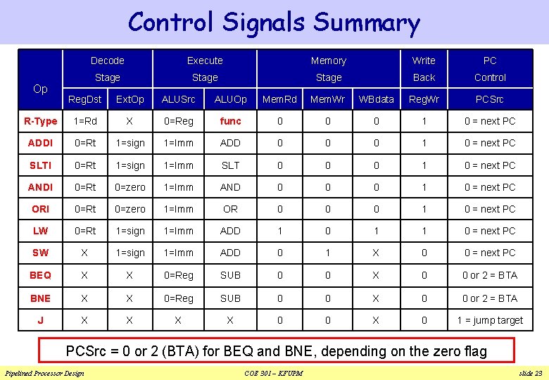
Control Signals Summary Op Decode Execute Memory Write PC Stage Back Control Reg. Dst Ext. Op ALUSrc ALUOp Mem. Rd Mem. Wr WBdata Reg. Wr PCSrc R-Type 1=Rd X 0=Reg func 0 0 0 1 0 = next PC ADDI 0=Rt 1=sign 1=Imm ADD 0 0 0 1 0 = next PC SLTI 0=Rt 1=sign 1=Imm SLT 0 0 0 1 0 = next PC ANDI 0=Rt 0=zero 1=Imm AND 0 0 0 1 0 = next PC ORI 0=Rt 0=zero 1=Imm OR 0 0 0 1 0 = next PC LW 0=Rt 1=sign 1=Imm ADD 1 0 1 1 0 = next PC SW X 1=sign 1=Imm ADD 0 1 X 0 0 = next PC BEQ X X 0=Reg SUB 0 0 X 0 0 or 2 = BTA BNE X X 0=Reg SUB 0 0 X 0 0 or 2 = BTA J X X 0 0 X 0 1 = jump target PCSrc = 0 or 2 (BTA) for BEQ and BNE, depending on the zero flag Pipelined Processor Design COE 301 – KFUPM slide 23
Next. . . v Pipelining versus Serial Execution v Pipelined Datapath and Control v Pipeline Hazards v Data Hazards and Forwarding v Load Delay, Hazard Detection, and Stall v Control Hazards v Delayed Branch and Dynamic Branch Prediction Pipelined Processor Design COE 301 – KFUPM slide 24
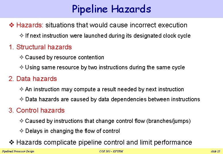
Pipeline Hazards v Hazards: situations that would cause incorrect execution ² If next instruction were launched during its designated clock cycle 1. Structural hazards ² Caused by resource contention ² Using same resource by two instructions during the same cycle 2. Data hazards ² An instruction may compute a result needed by next instruction ² Data hazards are caused by data dependencies between instructions 3. Control hazards ² Caused by instructions that change control flow (branches/jumps) ² Delays in changing the flow of control v Hazards complicate pipeline control and limit performance Pipelined Processor Design COE 301 – KFUPM slide 25
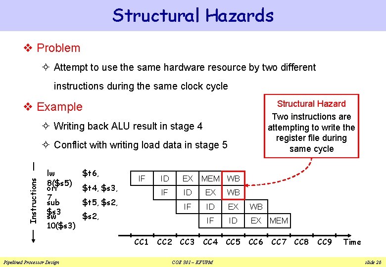
Structural Hazards v Problem ² Attempt to use the same hardware resource by two different instructions during the same clock cycle Structural Hazard Two instructions are attempting to write the register file during same cycle v Example ² Writing back ALU result in stage 4 Instructions ² Conflict with writing load data in stage 5 lw 8($s 5) ori 7 sub $s 3 sw 10($s 3) $t 6, $t 4, $s 3, IF $t 5, $s 2, EX IF ID EX WB IF ID EX MEM CC 4 CC 5 CC 6 CC 7 $s 2, CC 1 Pipelined Processor Design ID CC 2 CC 3 MEM WB COE 301 – KFUPM CC 8 CC 9 Time slide 26
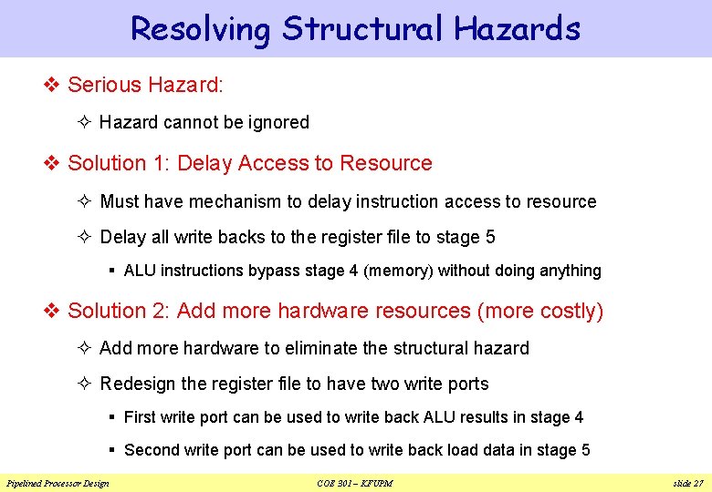
Resolving Structural Hazards v Serious Hazard: ² Hazard cannot be ignored v Solution 1: Delay Access to Resource ² Must have mechanism to delay instruction access to resource ² Delay all write backs to the register file to stage 5 § ALU instructions bypass stage 4 (memory) without doing anything v Solution 2: Add more hardware resources (more costly) ² Add more hardware to eliminate the structural hazard ² Redesign the register file to have two write ports § First write port can be used to write back ALU results in stage 4 § Second write port can be used to write back load data in stage 5 Pipelined Processor Design COE 301 – KFUPM slide 27
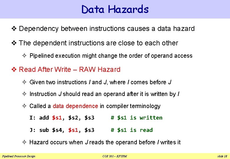
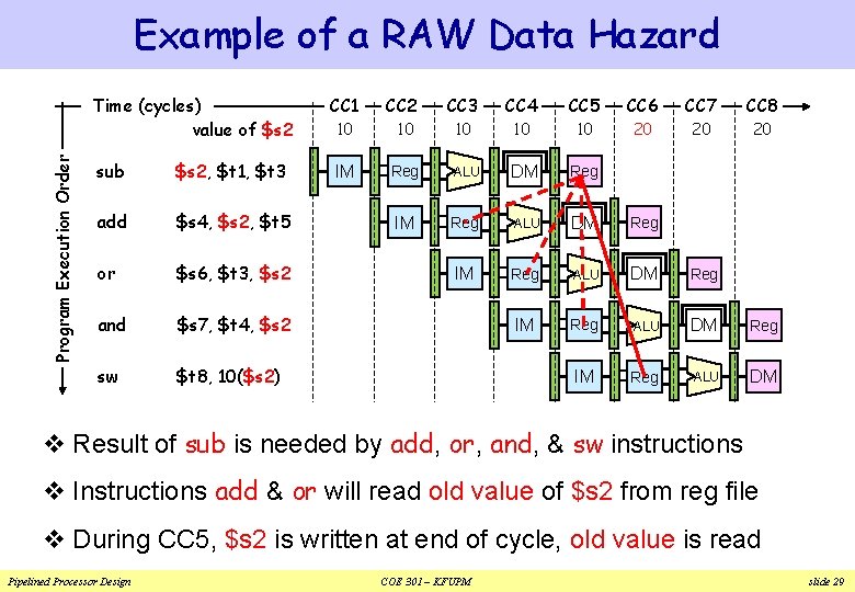
Data Hazards v Dependency between instructions causes a data hazard v The dependent instructions are close to each other ² Pipelined execution might change the order of operand access v Read After Write – RAW Hazard ² Given two instructions I and J, where I comes before J ² Instruction J should read an operand after it is written by I ² Called a data dependence in compiler terminology I: add $s 1, $s 2, $s 3 # $s 1 is written J: sub $s 4, $s 1, $s 3 # $s 1 is read ² Hazard occurs when J reads the operand before I writes it Pipelined Processor Design COE 301 – KFUPM slide 28
Example of a RAW Data Hazard Program Execution Order Time (cycles) value of $s 2 sub $s 2, $t 1, $t 3 add $s 4, $s 2, $t 5 or $s 6, $t 3, $s 2 and $s 7, $t 4, $s 2 sw $t 8, 10($s 2) CC 1 CC 2 CC 3 CC 4 CC 5 CC 6 CC 7 CC 8 10 10 10 20 20 20 IM Reg ALU DM Reg IM Reg ALU DM v Result of sub is needed by add, or, and, & sw instructions v Instructions add & or will read old value of $s 2 from reg file v During CC 5, $s 2 is written at end of cycle, old value is read Pipelined Processor Design COE 301 – KFUPM slide 29
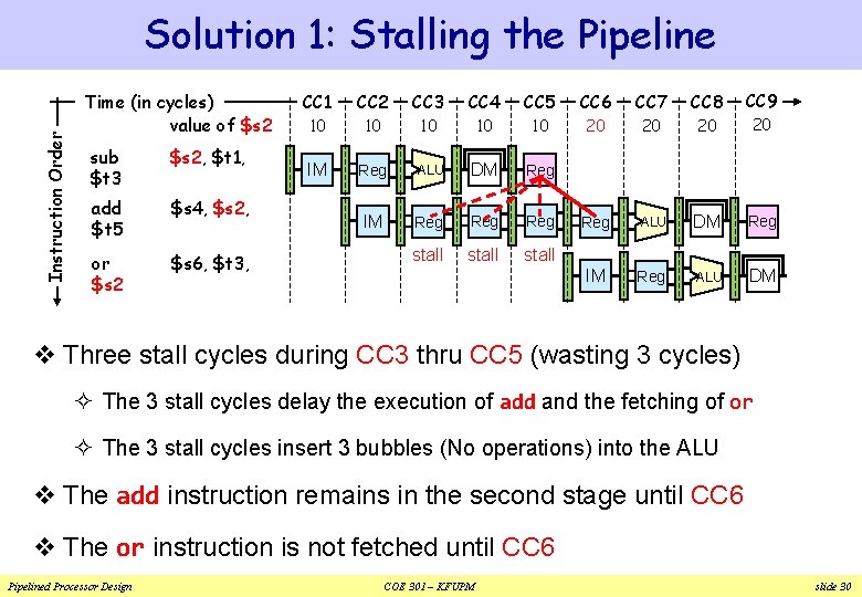
Instruction Order Solution 1: Stalling the Pipeline Time (in cycles) value of $s 2 sub $t 3 $s 2, $t 1, add $t 5 $s 4, $s 2, or $s 2 $s 6, $t 3, CC 1 CC 2 CC 3 CC 4 CC 5 CC 6 CC 7 CC 8 CC 9 10 10 10 20 20 IM Reg ALU DM Reg IM Reg Reg ALU DM Reg stall IM Reg ALU DM v Three stall cycles during CC 3 thru CC 5 (wasting 3 cycles) ² The 3 stall cycles delay the execution of add and the fetching of or ² The 3 stall cycles insert 3 bubbles (No operations) into the ALU v The add instruction remains in the second stage until CC 6 v The or instruction is not fetched until CC 6 Pipelined Processor Design COE 301 – KFUPM slide 30
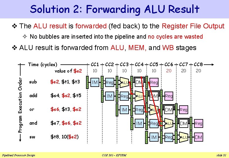
Solution 2: Forwarding ALU Result v The ALU result is forwarded (fed back) to the Register File Output ² No bubbles are inserted into the pipeline and no cycles are wasted Program Execution Order v ALU result is forwarded from ALU, MEM, and WB stages Time (cycles) value of $s 2 CC 1 CC 2 CC 3 CC 4 CC 5 CC 6 CC 7 CC 8 10 10 10 20 20 20 sub $s 2, $t 1, $t 3 IM Reg ALU DM Reg add $s 4, $s 2, $t 5 IM Reg ALU DM Reg or $s 6, $t 3, $s 2 IM Reg ALU DM Reg and $s 7, $s 6, $s 2 IM Reg ALU DM Reg sw $t 8, 10($s 2) IM Reg ALU DM Pipelined Processor Design COE 301 – KFUPM slide 31
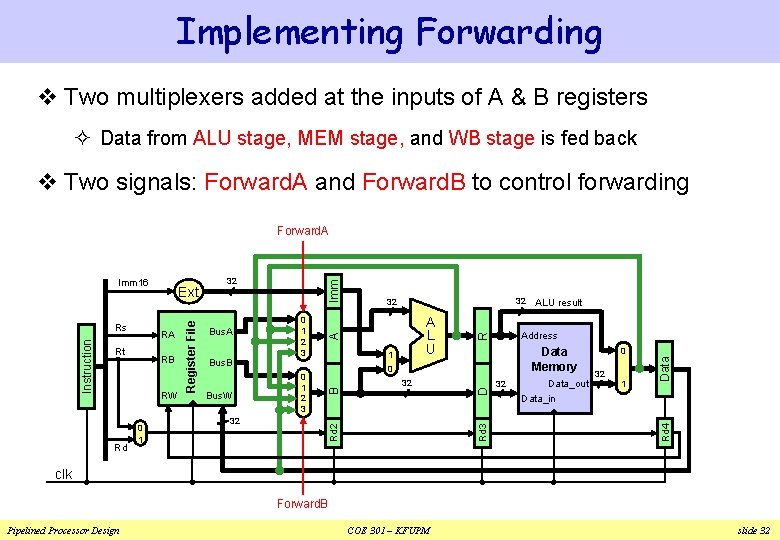
Implementing Forwarding v Two multiplexers added at the inputs of A & B registers ² Data from ALU stage, MEM stage, and WB stage is fed back v Two signals: Forward. A and Forward. B to control forwarding Forward. A Rd 0 1 Bus. W 32 Data Memory 0 32 32 Data_out 0 32 1 Data 1 Address R A Imm 0 1 2 3 A L U ALU result Data_in Rd 4 RW Bus. B 0 1 2 3 D RB Bus. A 32 32 Rd 3 Rt 32 B RA Register File Instruction Rs Ext Rd 2 Imm 16 clk Forward. B Pipelined Processor Design COE 301 – KFUPM slide 32
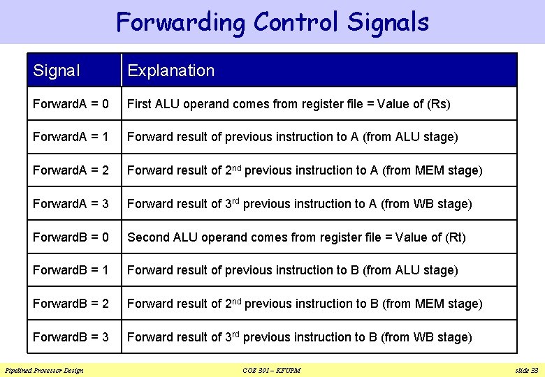
Forwarding Control Signals Signal Explanation Forward. A = 0 First ALU operand comes from register file = Value of (Rs) Forward. A = 1 Forward result of previous instruction to A (from ALU stage) Forward. A = 2 Forward result of 2 nd previous instruction to A (from MEM stage) Forward. A = 3 Forward result of 3 rd previous instruction to A (from WB stage) Forward. B = 0 Second ALU operand comes from register file = Value of (Rt) Forward. B = 1 Forward result of previous instruction to B (from ALU stage) Forward. B = 2 Forward result of 2 nd previous instruction to B (from MEM stage) Forward. B = 3 Forward result of 3 rd previous instruction to B (from WB stage) Pipelined Processor Design COE 301 – KFUPM slide 33
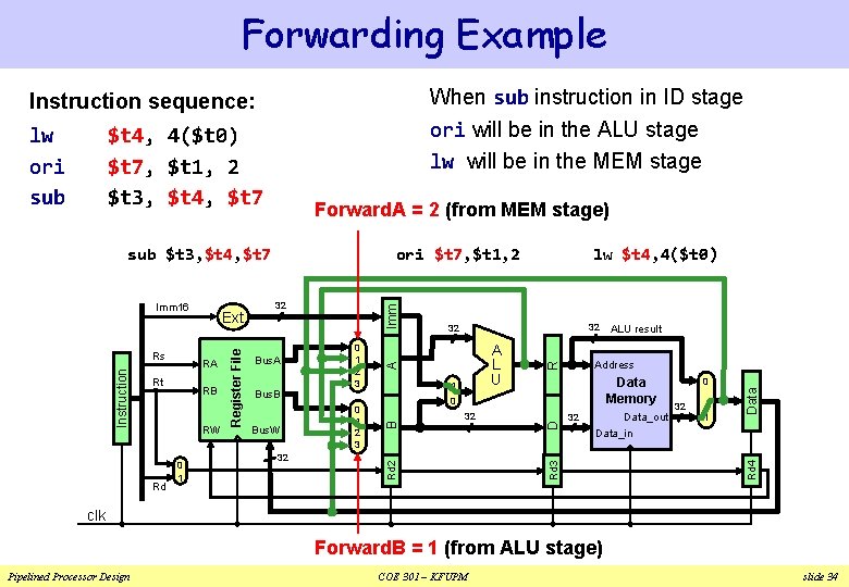
Forwarding Example Instruction sequence: When sub instruction in ID stage lw ori sub ori will be in the ALU stage lw will be in the MEM stage $t 4, 4($t 0) $t 7, $t 1, 2 $t 3, $t 4, $t 7 Forward. A = 2 (from MEM stage) RW Rd 0 1 Bus. W 32 1 Address R A Imm 0 1 2 3 A L U Data Memory 0 32 ALU result Data_out 32 0 32 1 Data Bus. B 0 1 2 3 32 32 Data_in Rd 4 RB Bus. A lw $t 4, 4($t 0) D Rt 32 B RA Register File Instruction Rs Ext Rd 2 Imm 16 ori $t 7, $t 1, 2 Rd 3 sub $t 3, $t 4, $t 7 clk Forward. B = 1 (from ALU stage) Pipelined Processor Design COE 301 – KFUPM slide 34
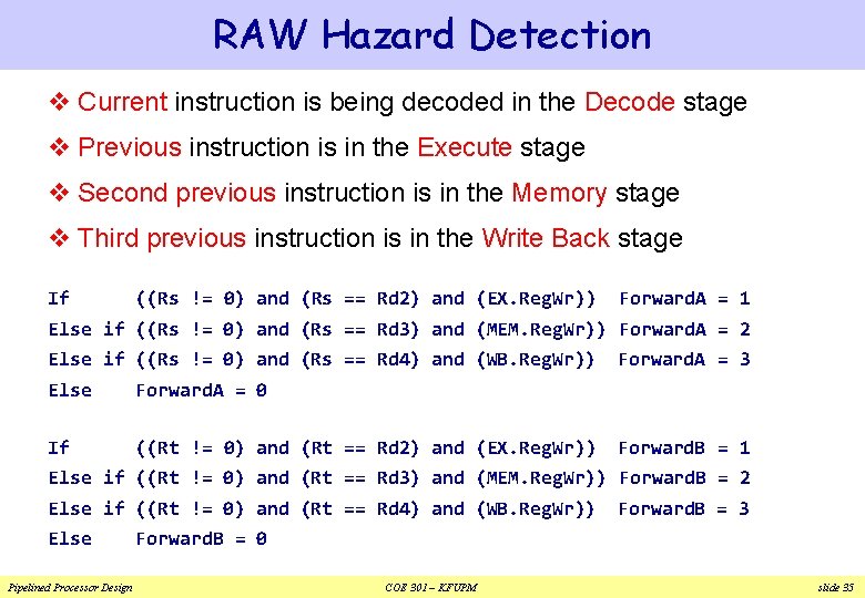
RAW Hazard Detection v Current instruction is being decoded in the Decode stage v Previous instruction is in the Execute stage v Second previous instruction is in the Memory stage v Third previous instruction is in the Write Back stage If ((Rs != 0) and (Rs == Rd 2) and (EX. Reg. Wr)) Forward. A = 1 Else if ((Rs != 0) and (Rs == Rd 3) and (MEM. Reg. Wr)) Forward. A = 2 Else if ((Rs != 0) and (Rs == Rd 4) and (WB. Reg. Wr)) Else Forward. A = 0 If ((Rt != 0) and (Rt == Rd 2) and (EX. Reg. Wr)) Forward. A = 3 Forward. B = 1 Else if ((Rt != 0) and (Rt == Rd 3) and (MEM. Reg. Wr)) Forward. B = 2 Else if ((Rt != 0) and (Rt == Rd 4) and (WB. Reg. Wr)) Else Pipelined Processor Design Forward. B = 3 Forward. B = 0 COE 301 – KFUPM slide 35
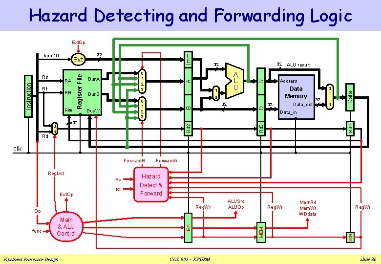
Hazard Detecting and Forwarding Logic Ext. Op Rd 32 0 1 R 0 0 1 2 3 Bus. W Data Memory 32 Data_out 32 0 32 1 Data Imm 1 Address Data_in Rd 4 RW Bus. B D RB A L U ALU result Rd 3 Rt 0 1 2 3 Bus. A 32 32 A RA 32 Rd 2 Instruction Rs Register File Ext B Imm 16 clk Forward. B Ext. Op Rt Hazard Detect & Forward Reg. Wr func Main & ALU Control Pipelined Processor Design EX Op COE 301 – KFUPM ALUSrc ALUOp Reg. Wr Mem. Rd Mem. Wr WBdata Reg. Wr WB Rs MEM Reg. Dst Forward. A slide 36
Next. . . v Pipelining versus Serial Execution v Pipelined Datapath and Control v Pipeline Hazards v Data Hazards and Forwarding v Load Delay, Hazard Detection, and Pipeline Stall v Control Hazards v Delayed Branch and Dynamic Branch Prediction Pipelined Processor Design COE 301 – KFUPM slide 37
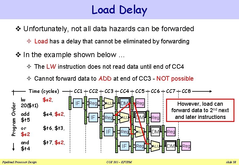
Load Delay v Unfortunately, not all data hazards can be forwarded ² Load has a delay that cannot be eliminated by forwarding v In the example shown below … ² The LW instruction does not read data until end of CC 4 ² Cannot forward data to ADD at end of CC 3 - NOT possible Program Order Time (cycles) lw $s 2, 20($t 1) add $t 5 $s 4, $s 2, or $s 2 $t 6, $t 3, and $t 4 $t 7, $s 2, Pipelined Processor Design CC 1 CC 2 CC 3 CC 4 CC 5 IF Reg ALU DM Reg IF Reg ALU DM COE 301 – KFUPM CC 6 CC 7 CC 8 However, load can forward data to 2 nd next and later instructions Reg slide 38
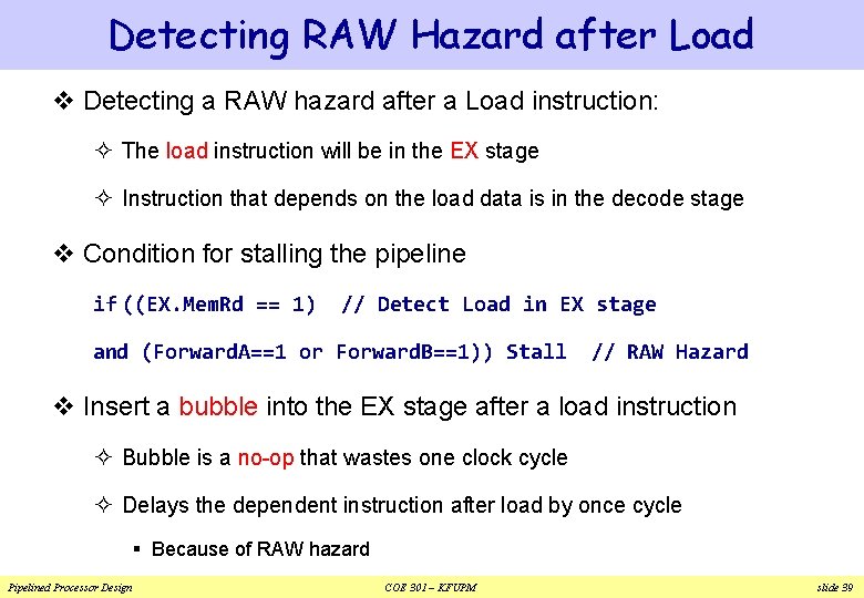
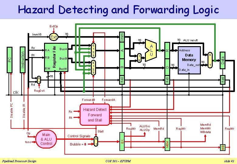
Detecting RAW Hazard after Load v Detecting a RAW hazard after a Load instruction: ² The load instruction will be in the EX stage ² Instruction that depends on the load data is in the decode stage v Condition for stalling the pipeline if ((EX. Mem. Rd == 1) // Detect Load in EX stage and (Forward. A==1 or Forward. B==1)) Stall // RAW Hazard v Insert a bubble into the EX stage after a load instruction ² Bubble is a no-op that wastes one clock cycle ² Delays the dependent instruction after load by once cycle § Because of RAW hazard Pipelined Processor Design COE 301 – KFUPM slide 39
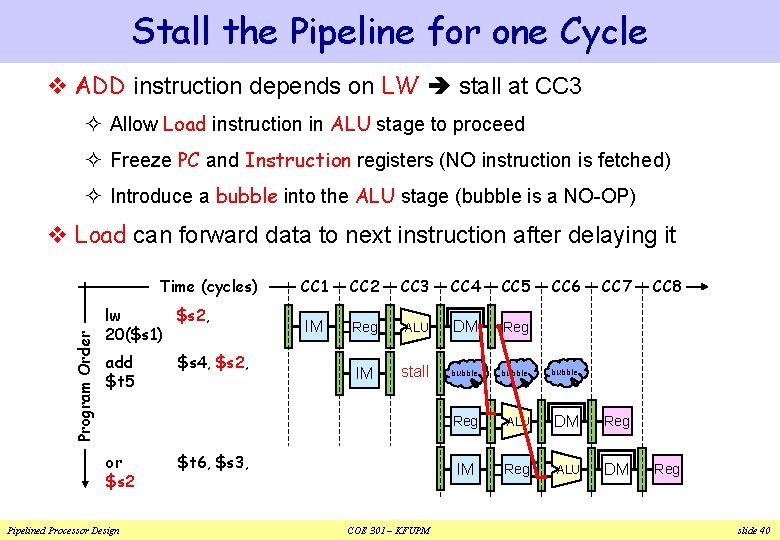
Stall the Pipeline for one Cycle v ADD instruction depends on LW stall at CC 3 ² Allow Load instruction in ALU stage to proceed ² Freeze PC and Instruction registers (NO instruction is fetched) ² Introduce a bubble into the ALU stage (bubble is a NO-OP) v Load can forward data to next instruction after delaying it Program Order Time (cycles) lw $s 2, 20($s 1) add $t 5 or $s 2 Pipelined Processor Design $s 4, $s 2, CC 1 CC 2 CC 3 CC 4 CC 5 IM Reg ALU DM Reg IM stall bubble Reg ALU DM Reg IM Reg ALU DM $t 6, $s 3, COE 301 – KFUPM CC 6 CC 7 CC 8 Reg slide 40
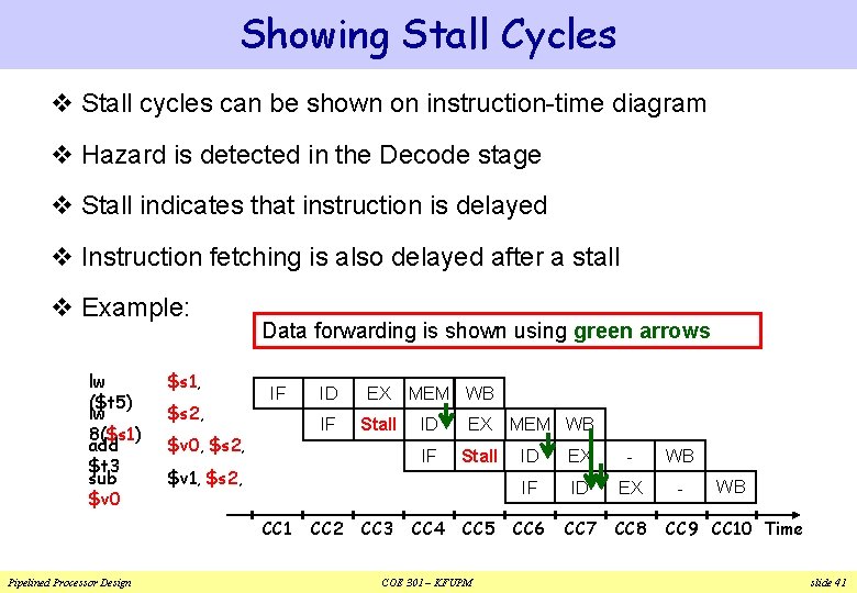
Showing Stall Cycles v Stall cycles can be shown on instruction-time diagram v Hazard is detected in the Decode stage v Stall indicates that instruction is delayed v Instruction fetching is also delayed after a stall v Example: lw ($t 5) lw 8($s 1) add $t 3 sub $v 0 $s 1, $s 2, Data forwarding is shown using green arrows IF $v 0, $s 2, EX IF Stall $v 1, $s 2, CC 1 Pipelined Processor Design ID CC 2 CC 3 MEM WB ID EX IF Stall CC 4 CC 5 COE 301 – KFUPM MEM WB ID EX - WB IF ID EX - CC 6 CC 7 CC 8 WB CC 9 CC 10 Time slide 41
Hazard Detecting and Forwarding Logic Ext. Op RW Rd 1 Data_out R 32 0 32 1 Data_in Reg. Dst Rt Op func Pipelined Processor Design Main & ALU Control Hazard Detect Forward and Stall Reg. Wr Stall Control Signals Bubble = 0 0 1 COE 301 – KFUPM ALUSrc ALUOp Mem. Rd Reg. Wr Mem. Rd Mem. Wr WBdata Reg. Wr WB Rs Forward. A MEM Disable IR Forward. B EX clk Disable PC 32 Rd 2 32 0 1 Data Memory 0 0 1 2 3 Bus. W Address Data Imm Bus. B ALU result Rd 4 RB A L U D Rt 0 1 2 3 Bus. A 32 32 Rd 3 RA 32 A Register File PC Instruction Rs Ext B Imm 16 slide 42
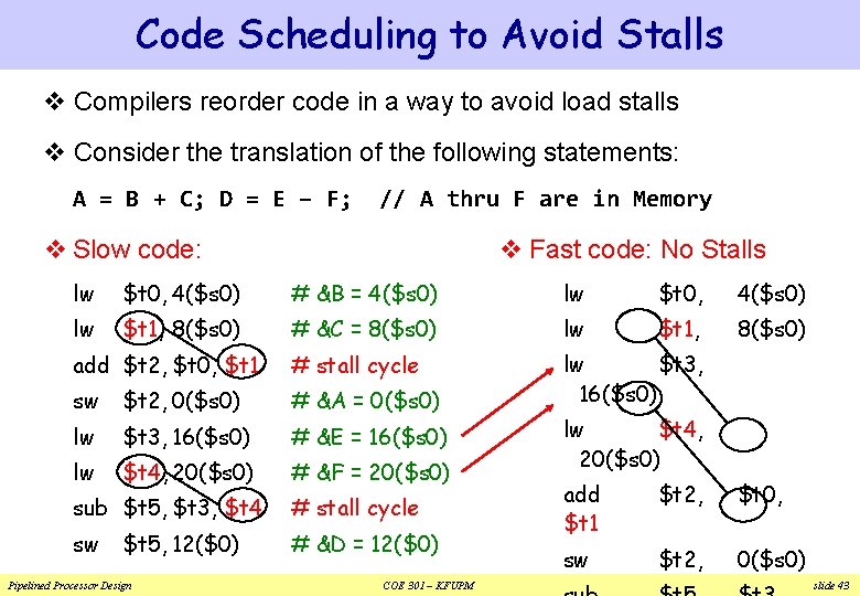
Code Scheduling to Avoid Stalls v Compilers reorder code in a way to avoid load stalls v Consider the translation of the following statements: A = B + C; D = E – F; // A thru F are in Memory v Fast code: No Stalls v Slow code: lw $t 0, 4($s 0) # &B = 4($s 0) lw $t 0, 4($s 0) lw $t 1, 8($s 0) # &C = 8($s 0) lw $t 1, 8($s 0) add $t 2, $t 0, $t 1 # stall cycle sw $t 2, 0($s 0) # &A = 0($s 0) lw $t 3, 16($s 0) # &E = 16($s 0) lw $t 4, 20($s 0) # &F = 20($s 0) sub $t 5, $t 3, $t 4 # stall cycle sw # &D = 12($0) $t 5, 12($0) Pipelined Processor Design COE 301 – KFUPM lw $t 4, 20($s 0) add $t 1 $t 2, $t 0, sw $t 2, 0($s 0) slide 43
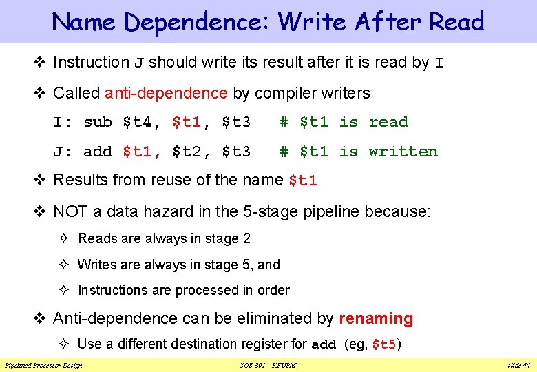
Name Dependence: Write After Read v Instruction J should write its result after it is read by I v Called anti-dependence by compiler writers I: sub $t 4, $t 1, $t 3 # $t 1 is read J: add $t 1, $t 2, $t 3 # $t 1 is written v Results from reuse of the name $t 1 v NOT a data hazard in the 5 -stage pipeline because: ² Reads are always in stage 2 ² Writes are always in stage 5, and ² Instructions are processed in order v Anti-dependence can be eliminated by renaming ² Use a different destination register for add (eg, $t 5) Pipelined Processor Design COE 301 – KFUPM slide 44
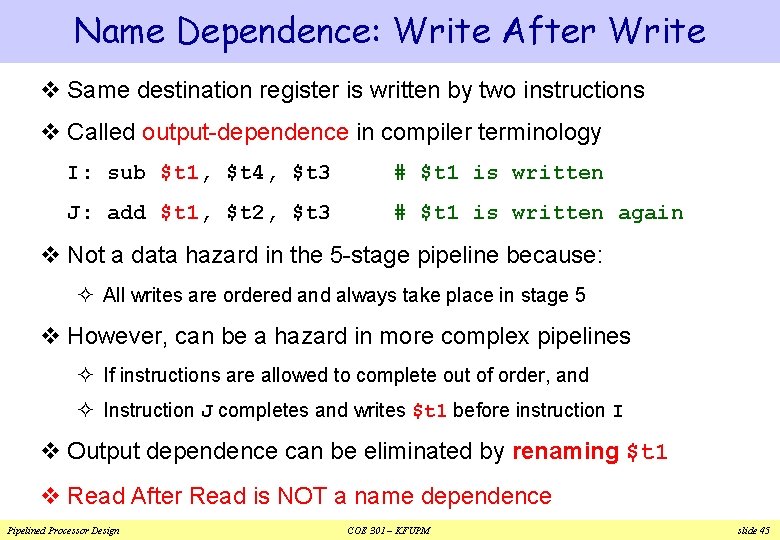
Name Dependence: Write After Write v Same destination register is written by two instructions v Called output-dependence in compiler terminology I: sub $t 1, $t 4, $t 3 # $t 1 is written J: add $t 1, $t 2, $t 3 # $t 1 is written again v Not a data hazard in the 5 -stage pipeline because: ² All writes are ordered and always take place in stage 5 v However, can be a hazard in more complex pipelines ² If instructions are allowed to complete out of order, and ² Instruction J completes and writes $t 1 before instruction I v Output dependence can be eliminated by renaming $t 1 v Read After Read is NOT a name dependence Pipelined Processor Design COE 301 – KFUPM slide 45
Next. . . v Pipelining versus Serial Execution v Pipelined Datapath and Control v Pipeline Hazards v Data Hazards and Forwarding v Load Delay, Hazard Detection, and Stall v Control Hazards v Delayed Branch and Dynamic Branch Prediction Pipelined Processor Design COE 301 – KFUPM slide 46
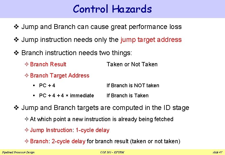
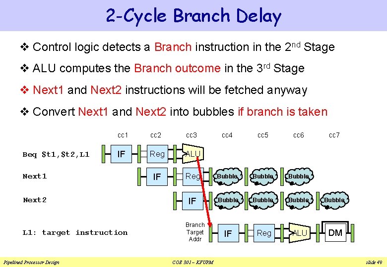
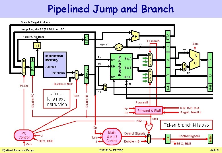
Control Hazards v Jump and Branch can cause great performance loss v Jump instruction needs only the jump target address v Branch instruction needs two things: ² Branch Result Taken or Not Taken ² Branch Target Address § PC + 4 If Branch is NOT taken § PC + 4 × immediate If Branch is Taken v Jump and Branch targets are computed in the ID stage ² At which point a new instruction is already being fetched ² Jump Instruction: 1 -cycle delay ² Branch: 2 -cycle delay for branch result (taken or not taken) Pipelined Processor Design COE 301 – KFUPM slide 47
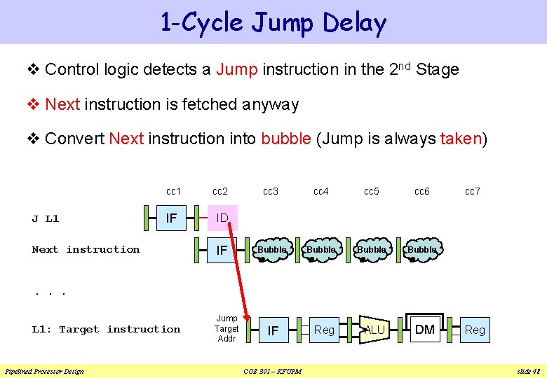
1 -Cycle Jump Delay v Control logic detects a Jump instruction in the 2 nd Stage v Next instruction is fetched anyway v Convert Next instruction into bubble (Jump is always taken) J L 1 cc 2 IF ID Next instruction IF cc 3 cc 4 cc 5 cc 6 Bubble Reg ALU DM cc 7 . . . L 1: Target instruction Pipelined Processor Design Jump Target Addr IF COE 301 – KFUPM Reg slide 48
2 -Cycle Branch Delay v Control logic detects a Branch instruction in the 2 nd Stage v ALU computes the Branch outcome in the 3 rd Stage v Next 1 and Next 2 instructions will be fetched anyway v Convert Next 1 and Next 2 into bubbles if branch is taken Beq $t 1, $t 2, L 1 cc 2 cc 3 IF Reg ALU IF Next 1 Next 2 L 1: target instruction Pipelined Processor Design cc 4 cc 5 cc 6 Reg Bubble Bubble IF Reg ALU DM Branch Target Addr COE 301 – KFUPM cc 7 slide 49
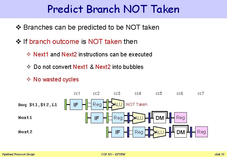
Predict Branch NOT Taken v Branches can be predicted to be NOT taken v If branch outcome is NOT taken then ² Next 1 and Next 2 instructions can be executed ² Do not convert Next 1 & Next 2 into bubbles ² No wasted cycles Beq $t 1, $t 2, L 1 Next 2 Pipelined Processor Design cc 1 cc 2 cc 3 IF Reg ALU NOT Taken IF cc 4 cc 5 cc 6 Reg ALU DM Reg IF Reg ALU DM COE 301 – KFUPM cc 7 Reg slide 50
Pipelined Jump and Branch Target Address Forward. A Rd Kill 1 Rs Zero Pipelined Processor Design BEQ, BNE func J COE 301 – KFUPM Control Signals Bubble = 0 Imm D Reg. Wr, Mem. Rd Stall Taken branch kills two Op Main & ALU Control Rd 2, Rd 3, Rd 4 Forward & Stall Kill 2 J A Forward. B Rt PC Control 32 0 1 Control Signals BEQ, BNE MEM Disable PC Jump kills next instruction 0 0 1 2 3 32 0 1 A L U Rd 3 Bubble = NOP PCSrc 32 1 Bus. B Bus. W Zero Rd 2 1 RW 0 1 2 3 Bus. A EX 2 0 Register File Instruction RB Disable IR 1 RA Rt Address PC 0 Rs Instruction 00 Instruction Memory Ext B Imm 16 +1 32 R + NPC Next PC Address BTA Jump Target = PC[31: 28] ‖ Imm 26 slide 51
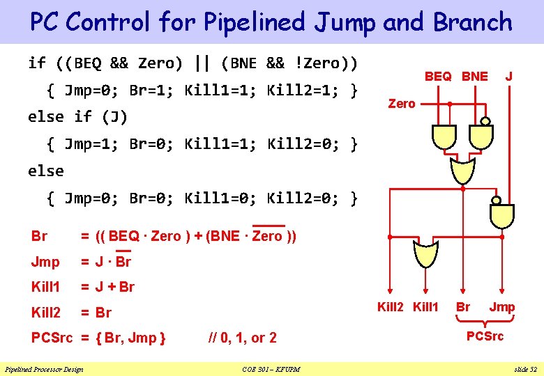
PC Control for Pipelined Jump and Branch if ((BEQ && Zero) || (BNE && !Zero)) { Jmp=0; Br=1; Kill 1=1; Kill 2=1; } else if (J) BEQ BNE J Zero { Jmp=1; Br=0; Kill 1=1; Kill 2=0; } else { Jmp=0; Br=0; Kill 1=0; Kill 2=0; } Br = (( BEQ · Zero ) + (BNE · Zero )) Jmp = J · Br Kill 1 = J + Br Kill 2 = Br PCSrc = { Br, Jmp } Pipelined Processor Design Kill 2 Kill 1 // 0, 1, or 2 COE 301 – KFUPM Br Jmp PCSrc slide 52
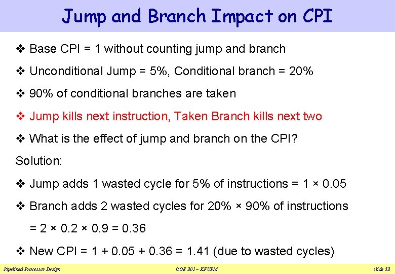
Jump and Branch Impact on CPI v Base CPI = 1 without counting jump and branch v Unconditional Jump = 5%, Conditional branch = 20% v 90% of conditional branches are taken v Jump kills next instruction, Taken Branch kills next two v What is the effect of jump and branch on the CPI? Solution: v Jump adds 1 wasted cycle for 5% of instructions = 1 × 0. 05 v Branch adds 2 wasted cycles for 20% × 90% of instructions = 2 × 0. 9 = 0. 36 v New CPI = 1 + 0. 05 + 0. 36 = 1. 41 (due to wasted cycles) Pipelined Processor Design COE 301 – KFUPM slide 53
Next. . . v Pipelining versus Serial Execution v Pipelined Datapath and Control v Pipeline Hazards v Data Hazards and Forwarding v Load Delay, Hazard Detection, and Stall v Control Hazards v Delayed Branch and Dynamic Branch Prediction Pipelined Processor Design COE 301 – KFUPM slide 54
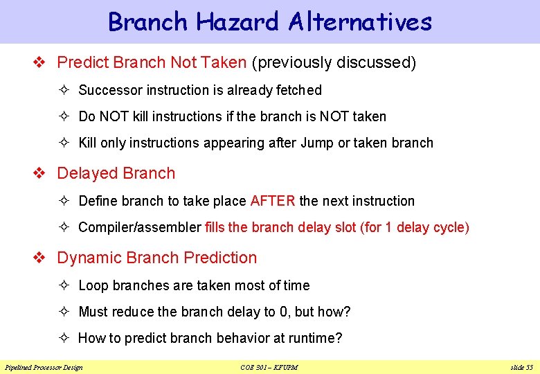
Branch Hazard Alternatives v Predict Branch Not Taken (previously discussed) ² Successor instruction is already fetched ² Do NOT kill instructions if the branch is NOT taken ² Kill only instructions appearing after Jump or taken branch v Delayed Branch ² Define branch to take place AFTER the next instruction ² Compiler/assembler fills the branch delay slot (for 1 delay cycle) v Dynamic Branch Prediction ² Loop branches are taken most of time ² Must reduce the branch delay to 0, but how? ² How to predict branch behavior at runtime? Pipelined Processor Design COE 301 – KFUPM slide 55
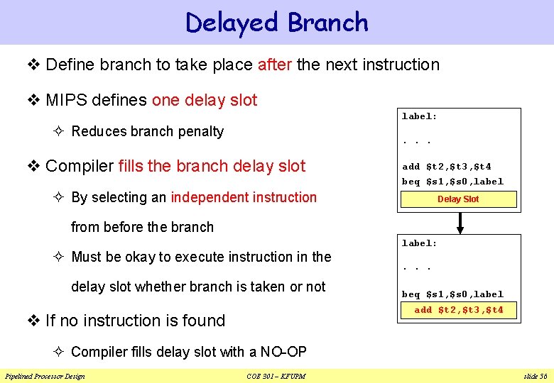
Delayed Branch v Define branch to take place after the next instruction v MIPS defines one delay slot label: ² Reduces branch penalty . . . v Compiler fills the branch delay slot add $t 2, $t 3, $t 4 beq $s 1, $s 0, label ² By selecting an independent instruction Delay Slot from before the branch ² Must be okay to execute instruction in the delay slot whether branch is taken or not label: . . . beq $s 1, $s 0, label add $t 2, $t 3, $t 4 v If no instruction is found ² Compiler fills delay slot with a NO-OP Pipelined Processor Design COE 301 – KFUPM slide 56
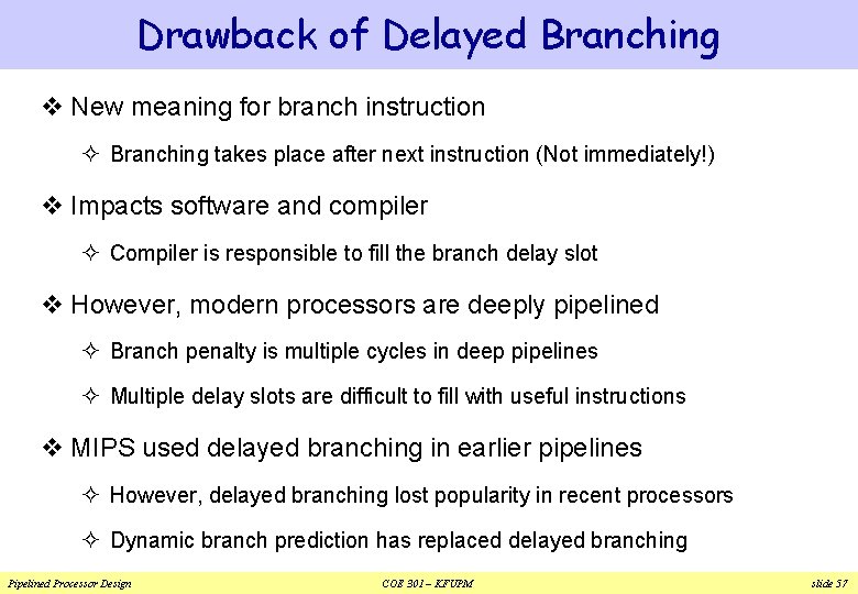
Drawback of Delayed Branching v New meaning for branch instruction ² Branching takes place after next instruction (Not immediately!) v Impacts software and compiler ² Compiler is responsible to fill the branch delay slot v However, modern processors are deeply pipelined ² Branch penalty is multiple cycles in deep pipelines ² Multiple delay slots are difficult to fill with useful instructions v MIPS used delayed branching in earlier pipelines ² However, delayed branching lost popularity in recent processors ² Dynamic branch prediction has replaced delayed branching Pipelined Processor Design COE 301 – KFUPM slide 57
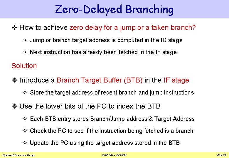
Zero-Delayed Branching v How to achieve zero delay for a jump or a taken branch? ² Jump or branch target address is computed in the ID stage ² Next instruction has already been fetched in the IF stage Solution v Introduce a Branch Target Buffer (BTB) in the IF stage ² Store the target address of recent branch and jump instructions v Use the lower bits of the PC to index the BTB ² Each BTB entry stores Branch/Jump address & Target Address ² Check the PC to see if the instruction being fetched is a branch ² Update the PC using the target address stored in the BTB Pipelined Processor Design COE 301 – KFUPM slide 58
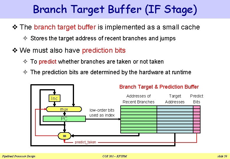
Branch Target Buffer (IF Stage) v The branch target buffer is implemented as a small cache ² Stores the target address of recent branches and jumps v We must also have prediction bits ² To predict whether branches are taken or not taken ² The prediction bits are determined by the hardware at runtime Branch Target & Prediction Buffer Addresses of Recent Branches Inc mux PC Target Addresses Predict Bits low-order bits used as index = predict_taken Pipelined Processor Design COE 301 – KFUPM slide 59
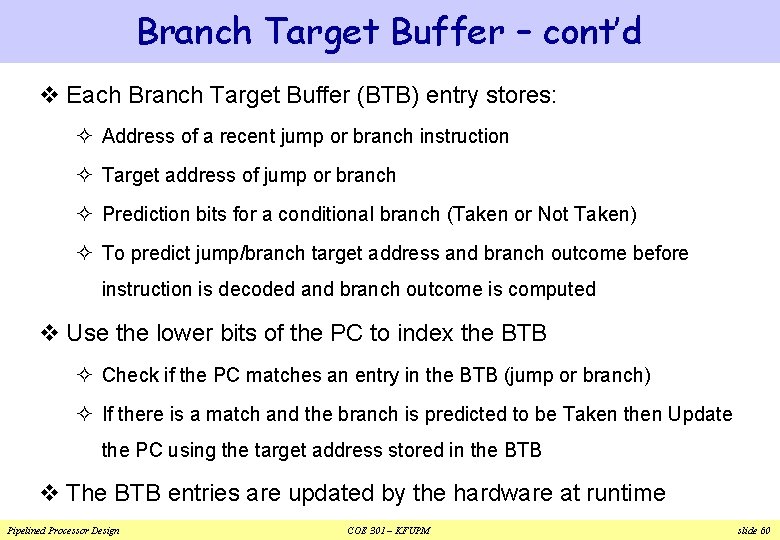
Branch Target Buffer – cont’d v Each Branch Target Buffer (BTB) entry stores: ² Address of a recent jump or branch instruction ² Target address of jump or branch ² Prediction bits for a conditional branch (Taken or Not Taken) ² To predict jump/branch target address and branch outcome before instruction is decoded and branch outcome is computed v Use the lower bits of the PC to index the BTB ² Check if the PC matches an entry in the BTB (jump or branch) ² If there is a match and the branch is predicted to be Taken then Update the PC using the target address stored in the BTB v The BTB entries are updated by the hardware at runtime Pipelined Processor Design COE 301 – KFUPM slide 60
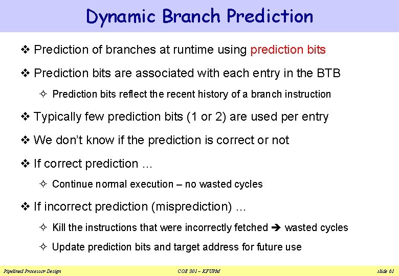
Dynamic Branch Prediction v Prediction of branches at runtime using prediction bits v Prediction bits are associated with each entry in the BTB ² Prediction bits reflect the recent history of a branch instruction v Typically few prediction bits (1 or 2) are used per entry v We don’t know if the prediction is correct or not v If correct prediction … ² Continue normal execution – no wasted cycles v If incorrect prediction (misprediction) … ² Kill the instructions that were incorrectly fetched wasted cycles ² Update prediction bits and target address for future use Pipelined Processor Design COE 301 – KFUPM slide 61
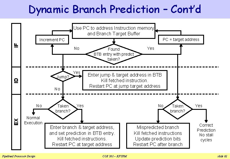
Dynamic Branch Prediction – Cont’d Use PC to address Instruction memory and Branch Target Buffer PC = target address IF Increment PC No ID Jump? Yes No EX No Normal Execution Pipelined Processor Design Taken branch? Found BTB entry with predict taken? Yes Enter jump & target address in BTB Kill fetched instruction. Restart PC at jump target address Yes No Enter branch & target address, and set prediction in BTB entry. Kill fetched instructions. Restart PC at target address COE 301 – KFUPM Taken branch? Mispredicted branch Kill fetched instructions Update prediction bits Restart PC after branch Yes Correct Prediction No stall cycles slide 62
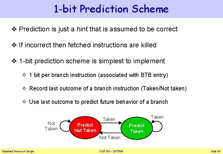
1 -bit Prediction Scheme v Prediction is just a hint that is assumed to be correct v If incorrect then fetched instructions are killed v 1 -bit prediction scheme is simplest to implement ² 1 bit per branch instruction (associated with BTB entry) ² Record last outcome of a branch instruction (Taken/Not taken) ² Use last outcome to predict future behavior of a branch Not Taken Predict Not Taken Predict Taken Not Taken Pipelined Processor Design COE 301 – KFUPM slide 63
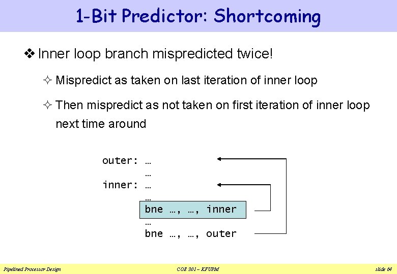
1 -Bit Predictor: Shortcoming v Inner loop branch mispredicted twice! ² Mispredict as taken on last iteration of inner loop ² Then mispredict as not taken on first iteration of inner loop next time around outer: … … inner: … … bne …, …, inner … bne …, …, outer Pipelined Processor Design COE 301 – KFUPM slide 64
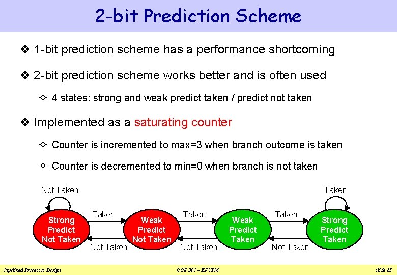
2 -bit Prediction Scheme v 1 -bit prediction scheme has a performance shortcoming v 2 -bit prediction scheme works better and is often used ² 4 states: strong and weak predict taken / predict not taken v Implemented as a saturating counter ² Counter is incremented to max=3 when branch outcome is taken ² Counter is decremented to min=0 when branch is not taken Taken Not Taken Strong Predict Not Taken Pipelined Processor Design Taken Not Taken Weak Predict Not Taken COE 301 – KFUPM Weak Predict Taken Not Taken Strong Predict Taken slide 65
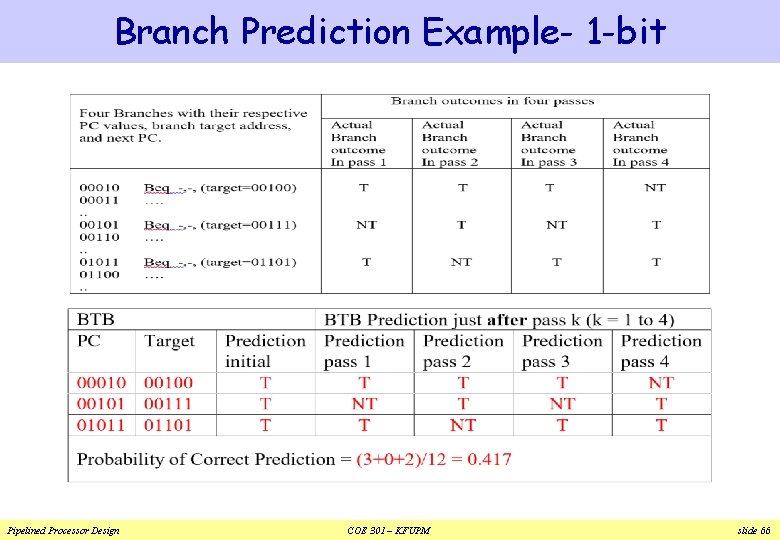
Branch Prediction Example- 1 -bit Pipelined Processor Design COE 301 – KFUPM slide 66
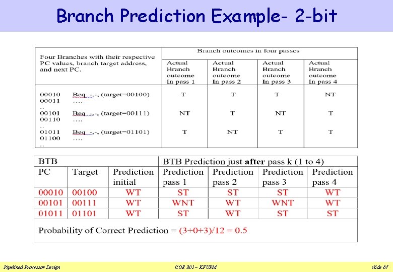
Branch Prediction Example- 2 -bit Pipelined Processor Design COE 301 – KFUPM slide 67
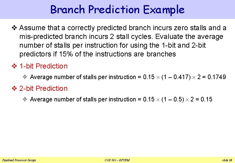
Branch Prediction Example v Assume that a correctly predicted branch incurs zero stalls and a mis-predicted branch incurs 2 stall cycles. Evaluate the average number of stalls per instruction for using the 1 -bit and 2 -bit predictors if 15% of the instructions are branches v 1 -bit Prediction ² Average number of stalls per instruction = 0. 15 (1 – 0. 417) 2 = 0. 1749 v 2 -bit Prediction ² Average number of stalls per instruction = 0. 15 (1 – 0. 5) 2 = 0. 15 Pipelined Processor Design COE 301 – KFUPM slide 68
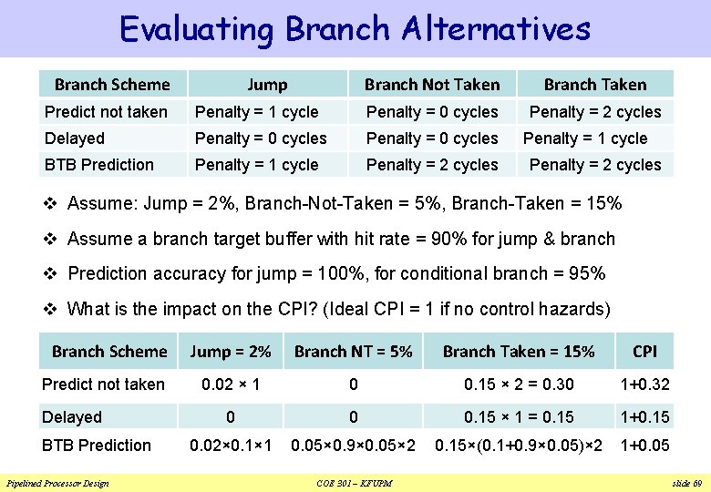
Evaluating Branch Alternatives Branch Scheme Jump Branch Not Taken Branch Taken Penalty = 2 cycles Predict not taken Penalty = 1 cycle Penalty = 0 cycles Delayed Penalty = 0 cycles BTB Prediction Penalty = 1 cycle Penalty = 2 cycles v Assume: Jump = 2%, Branch-Not-Taken = 5%, Branch-Taken = 15% v Assume a branch target buffer with hit rate = 90% for jump & branch v Prediction accuracy for jump = 100%, for conditional branch = 95% v What is the impact on the CPI? (Ideal CPI = 1 if no control hazards) Branch Scheme Predict not taken Delayed BTB Prediction Pipelined Processor Design Jump = 2% Branch NT = 5% Branch Taken = 15% CPI 0. 02 × 1 0 0. 15 × 2 = 0. 30 1+0. 32 0 0 0. 15 × 1 = 0. 15 1+0. 15 0. 02× 0. 1× 1 0. 05× 0. 9× 0. 05× 2 0. 15×(0. 1+0. 9× 0. 05)× 2 1+0. 05 COE 301 – KFUPM slide 69
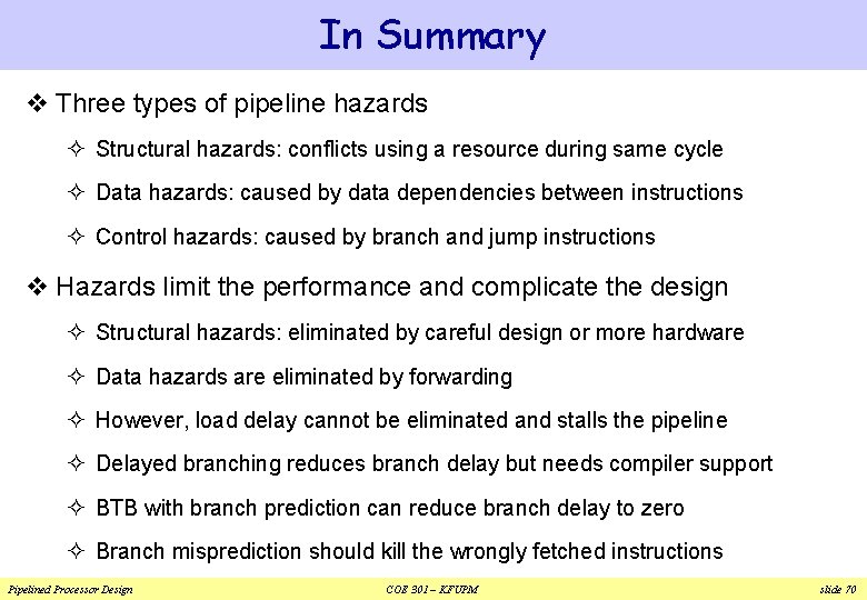
In Summary v Three types of pipeline hazards ² Structural hazards: conflicts using a resource during same cycle ² Data hazards: caused by data dependencies between instructions ² Control hazards: caused by branch and jump instructions v Hazards limit the performance and complicate the design ² Structural hazards: eliminated by careful design or more hardware ² Data hazards are eliminated by forwarding ² However, load delay cannot be eliminated and stalls the pipeline ² Delayed branching reduces branch delay but needs compiler support ² BTB with branch prediction can reduce branch delay to zero ² Branch misprediction should kill the wrongly fetched instructions Pipelined Processor Design COE 301 – KFUPM slide 70