Motorola ACE 3600 Solutions Product Introduction Highlights 1


- Slides: 43

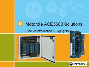
Motorola ACE 3600 Solutions Product Introduction & Highlights 1

ACE 3600 RTU - Building Blocks Power Supply Housing & Chassis CPU Frames I/O Modules Radios Software 2

Key Upgrades § Operating Temperature § Power supply versatility § CPU Operating Speed § Analog Ports resolution § STS Programming Tool § Expanded comm. Ports § Comm. Port Versatility § New Technology 3

Structure and Construction § The ACE 3600 is available in various structures: § Frames that hold various number of modules § On a Metal Chassis that holds the frame, radio (s) and backup battery § In a Housing that holds the frame, modules, radio(s) and backup battery Frame 4 On Metal Chassis In Housing

Frames § The ACE 3600 frames have the following tasks: § To hold the Power-Supply, CPU and I/O modules § To connect the modules with operating voltages § To connect the modules to the CPU No I/O 3 I/O § All frames can be installed on a wall § The 8 I/O Frame can also be installed on a 19” rack § The following frames are available: § § § No I/O frame – Power Supply and CPU only 3 I/O slot frame - Power Supply and CPU and 3 I/O slots 5 I/O slot frame - Power Supply and CPU and 5 I/O slots 7 I/O slot frame - Power Supply and CPU and 7 I/O slots 8 I/O slot frame - Power Supply and CPU and 8 I/O slots PS & CPU Slots 5 I/O 7 I/O Slots Motherboard Metal Base 5 8 I/O

8 I/O Slots Frame - 19” Rack 6

Metal Chassis § ACE 3600 frames can be ordered with small or large Metal Chassis as an option. For 19” rack installation a 19” Metal Chassis is available. § The Metal Chassis enables installation of radio(s), backup battery and other accessories. It can be installed on a wall or in a cabinet. Small Chassis Up to 3 I/O slots 7 Large Chassis Up to 7 I/O slots 19” Chassis

Housing § ACE 3600 can be ordered with small or large NEMA 4 (IP 66) metal housing for outdoor installation. § The housing includes a metal chassis that enables installation of radio, backup battery and other accessories. The housing can be installed on a wall. Small Housing Up to 3 I/O slots 8 Large Housing Up to 7 I/O slots

ACE 3600 CPU Module § Two types of CPU modules are available: § CPU 3610 and CPU 3640 (enhanced Comm. ) § The CPU’s firmware is based on Wind River’s VXWorks Real-time Operating System. § It controls the I/O modules, processes the gathered data and communicates with the outside world. § The module’s processor is Power Quick II MPC 8270, 32 bit § It has extended communication capabilities, § Built in DMA and floating point calculation support. § The module core is based on Field Programmable Gate Array (FPGA). § The module includes: § on-board memory, communication ports, I/O bus interface and other circuits. 9

CPU Module Description Status LEDs Communication Ports LEDs Pushbutton 1/2 Plug-In 1 Port (option) Serial 1 Port (RS-232/RS 485) Serial 2 Port (RS-232) Ethernet 1 Port (on CPU 3640 only) Plug-In 2 Port (option) User LEDs 10

CPU Memory § The ACE 3600 CPU includes § On board FLASH and SDRAM memory • FLASH: 16 MB Total / 3 MB free for user application & data. • SDRAM: 32 MB SDRAM Total / 10 MB for user application & data. § Optional SRAM Plug-in memory. • 4 MB Total / all for user data (available in Dec/07) § The FLASH stores the: § Firmware, configurations files, user program files, and the user data files. § The SDRAM stores § Firmware run data and user program temporary data. § Optional SRAM memory expansion § Used for logging user data. § The SRAM data is retained using an on-board rechargeable lithium battery 11

CPU Communication Ports § Includes several communication ports: § On Board ports: § Serial 1 (SI 1) – RS-232 / RS 485 serial port (configurable) § Serial 2 (SI 2) – RS-232 serial port § Ethernet 1 (E 1) - 10/100 Mb Ethernet port (CPU 3640 only) § Plug-in Ports bays (options), for different types of ports: § Plug-in 1 (PI 1) – fits RS-232, RS 485, 10 MB Ethernet, 10/100 Mb Ethernet, or Radio Plug-in option § Plug-in 2 (PI 2) – fits RS-232, RS 485, 10 MB Ethernet, or Radio Plug-in port option. 12

CPU Plug-in Port Options § Serial Ports § RS 232 up to 230 kb/s § RS 485 up to 460 kb/s § Configurable conventional/ Trunk radio modems: § DPSK 1. 2 kb/s, FSK 2. 4 kb/s , DFM 4. 8 kb/s , Duo-Binary 9. 6 kb/s § Ethernet § 10/100 Mb/s (In Plug-in 1 only) § Ethernet 10 Mb/s 13

Communication Media Options § Motorola Radio Support: § Mobile two-way radio - CM 200, CM 140, EM 200, GM 3188, CDM 750 § Portable two way radio - HT 750, GP 328, PRO 5150 § Astro – XTL 5000 (cancelled) & XTL 2500 (mobile digital and analog trunking), XTS 2500 (portable digital Trunking) § Dimetra – MTM 700/800 § 3 rd party Radio / MODEM connectivity: (VAR integration and support - your mileage may vary!) § 3 rd party two way radios / older Motorola Series (MCS 2000) § Data radios (MDS, Data radio, etc. ) § Dial-up modems § Cellular modems (dial mode & PD, GPRS, CDMA) § Broadband (WLAN, Canopy, i. Net 900, etc. ) 14

Power Supply § The ACE 3600 power supply modules provide the CPU and I/O modules with their operating voltages via the motherboard bus. § It also provides power to radios, modems and accessories. § The available power supply models are: § DC Power Supply 10. 8 -15. 5 V (Default) § DC Power Supply 10. 8 -15. 5 V Low-Tier § DC Power Supply 18 -72 V (floating) § DC PS 18 -72 V (floating) with Battery Charger § AC Power Supply 90 -264 V with Battery Charger 15

Power Supply Description Future 16 1/2

Low-Tier Power Supply Description Auxiliary Output 1 A Auxiliary Output 1 B DC Power Input 17

Power Supply Characteristics § Protected On/Off switch on the front panel*. § Controlled auxiliary voltage outputs*. § Heat convection cooling § Short protection in outputs. § Over heating protection. § The PS is monitored by the CPU module. § Status LEDs in the front panel*. § The PS is located on the leftmost slot on the frame. § Controlled power line enables centralized inhibiting of relay outputs in selectable DO modules*. * Except for Low-Tier PS 18

Battery Charger Characteristics § Support 6. 5 or 10 Ah lead-acid backup battery. § Automatically switches to the backup battery when the main AC or DC power source fails. § Automatic switchover to main power on power return. § Optimized temperature compensated charging. § Overcharging protection. § Over-discharge protection. § Performs battery test with battery controlled discharge cycle. 19

Power and Ground Connections § The power connection to all the ACE 3600 Power Supply types is via the power junction box located on the frame beneath the Power Supply slot. § The power junction box is connected to the Power Supply with a power cable Power Supply Power Junction Box 20 User Power Cable Grounding Strip Cable Anchor

I/O Modules § The ACE 3600 offers various I/O modules types: § Digital Input § Digital Output § Analog Input § Analog Output § Mixed I/O § The I/O modules have the following common characteristics: § Enlarged I/O capacity per module § I/O Isolation and protection § Module hot swap capability § Automatic module recognition (by the CPU for config. upload) § Indication LED per each I/O + module error LED § 20 and 40 Pin Terminal Block (TB) connectors (3. 81 mm / 18 AWG) § TB connector holder with protection key § Cables (based on TB Holder) 21

I/O Module Description Module Door Motherboard Connector LEDs Terminal Block Connector 20 Pin Module 22 40 Pin Module

Digital Input (DI) Modules § 16 DI/ 32 DI Modules § 16 DI Fast 24 V module § 32 DI Fast 24 V module § 16 DI Fast 24 V IEC 61131 -2 Type II module § 32 DI Fast 24 V IEC 61131 -2 Type II module NOT RECOMMENDED FOR MOST IRRIGATION USES 23

DI Characteristics 1/2 § Each Input has a dedicated status LED. § Optical isolation § All inputs are optically isolated and surge protected. § Fast capture § Each inputs can be configured as Fast Capture inputs. § 16 and 32 DI Fast 24 V modules can be configured as AC inputs. § Multiple inputs act as Fast Counter Inputs (20 in 32 DI, all in 16 DI). 24

DI Characteristics 2/2 § Filtering § DC inputs filter – configurable up to 50. 8 ms. § Fast Counter input filter - configurable up to 12. 75 ms. § The filter setup can be changed during run-time by the user program. § Fast Event § All inputs can be fast triggers to a high priority user process (Fast Event). § Other Characteristics § In case of module failure, each input can be set to show to the user program a predefined value (1 or 0) or to show the last value. § Each input can be “masked” to show to the user program a predefined value constantly (ignoring the real input value). 25

Digital Output (DO) Relay Modules – RECOMMENDED DO MODULE FOR IRRIGATION! § ACE 3600 offers 8 DO and 16 DO Relay modules § The modules available are: § 8 DO Electrically Energized (EE) Relay module § 16 DO Electrically Energized (EE) Relay module § 8 DO Magnetically Latched (ML) Relay module § 16 DO Magnetically Latched (ML) Relay module 26

DO Relay Characteristics 1/2 § Output Arrangement: § 8 DO - 3 X Form C (SPDT) and 5 X Form A (SPST) § 16 DO - 6 X Form C (SPDT) and 10 X Form A (SPST) § Contact voltage ratings: § Max. 60 V DC or 30 V AC RMS (42. 4 V peak). § Contact Power Ratings: § 2 A @ 30 V DC, 0. 6 A @ 60 V DC or 0. 6 A @ 30 V AC (resistive load) § Each relay has a dedicated status LED. 27

DO Relay Characteristics 2/2 § Each output has actual relay position backindication available to the user program. § Output can be controlled by high priority process (Fast Event). § In case of CPU fail, each output can be set to a predefined value (1 or 0) or to stay in its last value. § Each output can be “masked” to stay constantly in a predefined value (ignoring the user program command). § All relays are central disable / enable § Selectable per module § Controlled from the power supply panel. 28

Analog Input (AI) Modules § ACE 3600 offers 8 AI and 16 AI modules. § The modules available are: § 8 AI ± 20 m. A (4 -20 m. A) module § 16 AI ± 20 m. A (4 -20 m. A) module § 8 AI ± 5 V (0 -5 V, 1 -5 V) module § 16 AI ± 5 V (0 -5 V, 1 -5 V) module 29

AI Modules Characteristics 1/2 § 16 bit A/D (including sign) § Accuracy ± 0. 1% of full scale § Compare to only 12 -bit resolution on MOSCAD § Input Impedance § ± 20 m. A input : < 250 Ω, ± 5 V input : > 1 MΩ § Programmable 50 or 60 Hz filtering § Input Scan time 10 ms @ 50 Hz filtering, 8. 33 ms @ 60 Hz filtering § Selectable smoothing (input filtering): 2, 4, 8, 16, 32, 64 or 128 samples 30

AI Modules Characteristics 2/2 § Automatic Input Calibration § Individual input Scaling § Other Characteristics § In case of module failure, each input can be set to show to the user program a predefined value or to show the last value. § Each input can be “masked” to show to the user program a predefined value constantly (ignoring the user program input value). § Overflow and Underflow levels can be configured to: § Current inputs: ± 20 m. A or 4 -20 m. A § Voltage Inputs: ± 5 V, 0 -5 V, or 1 -5 V 31

Analog Output (AO) Module § 4 AO Module § Each AO channel can be used as: § 0 to 20 m. A (4 -20 m. A) channel, or § 0 to 10 V DC channel § Internal isolated power source for the AO channels 32

AO Module Characteristics § 14 bit D/A § Accuracy ± 0. 1% of full scale @25 °C § Output Load § Voltage: > 1. 0 kΩ, < 1. 0 µf § Current: < 750 Ω (internal power source) § Temperature Stability § Minimum ± 30 PPM/°C § Internal Channel Settling Time § Max. 1 ms 33 1/2

AO Module Characteristics 2/2 § Factory and User Output Calibration § Individual Output Scaling § Supports AO handling of Legacy MOSCAD & MOSCAD-L applications program (12 bit). § Other Characteristics § In case of CPU fail, each output can be set to a predefined value or to stay in its last value. § Each output can be “masked” to stay constantly in a predefined value (ignoring the user program command). 34

Mixed Analog Modules § The modules available are: § 4 AO + 8 AI ± 20 m. A § 4 AO + 8 AI ± 5 V § Each AO channel in both modules provides: § 0 to 20 m. A (4 -20 m. A) channel, or § 0 to 10 V DC channel § Supports AO handling of Legacy MOSCAD & MOSCAD-L applications program (12 bit). § AI channels have the same characteristics as in the 8 AI and 16 AI modules 35

DO / DI Modules – RECOMMENDED DI MODULE FOR IRRIGATION USE!!! § The modules available are: § 16 DO/DI module § 32 DO/DI module § Each module has groups of 8 MOSFET outputs § Each group can be configured to operate as 8 dry contact inputs. 32 DO/DI configurations 36

DO/DI Module Characteristics 1/2 § Outputs § Up to 500 m. A per output (current sink) § Dedicated status LED. § Back-indication showing the actual output state (available to the user program). § Output can be controlled by high priority process (Fast Event). § All outputs central disable / enable - Selectable per module, controlled from the power supply panel. 37

DO/DI Module Characteristics 2/2 § Inputs § 16/20 Inputs can be used as Counter Inputs (up to 1 KHz). § Dedicated status LED. § In case of CPU fail, each output can be set to a predefined value (1 or 0) or to stay in its last value. § Each output can be “masked” to stay constantly in a predefined value (ignoring the user program command). § All inputs can be fast triggers to a high priority user process (Fast Event). § Inputs filter – configurable up to 50. 8 ms. 38

Mixed I/O Modules The modules available are: § 16 DI / 4 DO EE / 4 AI : § 16 Digital Inputs – Fast 24 V IEC 61131 Type II § 4 Digital Outputs – Electrically Energized (EE) Relay § 4 Analog Inputs - ± 20 m. A (4 -20 m. A) § 16 DI / 4 DO ML / 4 AI : § 16 Digital Inputs – Fast 24 V IEC 61131 Type II § 4 Digital Outputs – Magnetically Latched (ML) Relay § 4 Analog Inputs - ± 20 m. A (4 -20 m. A) § I/O characteristics are equivalent to DI, DO and AI modules. 39

I/O Module Terminal Block (TB) Holder § Structure § The holder secures the I/O connections and TBs neatly in place and forms a single connector plug per module. § The TB cable wires are concealed and each TB can be labeled. § Key coding mechanism § Provided to prevent cabling errors (TB in wrong module) § The coding mechanism has a number of combinations that exceeds the maximum number of I/O slots on a Frame. § Cabling § Three meter cable suitable for I/O module, based on TB Holder. § TB holder kits can be ordered separately (does not include cables). 40

Terminal Block (TB) Holder Description 41

Plug-In 24 V Floating Power Supply § 24 V DC floating output plug-in power supply can be added to certain I/O modules, as detailed in the table below: • 32 DI 2 x PS • 16 DI 1 x PS • 16 AI 1 x PS • 8 AI 1 x PS • Mixed I/O 1 x PS • Mixed Analog 1 x PS § Each plug-in power supply output is controlled by the CPU module. By default, the plug-in power supply is ON and can supply up to 150 m. A. § The power supply plug-in can be turned ON/OFF via the user application program or Hardware Test utility. 42

ACE 3600 Radio Models § The Following radios models are currently available in the ACE 3600 : § Conventional (two-way) models: § Mobile Radio CDM 750 § 136 -174 MHz (including splinter channels), 403 -512 MHz § Portable Radio HT 750, GP 328, PRO 5150 § 136 -174 MHz, 403 -470 MHz § Analog Trunking: § Mobile Radio XTL 2500 in Analog mode § 136 -174 MHz, 403 -470 MHz § Digital Trunking: § Mobile Radio XTL 2500 in Digital mode § Portable Radio XTS 2500 Digital § 136 -174 MHz, 380 -520 MHz, 800 MHz 43
 Ace 3600
 Motorola ace 3600
 Motorola internship
 4225-3600
 3600 ek gösterge tablosu
 Brake power calculation
 3600/23
 Echo bear cat generator
 Usps form 3600-fcm
 110000/3600
 Key highlights icon
 Proposal highlights
 Highlights memorandum
 Investment highlights
 Highlights from the book of isaiah
 Highlights from the book of isaiah
 Work immersion delivery models
 The passage highlights……
 Elements and principles of art
 Unlicensed two-way radios
 What is site trunking
 Radio motorola tunisie
 Canopy wireless broadband
 Motorola radio charger flashing green
 Motorola 68000 block diagram
 Motorola sbv6220 3.0 modem optimum
 Motorola 68000 instruction set
 Caso motorola
 Art sundry motorola
 How to patent a logo
 Motorola microcontroladores
 Motorola 68000 block diagram
 Motorola 68000 assembler
 Xe
Xe Ddns motorola
 Xnzvc assembly
 Mtm 800
 Personal touch computer
 Motorola canopy hack
 Motorola
 Motorola
 Motorola 68000 instruction set
 Motorola power pc
 Motorola ready to go
