
CPU 08 INSTRUCTION SET Motorola CPU 08 Core

- Slides: 34
CPU 08 INSTRUCTION SET Motorola CPU 08 Core Instruction Set MTT 48 3 -42
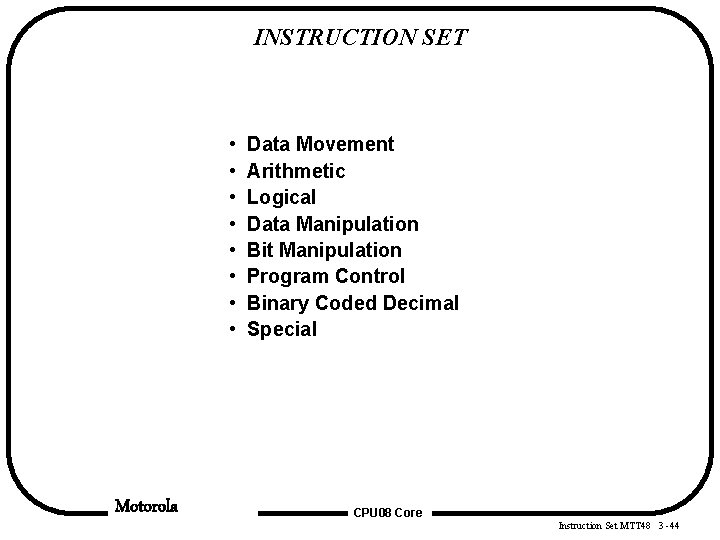
INSTRUCTION SET • • Motorola Data Movement Arithmetic Logical Data Manipulation Bit Manipulation Program Control Binary Coded Decimal Special CPU 08 Core Instruction Set MTT 48 3 -44
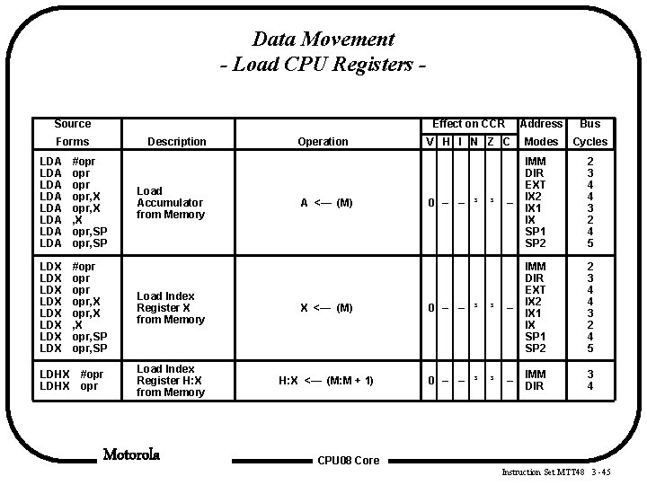
Data Movement - Load CPU Registers Source Forms Description Operation Effect on CCR Address Bus V H I N Z C Modes Cycles 0 – – ³ – IMM DIR EXT IX 2 IX 1 IX SP 1 SP 2 2 3 4 4 3 2 4 5 3 4 LDA LDA #opr opr opr, X , X opr, SP LDX LDX #opr opr opr, X , X opr, SP Load Index Register X from Memory X <— (M) 0 – – ³ ³ – IMM DIR EXT IX 2 IX 1 IX SP 1 SP 2 #opr Load Index Register H: X from Memory H: X <— (M: M + 1) 0 – – ³ ³ – IMM DIR LDHX Load Accumulator from Memory Motorola A <— (M) ³ CPU 08 Core Instruction Set MTT 48 3 -45
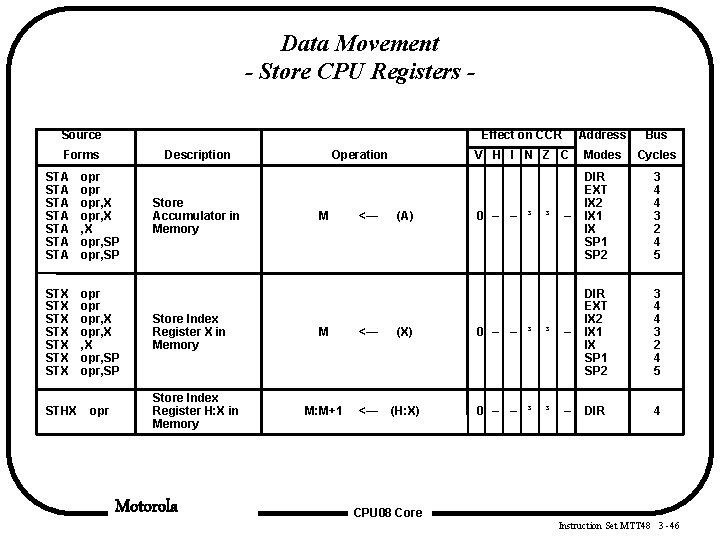
Data Movement - Store CPU Registers Source Forms Description STA STA opr opr, X , X opr, SP STX STX opr opr, X , X opr, SP STHX opr Store Accumulator in Memory Store Index Register X in Memory Store Index Register H: X in Memory Motorola Operation M <— (A) Effect on CCR Address Bus V H I N Z C Modes Cycles 0 – – ³ – DIR EXT IX 2 IX 1 IX SP 1 SP 2 3 4 4 3 2 4 5 4 ³ M <— (X) 0 – – ³ ³ – DIR EXT IX 2 IX 1 IX SP 1 SP 2 M: M+1 <— (H: X) 0 – – ³ ³ – DIR CPU 08 Core Instruction Set MTT 48 3 -46
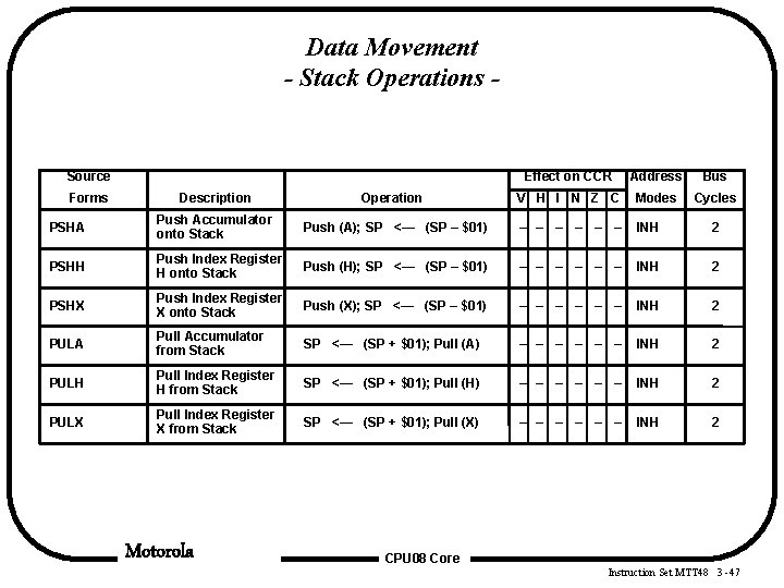
Data Movement - Stack Operations - Source Forms Effect on CCR Address Bus Cycles Description Operation V H I N Z C Modes PSHA Push Accumulator onto Stack Push (A); SP <— (SP – $01) – – – INH 2 PSHH Push Index Register H onto Stack Push (H); SP <— (SP – $01) – – – INH 2 PSHX Push Index Register X onto Stack Push (X); SP <— (SP – $01) – – – INH 2 PULA Pull Accumulator from Stack SP <— (SP + $01); Pull (A) – – – INH 2 PULH Pull Index Register H from Stack SP <— (SP + $01); Pull (H) – – – INH 2 PULX Pull Index Register X from Stack SP <— (SP + $01); Pull (X) – – – INH 2 Motorola CPU 08 Core Instruction Set MTT 48 3 -47
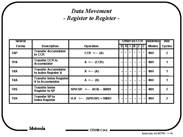
Data Movement - Register to Register - Source Forms Description Effect on CCR Address Bus Operation V H I N Z C Modes Cycles TAP Transfer Accumulator to CCR <— (A) ³ ³ ³ INH 2 TPA Transfer CCR to Accumulator A <— (CCR) – – – INH 1 TAX Transfer Accumulator to Index Register X X <— (A) – – – INH 1 TXA Transfer Index Register X to Accumulator A <— (X) – – – INH 1 TXS Transfer Index Register to SP SPH: SP <— (H: X) – $0001 – – – INH 2 TSX Transfer SP to Index Register H: X <— (SPH: SP) + $0001 – – – INH 2 Motorola ³ ³ ³ CPU 08 Core Instruction Set MTT 48 3 -48
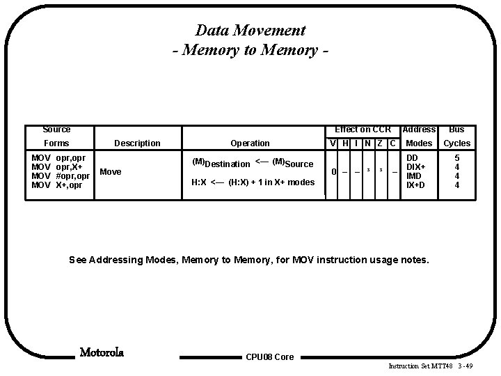
Data Movement - Memory to Memory - Source Forms MOV MOV Description opr, X+ #opr, opr X+, opr Move Operation (M)Destination <— (M)Source H: X <— (H: X) + 1 in X+ modes Effect on CCR Address Bus V H I N Z C Modes Cycles 0 – – ³ DD DIX+ IMD IX+D ³ – 5 4 4 4 See Addressing Modes, Memory to Memory, for MOV instruction usage notes. Motorola CPU 08 Core Instruction Set MTT 48 3 -49
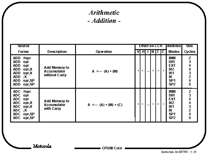
Arithmetic - Addition - Source Forms Description ADD ADD #opr opr opr, X , X opr, SP ADC ADC #opr opr opr, X , X opr, SP Add Memory to Accumulator without Carry Add Memory to Accumulator with Carry Motorola Operation A <— (A) + (M) + (C) Effect on CCR Address Bus V H I N Z C Modes Cycles ³ ³ ³ IMM DIR EXT IX 2 IX 1 IX SP 1 SP 2 2 3 4 4 3 2 4 5 ³ ³ – ³ ³ ³ CPU 08 Core Instruction Set MTT 48 3 -50
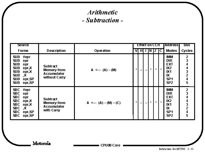
Arithmetic - Subtraction - Source Forms Description SUB SUB #opr opr opr, X , X opr, SP SBC SBC #opr opr opr, X , X opr, SP Subtract Memory from Accumulator without Carry Subtract Memory from Accumulator with Carry Motorola Operation A <— (A) – (M) – (C) Effect on CCR Address Bus V H I N Z C Modes Cycles ³ – – ³ ³ IMM DIR EXT IX 2 IX 1 IX SP 1 SP 2 2 3 4 4 3 2 4 5 ³ – – ³ ³ ³ CPU 08 Core Instruction Set MTT 48 3 -51
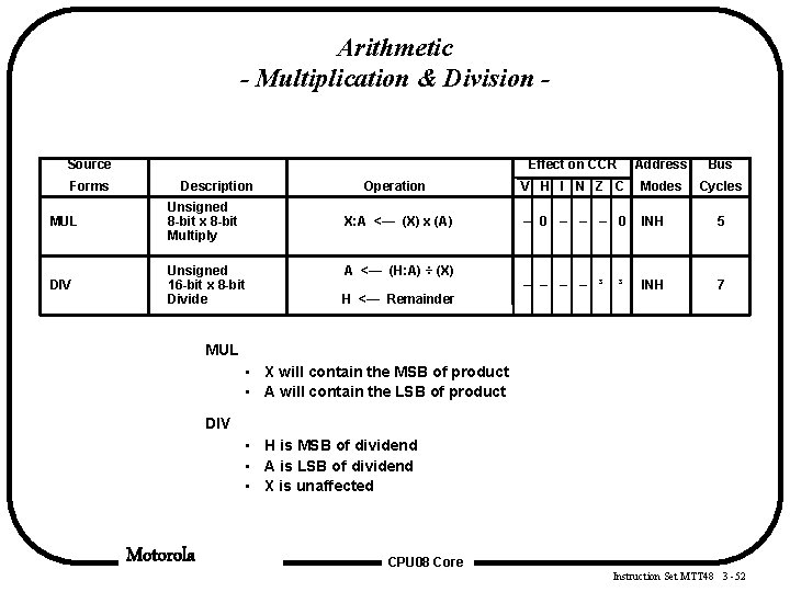
Arithmetic - Multiplication & Division Source Forms Description MUL Unsigned 8 -bit x 8 -bit Multiply DIV Unsigned 16 -bit x 8 -bit Divide Effect on CCR Address Bus Operation V H I N Z C Modes Cycles X: A <— (X) x (A) – 0 – – – 0 INH 5 – – ³ INH 7 A <— (H: A) ÷ (X) H <— Remainder ³ MUL • X will contain the MSB of product • A will contain the LSB of product DIV • H is MSB of dividend • A is LSB of dividend • X is unaffected Motorola CPU 08 Core Instruction Set MTT 48 3 -52
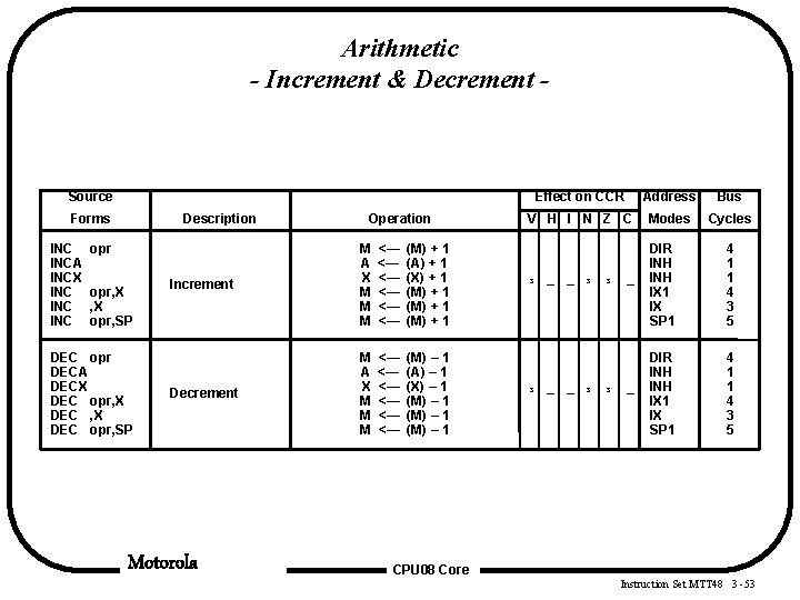
Arithmetic - Increment & Decrement - Source Forms INCA INCX INC INC Description opr, X opr, SP DEC opr DECA DECX DEC opr, SP Operation Increment M A X M M M <— <— <— (M) + 1 (A) + 1 (X) + 1 (M) + 1 Decrement M A X M M M <— <— <— (M) – 1 (A) – 1 (X) – 1 (M) – 1 Motorola Effect on CCR Address Bus V H I N Z C Modes Cycles ³ – – ³ – DIR INH INH IX 1 IX SP 1 4 1 1 4 3 5 ³ – – ³ ³ ³ CPU 08 Core Instruction Set MTT 48 3 -53
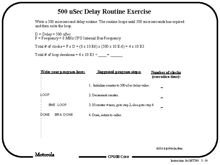
500 u. Sec Delay Routine Exercise Write a 500 microsecond delay routine. The routine loops until 500 microseconds has expired and then exits the loop. D = Delay = 500 u. Sec F = Frequency = 8 MHz CPU Internal Bus Frequency Total # of clocks = F x D = (8 x 10 E 6) x (500 x 10 E-6) = 4 x 10 E 3 Total # of loop iterations = 4 x 10 E 3 ÷ ____ = ______ Write your program here: Suggested program steps: Number of clocks (execution time): 1. Initialize counter to 500 u. Sec delay value. LOOP 2. Decrement counter. BNE LOOP DONE BRA DONE 3. If counter zero, goto step 2, else goto step 4. 4. Done, return to caller. HC 05 -Dly 500 u. Sec. Exer Motorola CPU 08 Core Instruction Set MTT 48 3 -54
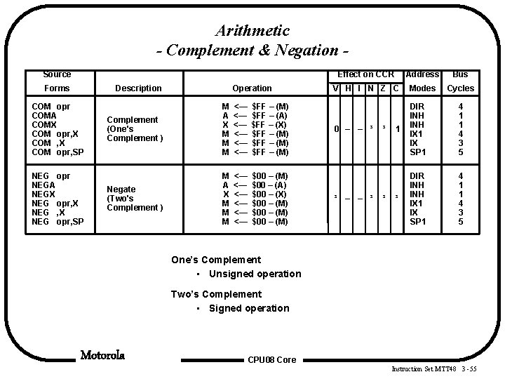
Arithmetic - Complement & Negation Source Forms Description COM opr COMA COMX COM opr, SP NEG opr NEGA NEGX NEG opr, SP Operation Complement (One's Complement ) M A X M M M <— <— <— $FF – (M) $FF – (A) $FF – (X) $FF – (M) Negate (Two's Complement ) M A X M M M <— <— <— $00 – (M) $00 – (A) $00 – (X) $00 – (M) Effect on CCR Address Bus V H I N Z C Modes Cycles 0 – – ³ 1 DIR INH INH IX 1 IX SP 1 4 1 1 4 3 5 ³ – – ³ ³ ³ One’s Complement • Unsigned operation Two’s Complement • Signed operation Motorola CPU 08 Core Instruction Set MTT 48 3 -55
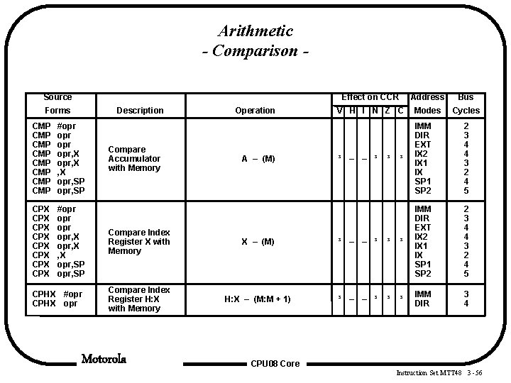
Arithmetic - Comparison Source Forms Description CMP CMP #opr opr opr, X , X opr, SP CPX CPX #opr opr opr, X , X opr, SP CPHX #opr CPHX opr Compare Accumulator with Memory Operation A – (M) Effect on CCR Address Bus V H I N Z C Modes Cycles ³ – – ³ ³ IMM DIR EXT IX 2 IX 1 IX SP 1 SP 2 2 3 4 4 3 2 4 5 3 4 ³ Compare Index Register X with Memory X – (M) ³ – – ³ ³ ³ IMM DIR EXT IX 2 IX 1 IX SP 1 SP 2 Compare Index Register H: X with Memory H: X – (M: M + 1) ³ – – ³ ³ ³ IMM DIR Motorola CPU 08 Core Instruction Set MTT 48 3 -56
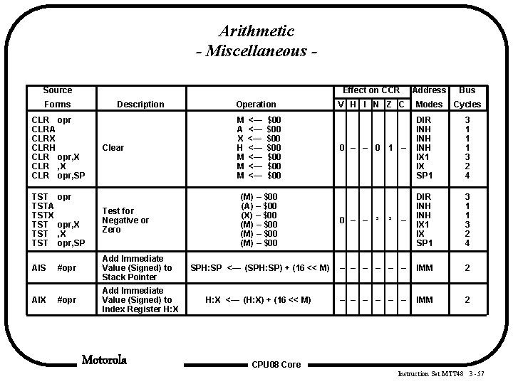
Arithmetic - Miscellaneous Source Forms Description CLR opr CLRA CLRX CLRH CLR opr, X CLR opr, SP TSTA TSTX TST TST Clear opr, X opr, SP Test for Negative or Zero AIS #opr Add Immediate Value (Signed) to Stack Pointer AIX #opr Add Immediate Value (Signed) to Index Register H: X Motorola Effect on CCR Address Bus V H I N Z C Modes Cycles 0 – – 0 1 – DIR INH INH IX 1 IX SP 1 3 1 1 1 3 2 4 0 – – ³ – DIR INH IX 1 IX SP 1 3 1 1 3 2 4 SPH: SP <— (SPH: SP) + (16 << M) – – – IMM 2 H: X <— (H: X) + (16 << M) – – – IMM 2 Operation M A X H M M M <— <— $00 $00 (M) – $00 (A) – $00 (X) – $00 (M) – $00 ³ CPU 08 Core Instruction Set MTT 48 3 -57
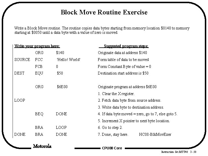
Block Move Routine Exercise Write a Block Move routine. The routine copies data bytes starting from memory location $0140 to memory starting at $0050 until a data byte with a value of zero is moved. Write your program here: SOURCE DEST Suggested program steps: ORG $140 Originate data at address $140 FCC 'Hello! World' Form table of data to be moved FCB 0 Form Constant Byte of value = 0 EQU $50 Destination start address is $50 ORG $6 E 00 Originate program at address $6 E 00 1. Clear the X register. LOOP 2. Fetch data byte from source address. 3. Write data byte to destination address. BEQ DONE 4. If data byte moved = zero, go to 7, else goto 5. 5. Increment X pointer to next byte location. DONE BRA LOOP 6. Go to step 2. BRA DONE 7. Done, stay here. Motorola HC 08 -Blk. Mov. Exer CPU 08 Core Instruction Set MTT 48 3 -58
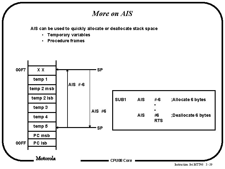
More on AIS can be used to quickly allocate or deallocate stack space • Temporary variables • Procedure frames 00 F 7 XX SP temp 1 temp 2 msb AIS #-6 temp 2 lsb temp 3 SUB 1 AIS #6 AIS temp 4 temp 5 AIS #-6 • • #6 RTS ; Allocate 6 bytes ; Deallocate 6 bytes SP PC msb 00 FF PC lsb Motorola CPU 08 Core Instruction Set MTT 48 3 -59
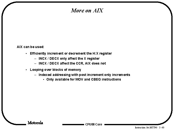
More on AIX can be used: • Efficiently increment or decrement the H: X register – INCX / DECX only affect the X register – INCX / DECX affect the CCR, AIX does not • Looping over blocks of memory – Indexed addressing with post increment only increments • Only available for MOV and CBEQ instructions Motorola CPU 08 Core Instruction Set MTT 48 3 -60
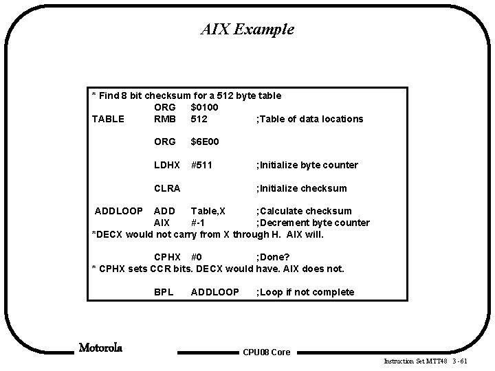
AIX Example * Find 8 bit checksum for a 512 byte table ORG $0100 TABLE RMB 512 ; Table of data locations ORG $6 E 00 LDHX #511 CLRA ; Initialize byte counter ; Initialize checksum ADDLOOP ADD Table, X ; Calculate checksum AIX #-1 ; Decrement byte counter *DECX would not carry from X through H. AIX will. CPHX #0 ; Done? * CPHX sets CCR bits. DECX would have. AIX does not. BPL Motorola ADDLOOP ; Loop if not complete CPU 08 Core Instruction Set MTT 48 3 -61
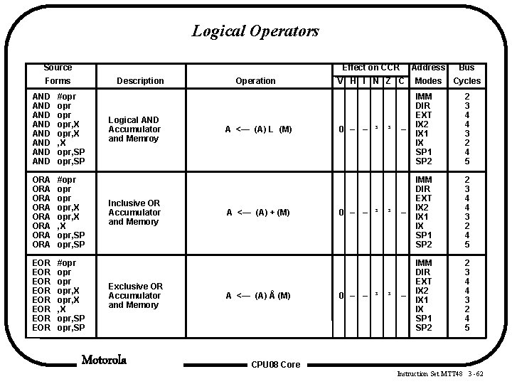
Logical Operators Source Forms Description AND AND #opr opr opr, X , X opr, SP ORA ORA #opr opr opr, X , X opr, SP EOR EOR #opr opr opr, X , X opr, SP Logical AND Accumulator and Memroy Inclusive OR Accumulator and Memory Exclusive OR Accumulator and Memory Motorola Operation A <— (A) L (M) A <— (A) + (M) A <— (A) Å (M) Effect on CCR Address Bus V H I N Z C Modes Cycles 0 – – ³ – IMM DIR EXT IX 2 IX 1 IX SP 1 SP 2 2 3 4 4 3 2 4 5 0 – – ³ ³ ³ ³ CPU 08 Core Instruction Set MTT 48 3 -62
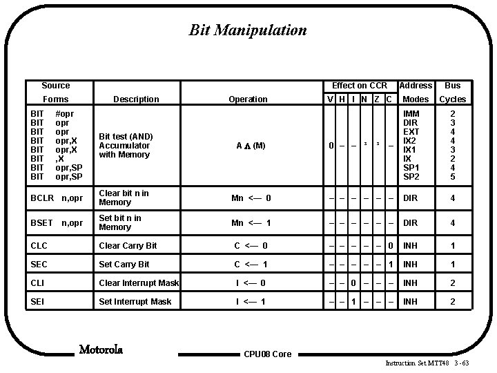
Bit Manipulation Source Forms BIT BIT Description #opr opr opr, X , X opr, SP Operation Effect on CCR Address Bus V H I N Z C Modes Cycles 0 – – ³ – IMM DIR EXT IX 2 IX 1 IX SP 1 SP 2 2 3 4 4 3 2 4 5 Bit test (AND) Accumulator with Memory A (M) BCLR n, opr Clear bit n in Memory Mn <— 0 – – – DIR 4 BSET Set bit n in Memory Mn <— 1 – – – DIR 4 n, opr ³ CLC Clear Carry Bit C <— 0 – – – 0 INH 1 SEC Set Carry Bit C <— 1 – – – 1 INH 1 CLI Clear Interrupt Mask I <— 0 – – – INH 2 SEI Set Interrupt Mask I <— 1 – – – INH 2 Motorola CPU 08 Core Instruction Set MTT 48 3 -63
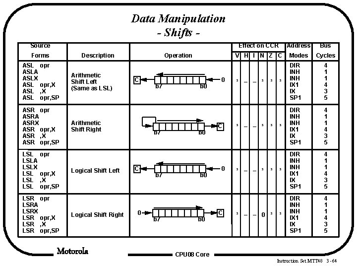
Data Manipulation - Shifts Source Forms Description ASL opr ASLA ASLX ASL opr, SP ASR opr ASRA ASRX ASR opr, SP LSLA LSLX LSL LSL Arithmetic Shift Left (Same as LSL) Operation C Arithmetic Shift Right b 7 b 0 0 C Effect on CCR Address Bus V H I N Z C Modes Cycles ³ – – ³ ³ DIR INH INH IX 1 IX SP 1 4 1 1 4 3 5 ³ – – ³ ³ ³ opr, X opr, SP LSR opr LSRA LSRX LSR opr, SP Logical Shift Left Logical Shift Right Motorola C 0 b 7 b 0 0 C ³ – – ³ ³ ³ – – 0 ³ CPU 08 Core Instruction Set MTT 48 3 -64
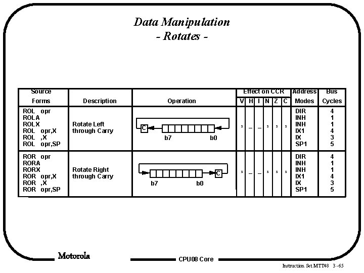
Data Manipulation - Rotates - Source Forms Description ROL opr ROLA ROLX ROL opr, SP ROR opr RORA RORX ROR opr, SP Rotate Left through Carry Operation C b 7 Motorola Address Bus V H I N Z C Modes Cycles ³ – – ³ ³ DIR INH INH IX 1 IX SP 1 4 1 1 4 3 5 ³ b 0 Rotate Right through Carry C b 7 Effect on CCR b 0 ³ – – ³ ³ CPU 08 Core Instruction Set MTT 48 3 -65
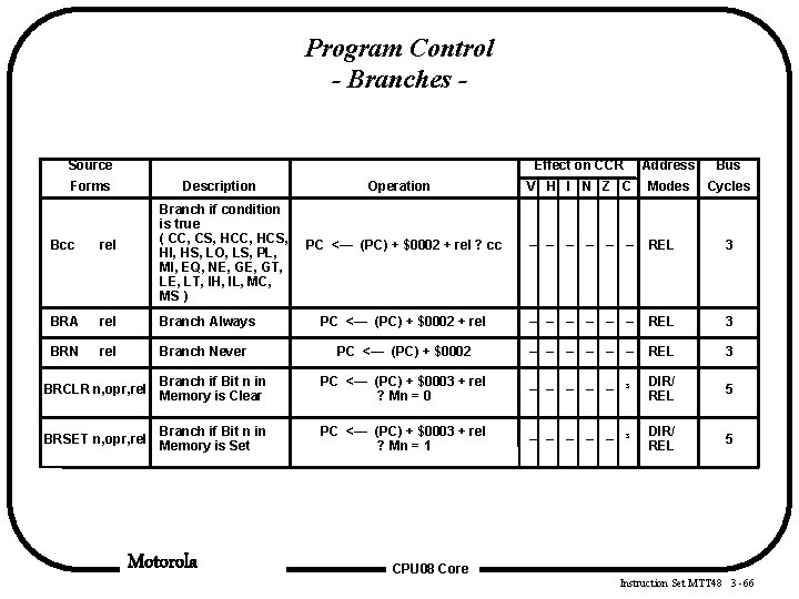
Program Control - Branches Source Effect on CCR Address Bus V H I N Z C Modes Cycles PC <— (PC) + $0002 + rel ? cc – – – REL 3 PC <— (PC) + $0002 + rel – – – REL 3 PC <— (PC) + $0002 – – – REL 3 Branch if Bit n in BRCLR n, opr, rel Memory is Clear PC <— (PC) + $0003 + rel ? Mn = 0 – – – ³ DIR/ REL 5 Branch if Bit n in BRSET n, opr, rel Memory is Set PC <— (PC) + $0003 + rel ? Mn = 1 – – – ³ DIR/ REL 5 Forms Description Branch if condition is true ( CC, CS, HCC, HCS, HI, HS, LO, LS, PL, MI, EQ, NE, GT, LE, LT, IH, IL, MC, MS ) Bcc rel BRA rel Branch Always BRN rel Branch Never Motorola Operation CPU 08 Core Instruction Set MTT 48 3 -66
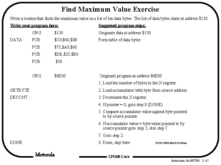
Find Maximum Value Exercise Write a routine that finds the maximum value in a list of ten data bytes. The list of data bytes starts at address $130. Write your program here: DATA Suggested program steps: ORG $130 Originate data at address $130 FCB $C 0, $40, $8 B Form table of data bytes FCB $75, $A 0, $60 FCB $DB, $25, $B 0 FCB $50 ORG $6 E 00 Originate program at address $6 E 00 1. Load the number of bytes in the X register. GETBYTE 2. Load accumulator with byte from source address. DECCNT 3. Decrement the X register. 4. If pointer = 0, goto step 8 (DONE) 5. Compare accumulator value against byte pointed to by source pointer. 6. If accumulator value = byte value pointed to by source pointer goto step 3, else step 7. 7. Goto step 2. DONE 8. Done, stay here. Motorola HC 08 -FINDMAXVALExer CPU 08 Core Instruction Set MTT 48 3 -67
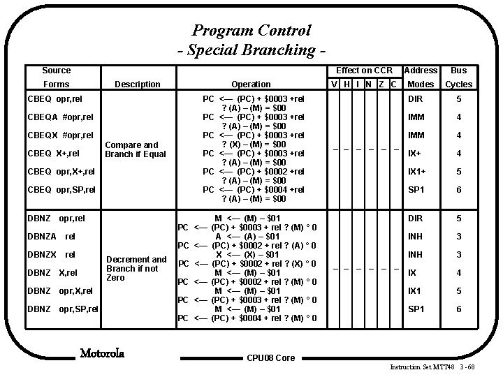
Program Control - Special Branching Source Forms Description CBEQ opr, rel CBEQA #opr, rel CBEQX #opr, rel Compare and Branch if Equal CBEQ X+, rel CBEQ opr, SP, rel DBNZ opr, rel DBNZA rel DBNZX rel Decrement and Branch if not Zero DBNZ X, rel DBNZ opr, SP, rel Motorola Operation PC <— (PC) + $0003 +rel ? (A) – (M) = $00 PC <— (PC) + $0003 +rel ? (X) – (M) = $00 PC <— (PC) + $0003 +rel ? (A) – (M) = $00 PC <— (PC) + $0002 +rel ? (A) – (M) = $00 PC <— (PC) + $0004 +rel ? (A) – (M) = $00 M <— (M) – $01 PC <— (PC) + $0003 + rel ? (M) ° 0 A <— (A) – $01 PC <— (PC) + $0002 + rel ? (A) ° 0 X <— (X) – $01 PC <— (PC) + $0002 + rel ? (X) ° 0 M <— (M) – $01 PC <— (PC) + $0002 + rel ? (M) ° 0 M <— (M) – $01 PC <— (PC) + $0003 + rel ? (M) ° 0 M <— (M) – $01 PC <— (PC) + $0004 + rel ? (M) ° 0 Effect on CCR Address Bus V H I N Z C Modes Cycles – – – DIR 5 IMM 4 IX+ 4 IX 1+ 5 SP 1 6 DIR 5 INH 3 IX 4 IX 1 5 SP 1 6 CPU 08 Core Instruction Set MTT 48 3 -68
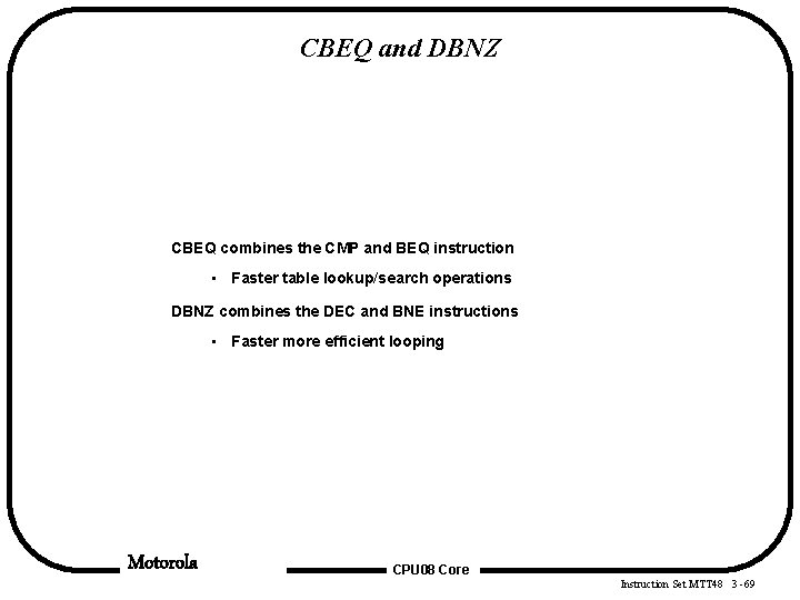
CBEQ and DBNZ CBEQ combines the CMP and BEQ instruction • Faster table lookup/search operations DBNZ combines the DEC and BNE instructions • Faster more efficient looping Motorola CPU 08 Core Instruction Set MTT 48 3 -69
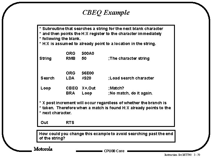
CBEQ Example * Subroutine that searches a string for the next blank character * and then points the H: X register to the character immediately * following the blank. * H: X is assumed to already point to a location in the string. String ORG RMB $00 A 0 50 ; The character string Search ORG LDA $6 E 00 #$20 ; Load search character Loop CBEQ X+, Out BRA Loop ; Match? ; No match, do it again. * X post increment will occur regardless of whether the branch is * taken. Therefore when a match is found H: X already points to the * next character. Out RTS How could you change this example to avoid searching past the end of the string? Motorola CPU 08 Core Instruction Set MTT 48 3 -70
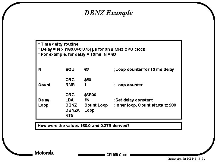
DBNZ Example * Time delay routine * Delay = N x (160. 0+0. 375) µs for an 8 MHz CPU clock * For example, for delay = 10 ms N = 63 N EQU 63 ; Loop counter for 10 ms delay Count ORG RMB $50 1 ; Loop counter ORG LDA DBNZA RTS $6 E 00 #N Count, Loop Delay Loop ; Set delay constant ; Inner loop, Count starts at $00 How were the values 160. 0 and 0. 375 derived? Motorola CPU 08 Core Instruction Set MTT 48 3 -71
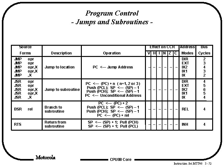
Program Control - Jumps and Subroutines - Source Forms Description Effect on CCR Address Bus V H I N Z C Modes Cycles – – – DIR EXT IX 2 IX 1 IX 2 3 4 3 2 PC <— (PC) + n ( n=1, 2 or 3 ) Push (PCL); SP <— (SP) – 1 Push (PCH); SP <— (SP) – 1 PC <— Unconditional Address – – – DIR EXT IX 2 IX 1 IX 4 5 6 5 4 Operation JMP JMP JMP opr opr, X , X JSR JSR JSR opr opr, X , X Jump to subroutine rel Branch to subroutine PC <— (PC) + 2 Push (PCL); SP <— (SP) – 1 Push (PCH); SP <— (SP) – 1 PC <— (PC) + rel – – – REL 4 Return from subroutine SP <— (SP) + 1; Pull (PCH) SP <— (SP) + 1; Pull (PCL) – – – INH 4 BSR RTS Jump to location Motorola PC <— Jump Address CPU 08 Core Instruction Set MTT 48 3 -72
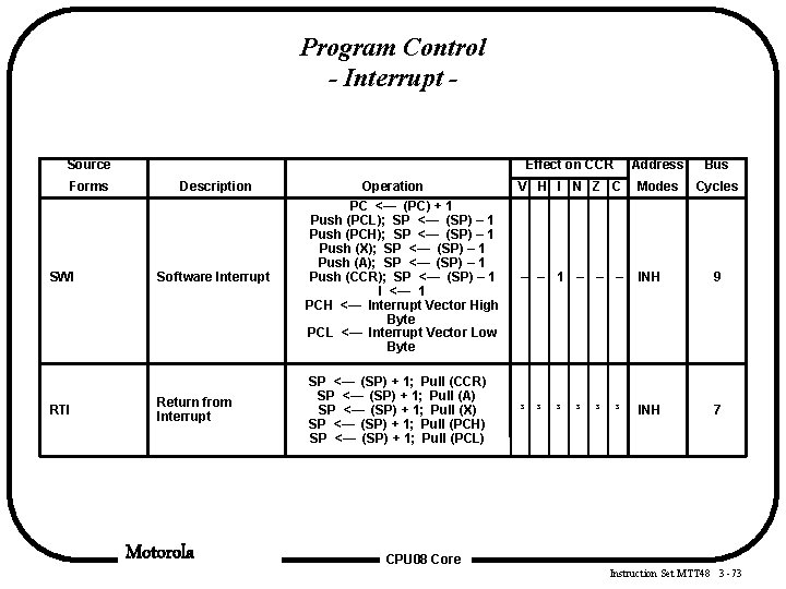
Program Control - Interrupt Source Forms SWI RTI Description Software Interrupt Return from Interrupt Motorola Operation PC <— (PC) + 1 Push (PCL); SP <— (SP) – 1 Push (PCH); SP <— (SP) – 1 Push (X); SP <— (SP) – 1 Push (A); SP <— (SP) – 1 Push (CCR); SP <— (SP) – 1 I <— 1 PCH <— Interrupt Vector High Byte PCL <— Interrupt Vector Low Byte SP <— (SP) + 1; Pull (CCR) SP <— (SP) + 1; Pull (A) SP <— (SP) + 1; Pull (X) SP <— (SP) + 1; Pull (PCH) SP <— (SP) + 1; Pull (PCL) Effect on CCR Address Bus V H I N Z C Modes Cycles – – 1 – – – INH 9 ³ ³ INH 7 ³ ³ CPU 08 Core Instruction Set MTT 48 3 -73
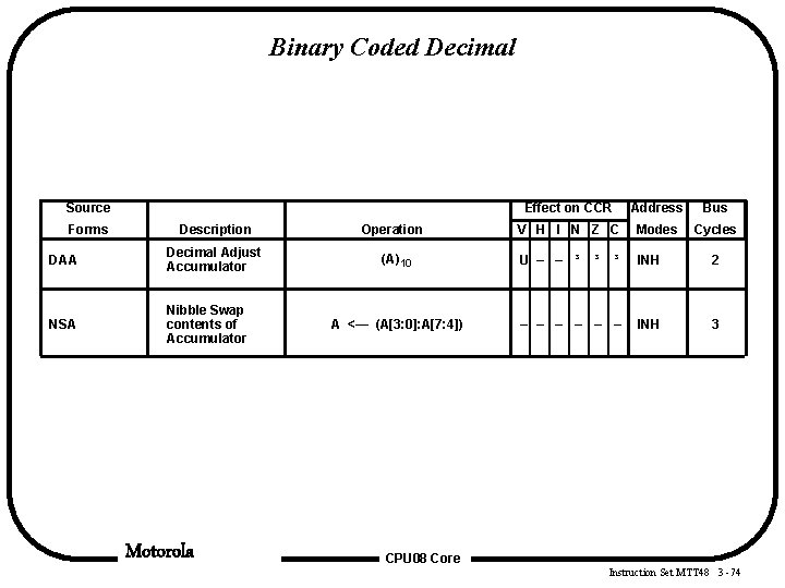
Binary Coded Decimal Source Forms Description DAA Decimal Adjust Accumulator NSA Nibble Swap contents of Accumulator Motorola Operation (A)10 A <— (A[3: 0]: A[7: 4]) Effect on CCR Address Bus V H I N Z C Modes Cycles U – – ³ ³ INH 2 – – – INH 3 ³ CPU 08 Core Instruction Set MTT 48 3 -74
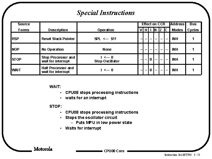
Special Instructions Source Forms Effect on CCR Address Bus Cycles Description Operation V H I N Z C Modes RSP Reset Stack Pointer SPL <— $FF – – – INH 1 NOP No Operation None – – – INH 1 STOP Stop Processor and wait for interrupt I <— 0 Stop Oscillator – – 0 – – – INH 1 WAIT Halt Processor and wait for interrupt I <— 0 – – – INH 1 WAIT: • CPU 08 stops processing instructions • waits for an interrupt STOP: • CPU 08 stops processing instructions • Stops the oscillator circuit – Puts MPU in low power state • Waits for interrupt Motorola CPU 08 Core Instruction Set MTT 48 3 -75