ENTC 1110 Multiview Drawings The Six Principal Views


- Slides: 45
ENTC 1110 Multiview Drawings
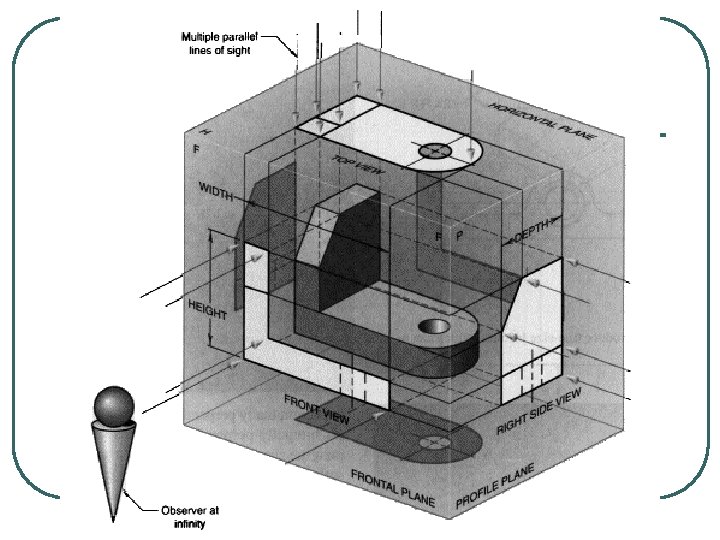
The Six Principal Views l l The plane of projection can be oriented to produce an infinite number of views of an object. However, some views are more important than others. • These principal views are the six mutually perpendicular views that are produced by six mutually perpendicular planes of projection.
l If you imagine suspending an object in a glass box with major surfaces of the object positioned so that they are parallel to the sides of the box, the six sides of the box become projection planes showing the six views.
l The six principal views are • front, • top, • left side, • right side, • bottom. and • rear.
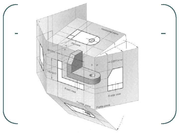
l l To draw these views on 2 -D media, that is, a piece of paper or a computer monitor, imagine putting hinges on all sides of the front glass plane and on one edge of the left profile plane. Then cut along all the other comers. and flatten out the box to create a six-view drawing.
l The front view is the one that shows the most features or characteristics. • All other views are based on the orientation • chosen for the front view. Also. all other views, except the rear view. are formed by rotating the lines of sight 90 degrees in an appropriate direction from the front view.
l l The top view shows what is the top of the object once the position of the front view is established. The right side view shows what is the right side of the object once the position of the front view is established.
l The left side view shows what is the left side of the object once the position of the front view is established. • l The left side view is a mirror image of the right side view, except that hidden features are different. The rear view shows what becomes the rear of the object once the front view is established. • The rear view is at 90 degrees to the left side view and is a mirror image of the front view, except that hidden features are different.
l The bottom view shows what becomes the bottom of the object once the front view is established. • The view is a mirror image of the top view, except that hidden features are different.
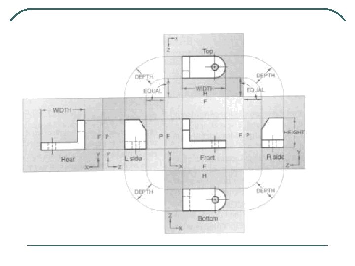
l The concept of laying the views flat by unfolding glass box forms the basis for two important multiview drawing standards: 1. Alignment of views. 2. Fold lines.
l l The top, front, and bottom views are all aligned vertically and share the same width dimension. The rear, left side, front, and right side views are all aligned horizontally and share the same height dimension.
l Fold lines are the imaginary hinged edges of the glass box
Conventional View Placement l l The three-view multiview drawing is the standard used in engineering and technology, because many times the other three principal views are mirror images and do not add to the knowledge about the object. The standard views used in a three-view drawing are the: • • • top view, front view, and right side view.
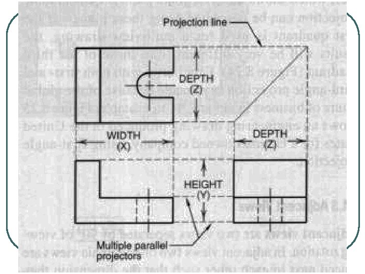
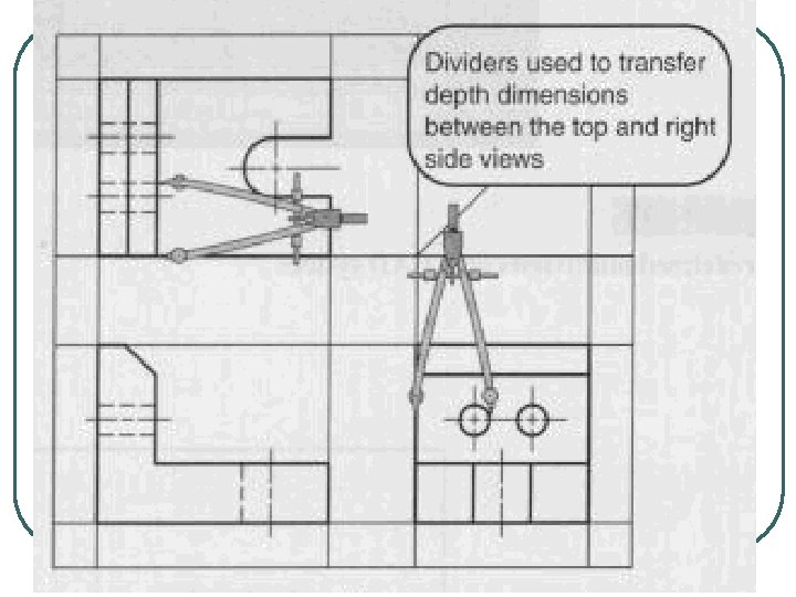
l l The width dimensions are aligned between front and top views, using vertical projection lines. The height dimensions are aligned between the front and profile views, using horizontal projection lines.
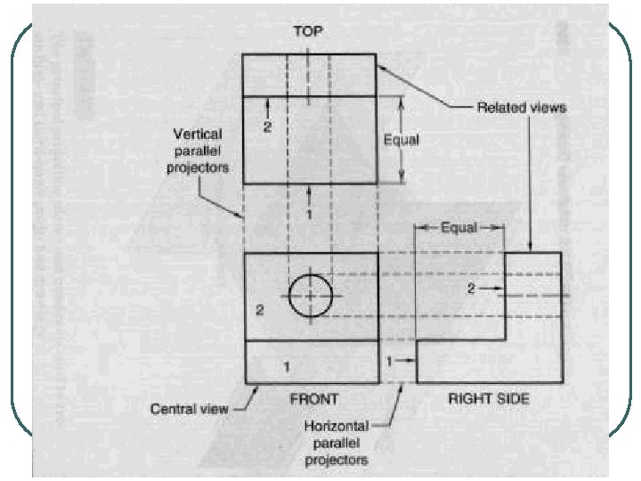
l Adjacent views are two views separated by 90 of viewing rotation. • In adjacent views two orthographic views are placed next to each other such that the dimension they share in common are aligned.
l The top and front views share the width dimension. • The top view is placed directly above the front view, and vertical parallel projectors are used to ensure alignment of the shared width dimension.
l The right side and front views share the height dimension; therefore, the right side view is placed directly to the right of the front view, and horizontal parallel projectors are used to ensure alignment.
Principles of Orthographic Projections—Rule 1: l Alignment of Features • Every point or feature in one view must be aligned on a parallel projector in any adjacent view. • The distance between the views is not fixed, and it can vary according to the space available on the paper and the number of dimensions to be shown.
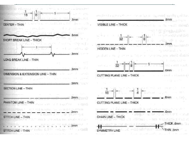
Line Conventions l l Center lines are used to represent symmetry and to mark the centers of circles and the axes of symmetrical parts, such as cylinders and bolts. Break lines come in two forms: a freehand thick line and a long, ruled thin line with zigzags. • Break lines are used to show where an object is broken to save drawing space or reveal interior features.
l l l Dimension and extension lines are used to indicate the sizes of features on a drawing. Section lines are used in section views to represent surfaces of an object cut by a cutting plane. Cutting plane lines are used in section drawings to show the locations of cutting planes.
l l Visible lines are used to represent features that can be seen in the current view. Hidden lines are used to represent features that cannot be seen in the current viet. Phantom lines are used to represent a moveable feature in its different positions. Stitch lines are used to indicate a sewing or stitching process.
l l Chain lines are used to indicate that a surface is to receive additional treatment. Symmetry lines are used as an axis of symmetry for a particular view.
One- and Two-View Drawings l Some objects can be adequately described with only one view. • • A sphere can be drawn with one because all views will be a circle. A cylinder or cube described with one view if a note is added to describe missing feature or dimension. Other applications include a thin gasket or a printed circuit board. One-view drawings are used in electrical. civil, and construction engineering.
l Other objects can he adequately described with two-views. • Cylindrical, conical, and pyramidal shapes are examples of such objects. • For example. a cone can described with a front and a top view. A profile would be the same as the front view.
Three-View Drawings l The majority of objects require three views to completely describe the objects.
l The following steps describe basics for setting up and developing a three-view drawing of a simple part.
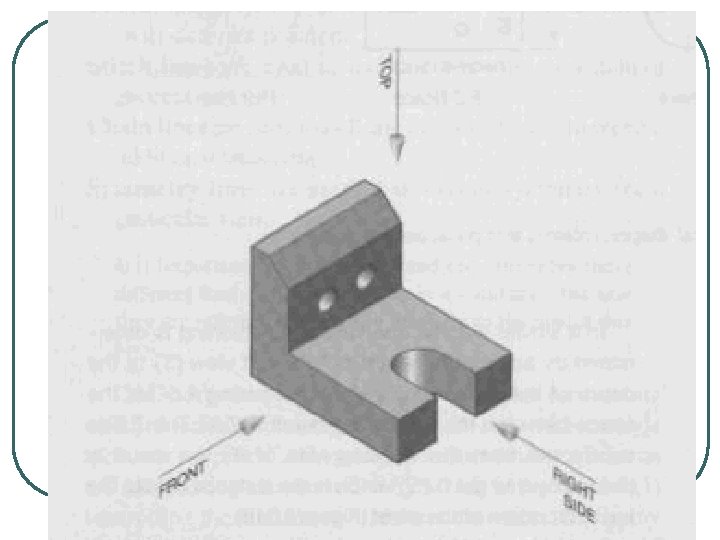
Step 1 l The isometric view of the part represents the part in its natural position; it appears to be resting on its largest surface area. • The front, right side, top views are selected such that the fewest hidden lines would appear on the views.
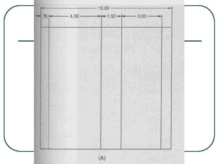
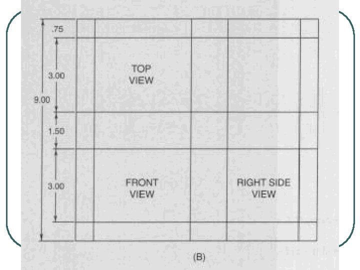
Step 2 l The spacing of the views is determined by the width, height, and depth of the object. • Views are spaced to center the drawing within • the working area of the drawing sheet. Also, the distance between views can vary, but enough space should be left so that dimensions can be placed between the views.
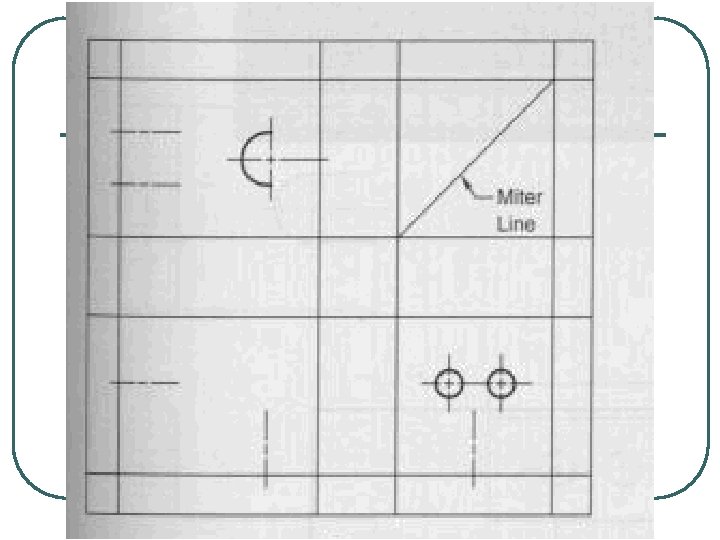
Step 3: l Locate the center lines in each view, and lightly draw the arc and circles.
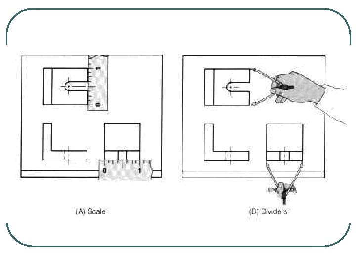
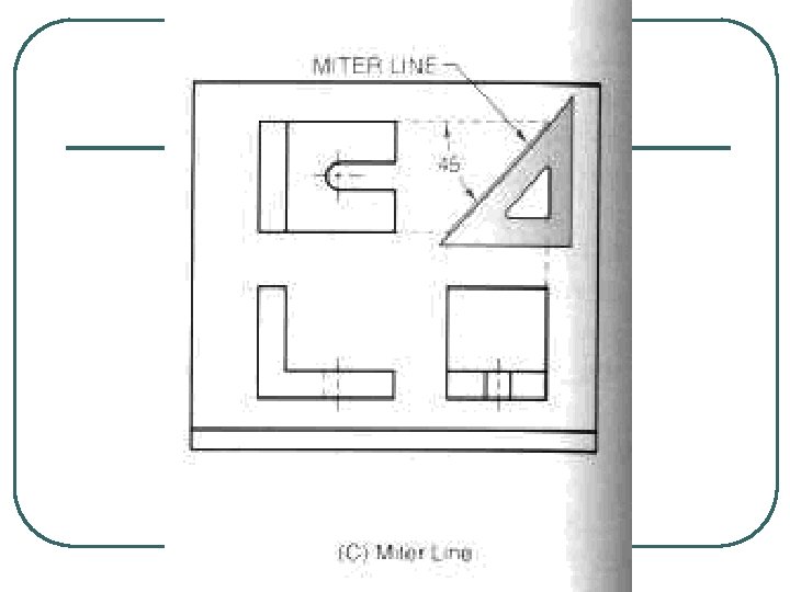
Step 4: l Locate other details, and lightly draw horizontal, vertical, and inclined lines in each view. • Normally the front view is constructed first because it has the most detail. • These details are then projected to the other views using construction lines.
Step 5: l Locate and lightly draw hidden lines in each view.
Step 6: l Following the alphabet of lines, darken all object lines by doing all horizontal, then all vertical, and finally all inclined lines, in that order. • Darken all hidden and center lines. • Lighten or erase any construction lines that can be easily seen when the drawing is held at arm’s length.