Chapter 10 MultiView Drawings Copyright The Mc GrawHill


- imaginary ray of light between an observers eye and an")


 • Frontal (_____ & ____) • Horizontal (_____")


 • Aligned views")


 vs. Rounds (Exterior Corner) on Planes What is difference between a")


- Slides: 30
Chapter 10 Multi-View Drawings Copyright © The Mc. Graw-Hill Companies, Inc. Permission required for reproduction or display.
Projection Theory. Represent 3 D objects on 2 D media to give a clear understanding what the part looks like 2 Variables • Line of Sight (LOS) • Plane of Projection (Paper)
Line of Sight (LOS)- imaginary ray of light between an observers eye and an object Plane of Projection- Flat plane where is projected (always perpendicular from LOS) 90° Any > 3 D
Perspective- all lines originate from finite distance of sight at a single point Different distances change what it will look like How we see it! Real Life
Parallel- all lines of sight are parallel (part positioned parallel to picture plane at infinite distance) Imaginary Not Real Life
Planes of Projection (Dimension they provide) • Frontal (_____ & ____) • Horizontal (_____ & ______) • Profile (_____ & _____) Solid Works calls these planes what? What is the minimum # of views to get all 3 dimension of a part?
Types of Drawings • One View • Two View • Three View What are some examples of each?
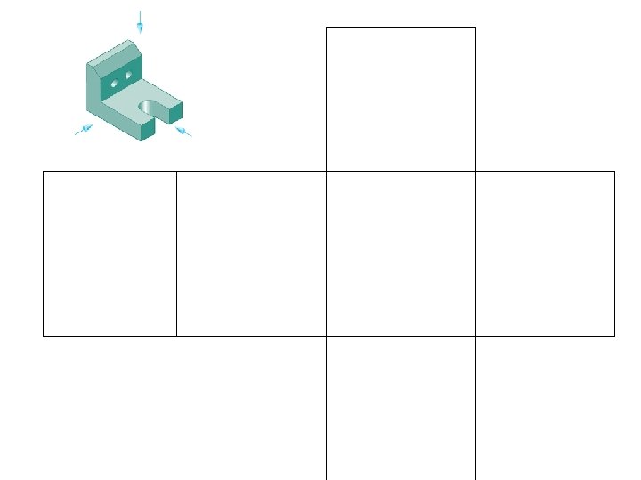
Understanding Exercise • Identify which plane of projection the view asked for is projected onto • Identify which of the 4 views is the correctly projected according to the arrow or view direction
Multi-View Projection vs. Perspective • No distorted surfaces or dimensions (Scalable) • Aligned views fill in gaps of confusion What is not clear with the isometric alone?
6 Principle Views 3 views conventionally used: ______ , _____, and _______ What do they call it in Solid Works?
Rules to select Views: • Most Descriptive views • Natural Orientation • Minimum # of views • No dimensions to hidden lines
Number of Views and Which is Front View?
First Angle Projection VS. Third Angle Projection 3 names you might hear? Back to Front to Back
Number of Views and Which is Front View? Homework
Tangency on Planes
SOLID WORKS TEMPLATE SETTINGS
SOLID WORKS TEMPLATE SETTINGS
SOLID WORKS TEMPLATE DRAFTING SETTINGS
SOLID WORKS TEMPLATE SETTINGS
Fillets (Interior Corner) vs. Rounds (Exterior Corner) on Planes What is difference between a fillet/ round & a chamfer? 2 ways to define chamfer _____ x ______& ______ x ______
Runout- corners where fillets intersect cylinders
Edge line Types • Normal • Inclined • Oblique Comparison Chart True Length/Foreshortened/ Point view
Planes of a part • Normal • Inclined • Oblique What do we have to create to show true shape and size of an inclined or oblique plane? Comparison Chart True Size & Shape/Foreshortened / Edge
Why do we care? How do I really locate where to drill the hole?
Understanding Exercise • Identify what line or plane type is represented in the example below.
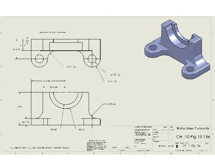
Partial Views. Show only necessary information to convey design intent • Use Break or Center line Noted: Some hidden lines removed for clarity
Removed Views AKA Detailed Views Why is scale noted in other views?
Homework Determine Front View Minimum# of views Tangencies removed All needed dimensions