Drawings Review Drawings Drawings are used to communicate


 • Geometric Layout: – Set of lines that form")
 • Dimensioning – The inclusion on a technical drawing")


 – Exploded view – Cross-section: • Drawing of an object")
 – Sections • Partial representation of an object that presents")
 Definition: – A projection is a representation of a 3 dimensional")


 Types of Projections • A) Multiview Projection: – Definition: • A 2 dimension")

 Types of Projections • B) Isometric Projection: – Definition: • A drawing depicting")

 Types of Projections • 2. Oblique Projections – Definition: • A drawing depicting")


 Definition: • A motion transmission system transmits the same type")


 Types of motion transmission systems 1. 2. 3. 4. 5. Gear")


 Definition • Relaying a motion from one part to another while")

 – Contains a screw and")
 into Cam and Follower – Rotational motion changed translation motion When")


- Slides: 46
Drawings Review
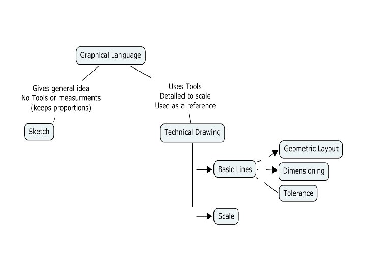
Drawings • Drawings are used to communicate information – Sketch: • A drawing done without instruments or measurements, but conveys the general idea and proportions – Technical Drawing: • Serves as a reference and presences all information is drawn with tools and is to scale
Drawings – Technical Drawings (cont) • Geometric Layout: – Set of lines that form a technical drawing • Basic Lines: – the standard graphic symbols that form a technical drawing (allow it to be a reference document)
Drawings – Technical Drawings (cont) • Dimensioning – The inclusion on a technical drawing of the dimension required to manufacture (create) an object » Use dimension lines and extension lines • Tolerance – The imprecision allowed between a part’s actual dimensions and the corresponding dimensions that appear on a technical drawing
Drawings • Scale: – The relationship between an object’s dimensions in a drawing and the actual dimensions of the object » Full-size scale or actual-size scale » Reduction scale: drawing is smaller than real life » Enlargement scale: drawing is bigger than real life
Projections • Projections: – a 3 D representation of an object in 2 D • Types of Projections: – Orthogonal Projections: • Multiview (Orthographic) - Top, Front, Right view • Isometric – Oblique projections
Projections • Projections (cont) – Exploded view – Cross-section: • Drawing of an object as if it were cut by a cutting plane line
Projections • Projections (cont) – Sections • Partial representation of an object that presents only the object’s surface on the cutting plane • Types of section: – Revolved – Removed
Projections • A) Definition: – A projection is a representation of a 3 dimensional object in two dimensions – Uses Basic Lines • B) Types of projections – 1. Orthogonal Projections • Multiview • Isometric – 3. Oblique Projections
Multiview Projection
Isometric Projection
Oblique Projection
B) Types of Projections • A) Multiview Projection: – Definition: • A 2 dimension representation of different views (faces) of an object (usually front, top and right side) – Advantages: • Provides a complete description of the object • Allows for the representation of all the measurements to scale or as is
Multiview Top View Front view Right side view
B) Types of Projections • B) Isometric Projection: – Definition: • A drawing depicting all 3 dimensions of an object • The axis (x, y, z) are at 120 degree angles of each other.
Isometric • The edge of your shape is facing the page • You can see all three angles without distortions
B) Types of Projections • 2. Oblique Projections – Definition: • A drawing depicting all 3 dimensions of an object where one side is parallel to the paper – This distorts the depth of the object
* Please Note • For construction purposes: – Use a combination of multiview and isometric projections as they show the overall design – For a more detailed drawing showing all the parts, we have an exploded view
** Exploded view • Purpose: – Projection accompanying the assembly instructions or specifications of an object – Made up of different parts which are drawn separately from one another • Exploded views include: – The names of each part (the nomenclature), the quantity and bill of materials (material list)
1. Diagrams • 3. Standards in diagrams – Symbols for Force • Compression • Tension • Shearing – Symbols for movement • Translational • Rotational • Helical
1. Diagrams • 3. Standards in diagrams – Symbols for parts • Screw/bolt • Nut – Symbols for guides • Translational • Rotational
Motion Transmission Systems
Motion Transmission • A) Definition: • A motion transmission system transmits the same type of motion from one part of an object to another • For example: rotational to rotational
Specific system vocabulary – Motion transmission systems contain: – A driver: a component that initiates the motion – At least a driven component: that receive the motion and transfers it – Some systems might also contain intermediate components between the driver and driven components Driven Driver Intermediate
Specific system vocabulary • Reversibility: – A system is considered “reversible” when the driven component could become the driver unit, and it would not change any of the motion types
Motion Transmission B) Types of motion transmission systems 1. 2. 3. 4. 5. Gear Train Chain and Sprocket Worm and Screw gear Friction Gears Belt and pulley
Motion Transmission 1. Gear trains • Contains at least two gears that meet and mesh together Direction of Alternates from components one gear to another Reversibility Yes
Motion Transmission When building a gear train, you must consider: 1. The Gear teeth (they must be evenly spaced, the same size and have the same direction) 2. The Gear types (straight gears vs. bevel gears) 3. The Gear size (the higher the number of teeth, the slower the rotation) The larger the diameter the slower the rotation
Motion Transmission 2. Chain and sprocket • Connects components that are far away from one another. • The gears do not mesh together; they are connected with a chain (or sprocket) Direction of components The sprockets inside the sprocket will turn in the same direction. Reversibility Yes
Motion Transmission When building a chain and sprocket, you must consider that: 1. The teeth on the sprocket are identical 2. The chain links must mesh easily with the sprocket’s teeth 3. The system requires constant lubrification 4. The smaller the sprocket the fastest it turns
Motion Transmission 3. Worm and screw gear – Consists of one endless screw and at least a gear – It is not reversible When building a worm and screw gear, you must ensure that: 1. 2. The gear teeth match the worm’s grooves The driver must be the worm
Motion Transmission 4. Friction gear systems – Similar to gear trains yet less efficient because the friction gears can slip. – The larger the gear the slower the rotation
Motion Transmission 5. Belt and pulley system – When building a belt and pulley system, you must ensure: 1. Pulleys must contain a groove where the belt can fit 2. The belt must adhere to the pulleys 3. The smaller the pulley the faster it turns
Speed Change In Motion Transmission Systems
Speed Change 1. Worm and screw gear • For each turn of the worm, the gear moves by one tooth. The greater the number of teeth the slower the speed.
Speed Change 2. Remaining systems • The speed varies with the number of teeth (or the diameter of the gears) – If motion is transmitted to a smaller gear, the speed is increased – If motion is transmitted to a larger gear, speed is decreased – If motion is transmitted to a gear of equal size, there is no speed change
Motion Transformation systems
Motion Transformation A) Definition • Relaying a motion from one part to another while altering the nature of the motion (e. g. rotation to translation or translation to rotation) B) Types of motion Transformation systems 1. 2. 3. 4. Rack and pinion Screw Gear systems Cam and follower Slider–Crank mechanism
Motion Transformation • 1. Rack and Pinion – Contains a rack (straight bar with teeth) and a pinion (gear) While building a rack and pinion you must ensure that: 1. The teeth on the rack and on the pinion must be identical 2. The system requires frequent lubrification 3. The greater the number of teeth on the pinion the slower the rotation
Motion Transformation • 2. Screw gear systems (2 Types) – Contains a screw and a nut – Type 1: the screw is the driver • Transforms rotational motion into translational motion (e. g. jack to lift the car) – Type 2: the nut is the driver • Transforms translational motion into rotational motion
Motion Transformation 3) into Cam and Follower – Rotational motion changed translation motion When building a cam and follower, you must ensure that: 1. The follower must be guided in its translational motion 2. The shape of the cam determines how the follower will move 3. A device such as a return spring is usually necessary to keep the follower in continual contact with the cam.
Motion Transformation • Eccentric vs. Regular cam – In a regular cam, the axis of rotation is centered. – In an eccentric cam the axis of rotation is off-centered. – – –
Motion Transmission • 4. Slider-crank mechanism – This is the mechanisms used in pistons