Engineering Drawing Essential Questions Why are engineering drawings


- Slides: 42
Engineering Drawing Essential Questions: Why are engineering drawings important? What kinds of drawings are most useful to engineers and why?
Measurement The first step in creating and understanding engineering drawings is accurate measurement.
Reading a Ruler When reading a ruler, you want to find out how far the item is from zero. When reading a ruler, you must locate the zero marking, this may vary depending on the ruler. On some rulers, the zeros start at the end, but on others it starts about 1/4 of an inch from the end. If you do not check your ruler beforehand you will not be getting an accurate measurement.
Types of Measurements Standard – inches, feet, yards, and miles Metric – millimeters, centimeters, decimeters, decameters, kilometers, etc.
Reading a Standard Ruler
The Standard Measurement A B C D
Scale is a ratio of a length used in a drawing to portray the actual length of the object. In the drawing below, 1 inch represents 2 inches on the actual box so the scale is 1/2 or 1: 2. 1” Drawing 2” 1” 2”
Practicing Scale Keeping with the 1: 2 scale from the last slide, what would the scaled dimensions be in a drawing of the actual block shown below? Sketch the drawing and record the 1: 2 scale in your design notebook. 1: 2 scale H= ____ W= ____ L= ____ H=2” What would the scale be if you wanted to make it 3 times bigger? L=3” W=2”
Practicing Scale When writing scale as a ratio, use the same units on both sides of the colon. Do not mix units! For example: 1: 4 means 1 inch: 4 inches, or 1 foot: 4 feet – not 1 inch: 4 feet What is the scale if a 4 inch length on a drawing corresponds to a 4 -foot length on the actual object? A building has a wall of windows that is 12 feet across. If a scale of 1: 24 is used, how wide is the wall of windows on the drawing in inches?
Practicing Scale Car designers build models of new designs because, unlike a drawing, a model can be seen from all sides. If you build a 1: 10 model of a car that is 15 feet long, how long would the model be? Give your answer in inches.
Practicing Scale If you are a carpenter following a 1: 20 blueprint for a house and you measure one wall on the blueprint to be 8 inches long, how long should you build the wall for the house? Give your answer in inches. If you discovered that the architect who made the blueprint made a mistake, and the scale should really have been 1: 25, how would you need to change the length of the wall of the house?
4 Types of Drawings 1. Orthographic Drawings Shows the top, sides, and bottom of an object Also called multi-view drawings Should be drawn to scale
4 Types of Drawings 2. Isometric Drawings Isometric is from greek meaning “equal measure” Depth is shown by slanting the edges up at a 30 degree angle from the horizontal Especially useful to engineers because it shows depth, and each line is drawn to scale
4 Types of Drawings 3. Oblique Drawings Show the front, top, and one side of an object. Front drawn as front view and horizontal edges drawn at a 45 degree angle to give the impression of depth. Not drawn to scale, therefore not as useful to engineers
4 Types of Drawings 4. Perspective Drawings Show objects as they would appear to the naked eye, or as they would appear in a photograph Lines showing depth converge toward an imaginary vanishing point, creating the appearance of distance
Hidden Lines Hidden lines are drawn as dashed lines and show hidden features of the object (ie. Holes, false ledges, etc) They show things you could see if you could look through objects
Orthographic Drawing Typically, you only need the front, top, and side view in an orthographic drawing These views are two dimensional and do not show any depth…pay attention only to the faces of the object that can be seen from the side of the object you are drawing Let’s practice identifying views…
Orthographic Drawing Practice identifying the views of the following objects by shading the corresponding sides with matching colors or patterns:
Orthographic Drawing Practice identifying the views of the following objects by shading the corresponding sides with matching colors or patterns:
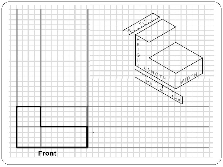
Creating your 1 st Orthographic Drawing Step 1: Draw the front view – starting in lower left corner of the paper Measure the length & height of the drawing and decide on the scale for the drawing Draw light construction lines to frame the front view then make any other relevant measurements and draw the shape using the construction lines as a guide. Color in the front, top, and side view of the diagram above
Creating your 1 st Orthographic Drawing Step 2: Prepare to draw the top and side views Draw construction lines extending upward and to the right from the front view (as shown below)
Creating your 1 st Orthographic Drawing Step 5: Verify correctness and erase construction lines
Orthographic Drawing Practice Draw a multi-view drawing of the following block: 1. 2.
Orthographic Drawing Practice Solution
Orthographic Drawing Practice Solution
Orthographic Drawing Practice Draw a multi-view drawing of the following block: 3. 4.
Orthographic Drawing Practice Solution
Orthographic Drawing Practice Solution
Orthographic Drawing Practice Draw a multi-view drawing of the following block: 5.
Orthographic Drawing Practice Solution
Dimensioning All engineering drawings should indicate dimensions - the distances and locations on the actual object Dimensions usually consist of a dimension line, capped by two arrowheads and broken in the middle for the measured distance Two extension lines may extend from the edges of the object to show clearly where the dimension line begins and ends Note: dimension and extension lines should be drawn lighter than object lines
Dimensioning
Title Blocks Title blocks are used to give essential information on technical drawings Located on the lower-right side of the engineering drawing and typically include: Name of the drafter Title of drawing Scale Date
Final Orthographic Practice Create orthographic drawings for the following blocks. Include a Title Block and dimensions. Scale is 1: 12 1” = 12”
Do Now… Complete the missing view of the object below.
Review Remember… Orthographic Drawings are drawn to scale Draw Top, Front, and Right Side as follows: Let’s review with worksheet problems.
Creating Isometric Drawings Step 1 – Draw front corner, slanting lines at 30 degrees Step 2 – Keeping the lines parallel to your initial corner sketch lines and using a ruler to maintain correct size, draw the front view shape Step 3 – Complete drawing, ensuring lines stay parallel
Another way to create isometric drawings… Step 1 – Draw front corner, slanting lines at 30 degrees Step 2 – Lightly draw an isometric box that the entire shape will fit in Step 3 – sketch details of the shape on the front, top, and side Step 4 – Erase lines that are not needed
Practice Create Isometric drawings of the following part:
Practice Create Isometric drawings of the following part:
For Homework…