Applied NWP 1 2 up until the 1960

- Slides: 26
Applied NWP • [1. 2] “…up until the 1960 s, Richardson’s model initialization problem was circumvented by using a modified set of the primitive equations…” (D&VK Chapters 6 -7) • Review LP#2 (slides #21 -end) http: //www. wmo. int/pages/publications/bulletin_en/archive/59_2_en/59_2_lynch_en. html
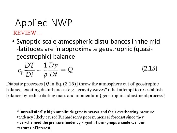
Applied NWP REVIEW… • Synoptic-scale atmospheric disturbances in the mid -latitudes are in approximate geostrophic (quasigeostrophic) balance *[unrealistically high amplitude gravity waves and their overbearing pressure tendency likely caused Richardson’s poor numerical forecast since they overwhelmed the pressure tendency signal of the synoptic-scale weather features of interest]
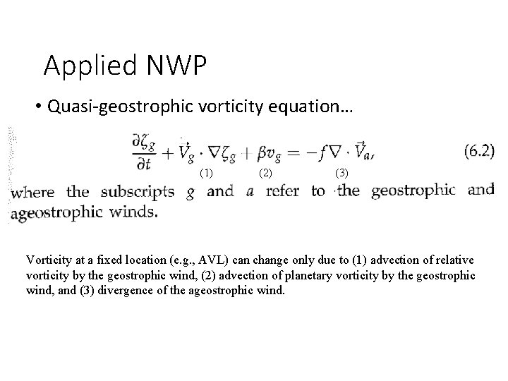
Applied NWP • Quasi-geostrophic vorticity equation… (1) (2) (3) Vorticity at a fixed location (e. g. , AVL) can change only due to (1) advection of relative vorticity by the geostrophic wind, (2) advection of planetary vorticity by the geostrophic wind, and (3) divergence of the ageostrophic wind.
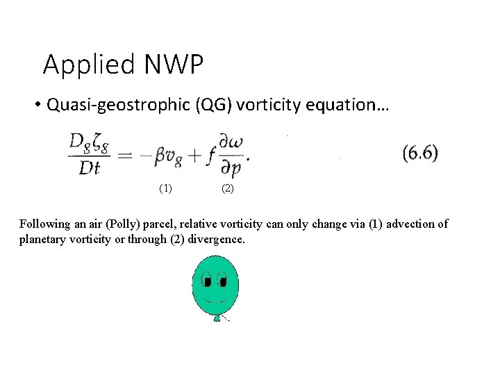
Applied NWP • Quasi-geostrophic (QG) vorticity equation… (1) (2) Following an air (Polly) parcel, relative vorticity can only change via (1) advection of planetary vorticity or through (2) divergence.
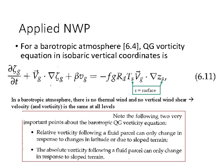
Applied NWP • For a barotropic atmosphere [6. 4], QG vorticity equation in isobaric vertical coordinates is s = surface In a barotropic atmosphere, there is no thermal wind and no vertical wind shear velocity (and vorticity) is the same at all levels
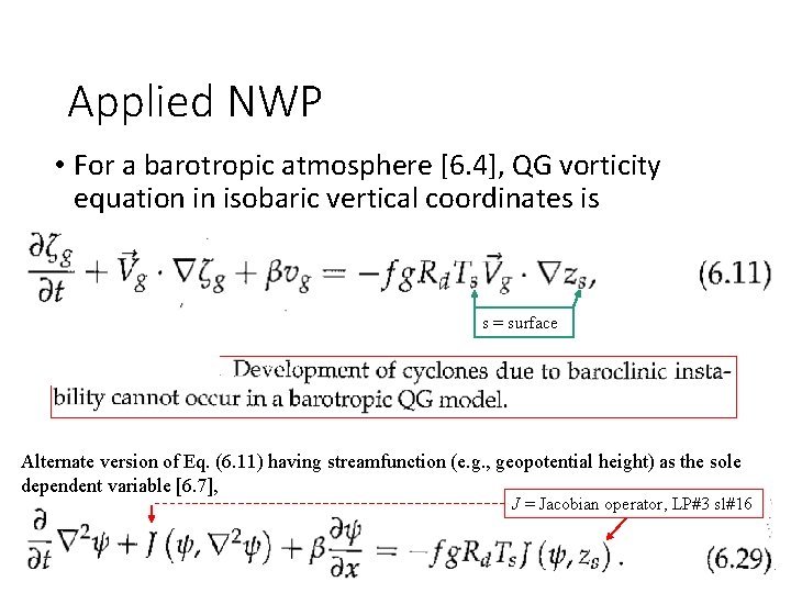
Applied NWP • For a barotropic atmosphere [6. 4], QG vorticity equation in isobaric vertical coordinates is s = surface Alternate version of Eq. (6. 11) having streamfunction (e. g. , geopotential height) as the sole dependent variable [6. 7], J = Jacobian operator, LP#3 sl#16
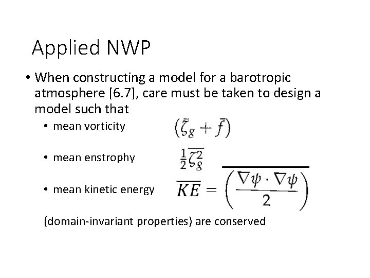
Applied NWP • When constructing a model for a barotropic atmosphere [6. 7], care must be taken to design a model such that • mean vorticity • mean enstrophy • mean kinetic energy (domain-invariant properties) are conserved
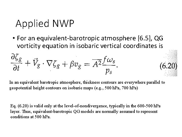
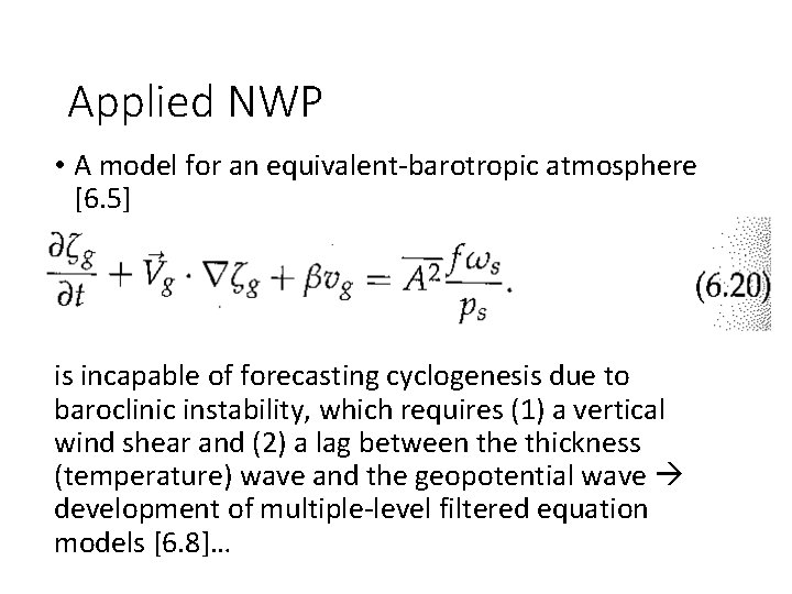
Applied NWP • For an equivalent-barotropic atmosphere [6. 5], QG vorticity equation in isobaric vertical coordinates is In an equivalent barotropic atmosphere, thickness contours are everywhere parallel to geopotential height contours on isobaric maps (e. g. , 500 h. Pa, 700 h. Pa) Eq. (6. 20) is valid only at the level-of-nondivergence, typically in the 600 -500 h. Pa layer. Thus, equivalent-barotropic QG models are normally assumed to represent conditions at 500 h. Pa.
Applied NWP • A model for an equivalent-barotropic atmosphere [6. 5] is incapable of forecasting cyclogenesis due to baroclinic instability, which requires (1) a vertical wind shear and (2) a lag between the thickness (temperature) wave and the geopotential wave development of multiple-level filtered equation models [6. 8]…
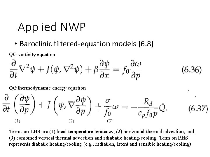
Applied NWP • Baroclinic filtered-equation models [6. 8] QG vorticity equation QG thermodynamic energy equation (1) (2) (3) Terms on LHS are (1) local temperature tendency, (2) horizontal thermal advection, and (3) combined vertical thermal advection and adiabatic heating/cooling. Term on RHS represents diabatic heating/cooling (e. g. , radiation, latent and sensible heating/cooling)
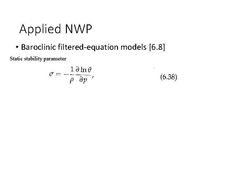
Applied NWP • Baroclinic filtered-equation models [6. 8] Static stability parameter
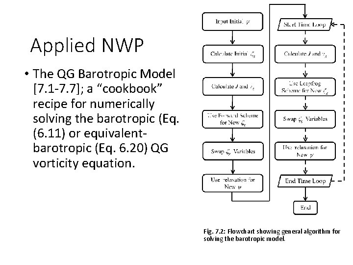
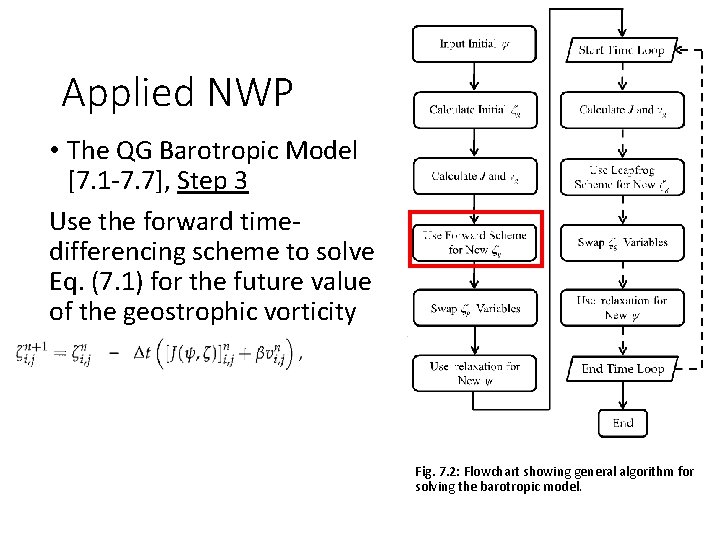
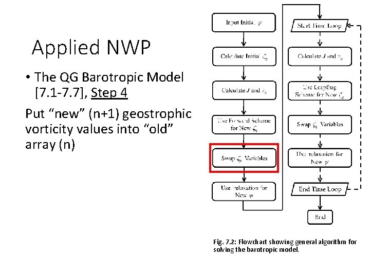
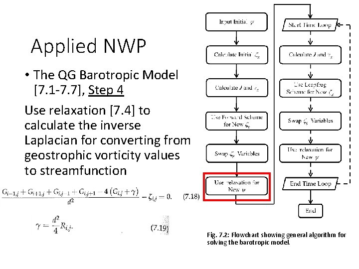
Applied NWP • The QG Barotropic Model [7. 1 -7. 7]; a “cookbook” recipe for numerically solving the barotropic (Eq. (6. 11) or equivalentbarotropic (Eq. 6. 20) QG vorticity equation. Fig. 7. 2: Flowchart showing general algorithm for solving the barotropic model.
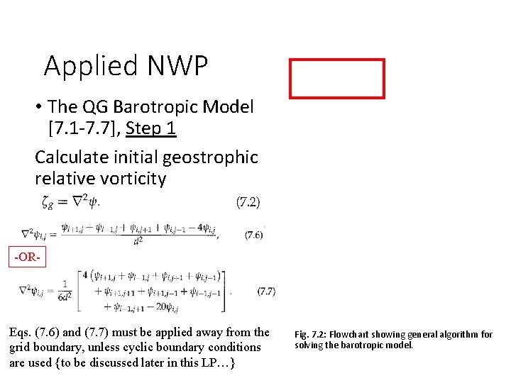
Applied NWP • The QG Barotropic Model [7. 1 -7. 7], Step 1 Calculate initial geostrophic relative vorticity -OR- Eqs. (7. 6) and (7. 7) must be applied away from the grid boundary, unless cyclic boundary conditions are used {to be discussed later in this LP…} Fig. 7. 2: Flowchart showing general algorithm for solving the barotropic model.
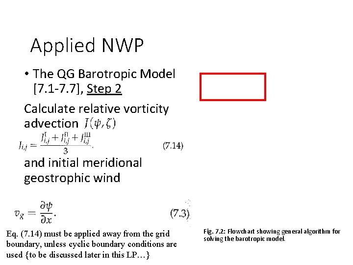
Applied NWP • The QG Barotropic Model [7. 1 -7. 7], Step 2 Calculate relative vorticity advection and initial meridional geostrophic wind Eq. (7. 14) must be applied away from the grid boundary, unless cyclic boundary conditions are used {to be discussed later in this LP…} Fig. 7. 2: Flowchart showing general algorithm for solving the barotropic model.
Applied NWP • The QG Barotropic Model [7. 1 -7. 7], Step 3 Use the forward timedifferencing scheme to solve Eq. (7. 1) for the future value of the geostrophic vorticity Fig. 7. 2: Flowchart showing general algorithm for solving the barotropic model.
Applied NWP • The QG Barotropic Model [7. 1 -7. 7], Step 4 Put “new” (n+1) geostrophic vorticity values into “old” array (n) Fig. 7. 2: Flowchart showing general algorithm for solving the barotropic model.
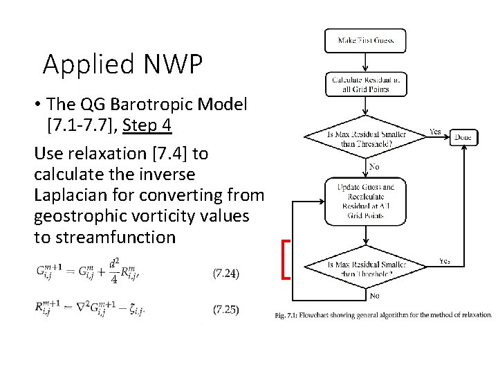
Applied NWP • The QG Barotropic Model [7. 1 -7. 7], Step 4 Use relaxation [7. 4] to calculate the inverse Laplacian for converting from geostrophic vorticity values to streamfunction Fig. 7. 2: Flowchart showing general algorithm for solving the barotropic model.
Applied NWP • The QG Barotropic Model [7. 1 -7. 7], Step 4 Use relaxation [7. 4] to calculate the inverse Laplacian for converting from geostrophic vorticity values to streamfunction
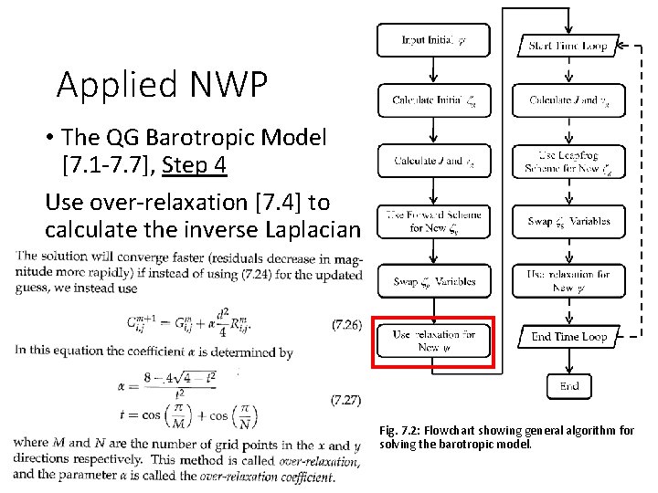
Applied NWP • The QG Barotropic Model [7. 1 -7. 7], Step 4 Use over-relaxation [7. 4] to calculate the inverse Laplacian Fig. 7. 2: Flowchart showing general algorithm for solving the barotropic model.
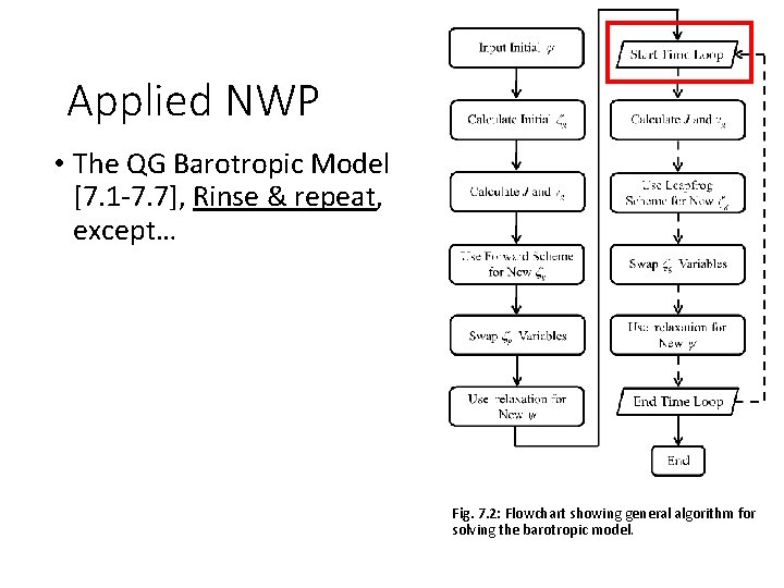
Applied NWP • The QG Barotropic Model [7. 1 -7. 7], Rinse & repeat, except… Fig. 7. 2: Flowchart showing general algorithm for solving the barotropic model.
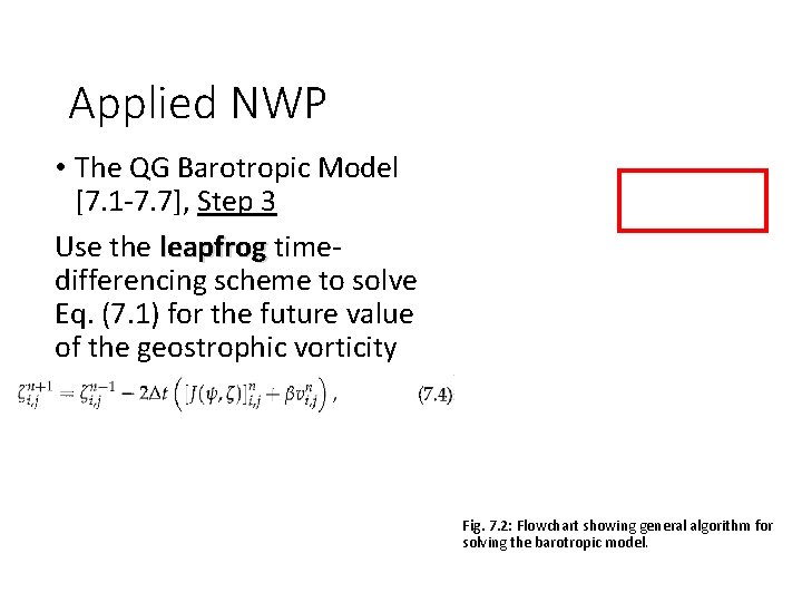
Applied NWP • The QG Barotropic Model [7. 1 -7. 7], Step 3 Use the leapfrog timedifferencing scheme to solve Eq. (7. 1) for the future value of the geostrophic vorticity Fig. 7. 2: Flowchart showing general algorithm for solving the barotropic model.
Applied NWP • The QG Barotropic Model [7. 1 -7. 7], Step 4 Put “old” (n) geostrophic vorticity values into “old old” array (n-1) Put “new” (n+1) geostrophic vorticity values into “old” array (n) Fig. 7. 2: Flowchart showing general algorithm for solving the barotropic model.
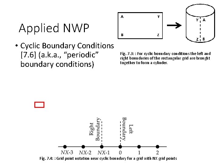
Applied NWP • Cyclic Boundary Conditions [7. 6] (a. k. a. , “periodic” boundary conditions) Fig. 7. 3: : For cyclic boundary conditions the left and right boundaries of the rectangular grid are brought together to form a cylinder. Fig. 7. 4: : Grid point notation near cyclic boundary for a grid with NX grid points
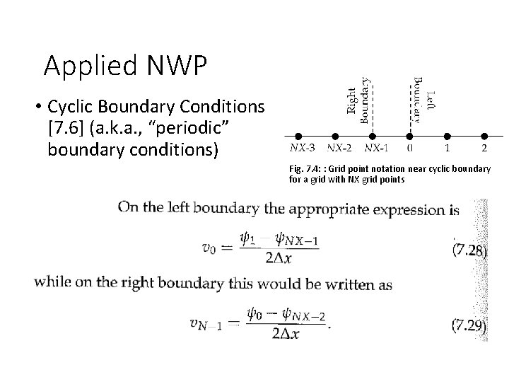
Applied NWP • Cyclic Boundary Conditions [7. 6] (a. k. a. , “periodic” boundary conditions) Fig. 7. 4: : Grid point notation near cyclic boundary for a grid with NX grid points
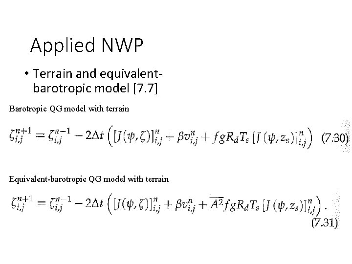
Applied NWP • Terrain and equivalentbarotropic model [7. 7] Barotropic QG model with terrain Equivalent-barotropic QG model with terrain
Applied NWP • And now for another activity… http: //psc. apl. washington. edu/HLD/ • Activity- code word- Barodancetroupe