12 Stresses in a Soil Mass INTRODUCTION 8


 8 Both body stresses and induced stresses must be taken into")


 coordinates.")
")


 (+)")


 A B D C D I")
 Influence Chart 8 Newmark (1942) constructed an influence chart based on the")
 obtained from Eq. (*) for various pressure ratios")
 values corresponding to (Note:")


- Slides: 61
12. Stresses in a Soil Mass
INTRODUCTION 8 At a point within a soil mass, stress will be developed as a result of: The soil laying above the point (overburden) by a any structural or other loading imposed on that soil mass. 8 Common examples of the external loads are as follows: Uniform strip loads such as the load on along wall footing of sufficient width. Uniformly loaded square, rectangular or circular footings such as column footings of buildings, pier footings, footings for water tanks, mats, etc Triangular and or trapezoidal strip loads such as the loads of long earth embankments.
INTRODUCTION (Cont. ) 8 Both body stresses and induced stresses must be taken into consideration in solving certain problems. 8 The focus of this chapter is on the discussion of the principles of estimation of vertical stress increase in soil due to various types of loading, based on the THEORY OF ELASTICITY. 8 We actually know that the soil is not elastic, however we use elasticity theory on the absence of better alternative. Estimation of induced vertical stress based on the assumption of elasticity yields fairly good results for practical work. 8 In the preceding chapter we discussed the stresses originated from weight of the soil itself. These stresses are called BODY STRESSES or GEOSTATIC STRESSES, or OVERBURDEN.
I. Stresses from Approximate Methods a. 2: 1 Method 8 In this method it is assumed that the STRESSED AREA is larger than the corresponding dimension of the loaded area by an amount equal to the depth of P the subsurface area. 8 Therefore, if a load is applied on a rectangular with dimension B and L, the stress on the soil at depth z is considered to be uniformly distributed on an area with dimension (B+z) and (L+z). B z 2 1 B+z 8 This is called 2: 1 method because the stressed area increases at a slope of 1 horizontally for each 2 of depth as measured from the depth of foundation.
P L z B L+z B+z b. Thirty-Degree Method 8 Here the stressed area extends outward from the edges of a foundation at a 30 o angle from vertical as shown below. P B z 30 o B+2 ztan 30
Remarks 8 In both methods, the stress at a given depth is uniform over the stressed area. In reality, however, stress directly beneath the foundation will be higher than beneath edges. 8 Hence approximate methods underestimate stress directly beneath the foundation and overestimate it as we go toward the edges. They are only good for preliminary analysis. 8 Approximate method are good only for finite loaded area (logically).
8 If the load at the surface is given to be distributed, it is first converted to point load by multiplying by the area (B x L) as demonstrated in the figure below.
II. Stresses From Theory of Elasticity 8 There a number of solutions which are based on theory of elasticity. Most of them assume the following assumptions: The soil is homogeneous The soil is isotropic The soil is perfectly elastic infinite or semi-finite medium 8 The derivations of the equations for various common loadings are tedious. 8 We will concentrate only on formula, tables and charts for some of the loadings most commonly encountered in practice. 8 Tens of solutions for different problems are now available in the literature. It is enough to say that a whole book (Poulos and Davis) is now available for the elastic solutions of various problems.
The book contains a comprehensive collection of graphs, tables and explicit solutions of problems in elasticity relevant to soil and rock mechanics.
8 The available solution depends on the following conditions: 1. Types of the applied load Point Distributed 2. Shape of the loaded area Rectangular Square Circular etc. 3. Extension of the Medium Half-space Finite layered 4. Type of soil Cohesive Cohesionless 5. Location of Load At the surface At a certain depth 6. Stiffness of Loaded Area Flexible Rigid 8 We can see that a lot of combinations can be made from the above conditions. Next we will consider some of these solutions which are well-known and has been accepted and extensively used.
Cases that we will consider: q Vertical stress due to a vertical point load q Vertical stress due to a vertical line load q Vertical stress due to a vertical strip load q Vertical stress under the Corners of triangular load of finite length q Vertical stress due to embankment load q Vertical stress below a center of a uniformly loaded Circular area q Vertical stress at any point below a uniformly loaded Circular area q Vertical stress below the corner of a uniformly loaded rectangular area
1. Vertical Stress Caused by a Vertical Point Load 8 The most important original solution was given by BOUSSINESQ (1885) for the distribution of stress within a linear elastic half space resulting from a point load normal to the surface as shown
2. Vertical Stress Caused by a Vertical Line Load 8 The vertical stress increase inside the soil caused by a vertical flexible line load of finite length that has an intensity q/unit length on the surface of a semi-infinite soil mass is given by:
8 We can use either polar or rectangular (Cartesian) coordinates.
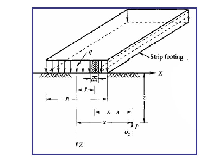
3. Vertical Stress Caused by a Vertical Strip Load (Finite width and infinite length) Such conditions are found for structures extended very much in one direction, such as strip and wall foundations, foundations of retaining walls, embankments, dams and the like.
4. Vertical Stress Under the Corners of Triangular Load of Finite Length m = L/z n = B/z O Q Value of n Beneath Corner, O Beneath Corner, Q Value of m
5. Vertical Stress Due to Embankment Loading
b/z a/z
EXAMPLE 1 A 3 m high embankment is to be constructed as shown below. If the unit weight of soil used in the embankment is 19. 0 k. N/m 2, calculate the vertical stress due to the embankment loading at points P 1, P 2, and P 3.
Vertical stress due to the embankment loading at points P 1
Vertical stress due to the embankment loading at points P 2 (-) (+)
Vertical stress due to the embankment loading at points P 3
Solution The embankment is divided into blocks as shown in the figure for making use of the graph. The calculations are arranged as follows:
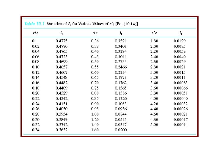
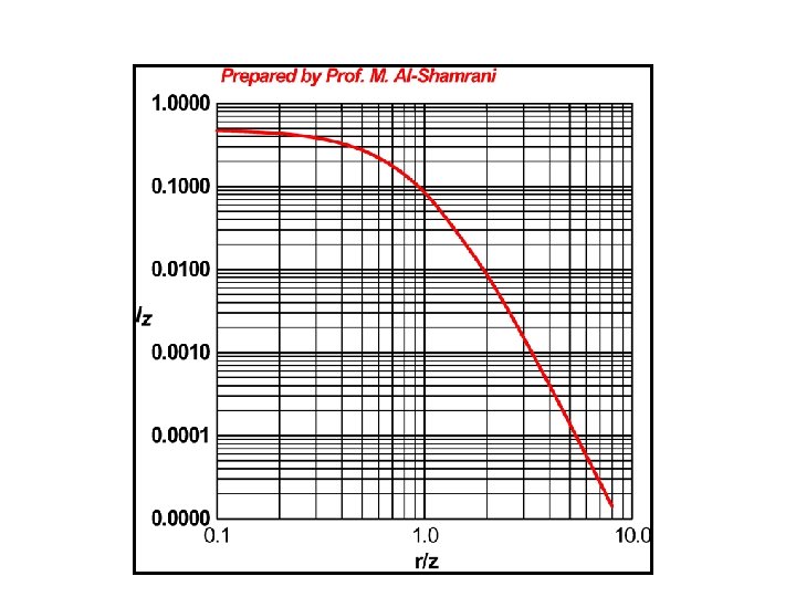
6. Vertical Stress Below the Center of a Uniformly Loaded Circular Area Using Boussinesq’s solution for vertical stress sz caused by a point load one also can develop an expression for the vertical stress below the center of a uniformly loaded flexible circular area.
7. Vertical Stress At any Point Below a Uniformly Loaded Circular Area z x
EXAMPLE 2 Circular tank, 25 m diameter with bearing pressure P = 122 k. Pa. Find stress induced by the tank 10 m below the edge. solution:
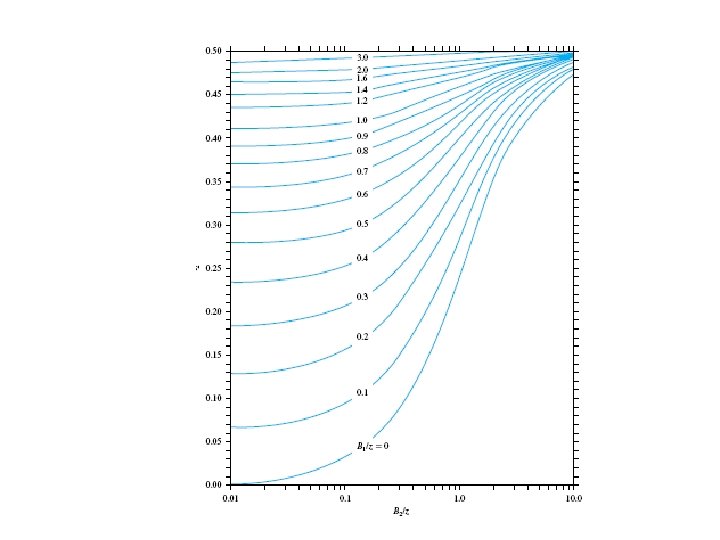
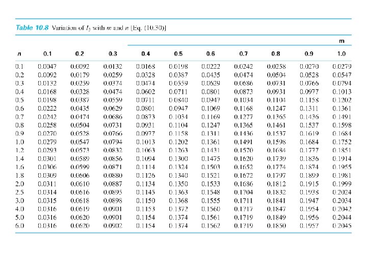
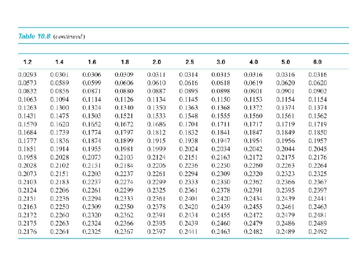
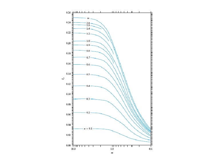
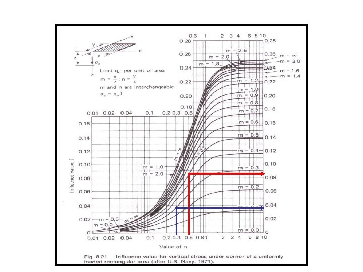
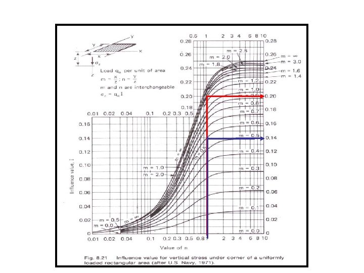
8. Vertical Stress Below the Corner of a Uniformly Loaded Rectangular Area I 3 is a dimensionless factor and represents the influence of a surcharge covering a rectangular area on the vertical stress at a point located at a depth z below one of its corner.
Value of m Value of n
EXAMPLE 2 Determine the increase in stress at point A and A/ below the footing shown below. Solution
EXAMPLE 3 For the flexible footing shown below, determine the increase in the vertical stress at depth of z = 5 below point C for the uniformly distributed surface load q. Solution
Some Possible Cases Case I A I 3(1) A B D C D I 3=4 I 3(1) A D Note: Loaded area: ABCD Case II I 3(3) I 3(1) I 3(4) I 3(2) B C I 3=I 3(1)+I 3(2)+I 3(3)+I 3(4) Case IV B C Case III A B E D C F I 3=I 3(AEFD)- I 3(BEFC) E K I 3=I 3(AEFH) - I 3(BEFG) –I 3(DKFH)+I 3(CKFG) H G F
Newmark’s (1942) Influence Chart 8 Newmark (1942) constructed an influence chart based on the Boussinesq’s solution. 8 This chart can be used to determine the vertical stress at any point below uniformly loaded flexible area of any shape. Development of the chart (*)
8 Using the value of (R/z) obtained from Eq. (*) for various pressure ratios (i. e /q), Newmark (1942) presented an influence chart that can be used to determine the vertical pressure at any point below a uniformly loaded flexible area of any shape.
8 The radii of the circles are equal to (R/z) values corresponding to (Note: For sz/q = 0, R/z = 0, and for sz/q = 1, R/z = , so nine circles are shown. ) 8 The unit length for plotting the circle is 8 The circles are divided by equally spaced radial lines 8 The influence value of the chart is given by 1/N, where N is equal to the number of elements in the chart. 8 In the shown chart, there are 200 elements; hence the influence value is 0. 005.
Procedures for Using the Chart
EXAMPLE 4 3 m 25 mm
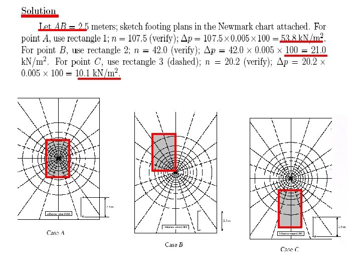
EXAMPLE 5 A rectangular footing is 3 m X 5 m and transmits a uniform load of 100 k. Pa into the soil mass. Compute the incremental vertical pressures at: 8 Point A which is directly below the center of the footing 8 Point B Below the corner of the footing 8 Point C which is along the longest axis of the footing offset by 1. 5 m from the nearest edge. All points are 2. 5 m deep relative to the footing base.
EXAMPLE 6 A raft foundation of the size given below carries a uniformly distributed load of 300 k. N/m 3. Estimate the vertical pressure at a depth 9 m below the point O marked in the figure.
Approach 1: Using the Principle of Superposition Recall: Loaded area is ACDLGH Area KABO m n I 3 1. 33 1 0. 197 BCEO 1 0. 66 0. 145 KHFO 1. 33 0. 83 0. 175 MDEO 0. 67 0. 33 0. 075 NGFO 0. 83 0. 33 0. 085 NLMO 0. 33 0. 045 B A K C M L E N H D G F I =0. 197 +. 145 +. 175 -. 085 -. 046 = 0. 312
Approach 2: Using Newmark’s chart • • • The Depth at which required is 9 m From the Fig. across, the scale of the foundation plan is AB = 3 cm = 9 m or 1 cm = 3 m. Plot the loaded area at this scale. Superimpose the plan on the chart with point O coinciding with the center of the chart. Number of loaded blocks occupied by the plan, M = 62 The vertical stress is given by: O
N = 50 IV =. 02
9. Total stress with a surface surcharge load If the surcharge loading is extensively wide, the increase in vertical total stress below it may be considered constant with depth and equal to the magnitude of the surcharge.
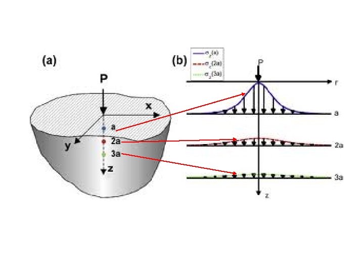
Pressure Bulb, isobar 8 When a load is applied to the soil surface, it increases the vertical and lateral stresses within the soil mass. 8 The increased stresses are greatest directly under the loaded area and DISSIPATE within the soil mass as a function of distance away from the loaded area. 8 This is commonly called spatial attenuation of applied loads. 8 An isobar is a curve that connects all points below the ground surface of equal stress. 8 Isobars are also called stress contours, or bulbs of pressure or simply pressure bulbs. 8 A system of isobars indicates the spatial variation of stress intensity.
Pressure Bulb for Point Load
8 The relationships for can be used to calculate the stress increase at various grid points below the loaded area. Based on those calculated stress increases, stress isobars can be plotted. Strip Footing Square Footing Circular Footing
Conceptual Illustration The figure below shows how the load is distributed if a single thickness of balls is loaded in a two dimensional analysis. In fact, the soil is three-dimensional, not two, and the load is distributed over an even greater number of balls at each layer.
8 A schematic of the vertical stress distribution with depth along the centerline under an embankment of height, h, constructed with a soil having a total unit weight, g, is shown in the figure below.
Influence Depth Influence depth will depend on the intensity of the applied pressure and the size of the loaded area.
Vertical Stress - Horizontal Distribution
OVERLAPPING OF STRESSES Three parallel strip footings 3 m wide each and 5 m apart center to center transmit contact pressures of 200 , 150 and 100 k. N/m 2, respectively. Calculate the vertical stress due to the combined loads beneath the centers of each footing at a depth of 3 m below the base.