Mechanics of MaterialsME294 Lecture 7 Principal Stresses and
 Lecture 7: Principal Stresses and Strains (chapter 7 of R. S.")

arising in bars subject to")


- Slides: 24
Mechanics of Materials(ME-294) Lecture 7: Principal Stresses and Strains (chapter 7 of R. S. Khurmi)
Introduction • Transformations of Stress and Strain ( chapter 7 of Mechanics Of Materials 6 TH Edition, by Ferdinand P. Beer , E. Russell Johnston, Jr. John T. Dewolf, David F. Mazurek) • Combined Stress (chapter 3 Strength Of Materials Fifth Edition by William A. Nash, C. Potter, Schaum’s Outline Series) • Principal Stresses and Strains (chapter 7 of R. S. Khurmi)
Introduction We have studies ▫ Normal/Direct Stresses (Tensile and Compressive)arising in bars subject to axial loading � 1 -D (In one direction) � 3 -D ▫ as well as shearing stresses • But frequently bars are simultaneously subject to several kinds of loadings, and it is required to determine the state of stress under these conditions. • It is the purpose of this chapter to investigate the state of stress on an arbitrary plane through an element in a body subject to both normal and shearing stresses. • There are two methods to find the state of stress. ▫ Analytical ▫ Graphical
Stress Elements • The most useful way of representing the stresses is to isolate a small element of material, such as the element labeled C in Fig( c) , and then show the stresses acting on all faces of this element. • An element of this kind is called a stress element. The stress element at point C is a small rectangular block (it doesn’t matter whether it is a cube or a rectangular parallelepiped) with its right-hand face lying in cross section mn.
• The dimensions of a stress element are assumed to be infinitesimally small, but for clarity we draw the element to a large scale, as in Fig. a. • In this case, the edges of the element are parallel to the x, y, and z axes, and the only stresses are the normal stresses σx acting on the x faces (recall that the x faces have their normals parallel to the x axis). • Because it is more convenient, we usually draw a two-dimensional view of the element (Fig. b) instead of a three-dimensional view.
Stresses on Inclined Sections • Larger stresses may occur on inclined sections. Therefore, we will begin our analysis of stresses and strains by discussing methods for finding the normal and shear stresses acting on inclined sections cut through a member • To obtain a more complete picture, we need to investigate the stresses acting on inclined sections, such as the section cut by the inclined plane pq in Fig. a.
Stresses on Inclined Sections • Because the stresses are the same throughout the entire bar, the stresses acting over the inclined section must be uniformly distributed, as pictured in the free body diagrams of Fig. b (threedimensional view) and Fig. c (two-dimensional view). • From the equilibrium of the free body we know that the resultant of the stresses must be a horizontal force P. • The resultant is drawn with a dashed line in Figs. b and c.
Let us now return to the task of finding the stresses acting on section pq. As already mentioned, the resultant of these stresses is a force P acting in the x-direction. • This resultant may be resolved into two components, a normal force N that is perpendicular to the inclined plane pq and a shear force V that is tangential to it. • These force components are N =P cosθ V =P sinθ
• Associated with the forces N and V are normal and shear stresses that are uniformly distributed over the inclined section (Figs. c and d). • The normal stress is equal to the normal force N divided by the area of the section, and the shear stress is equal to the shear force V divided by the area of the section. Thus, the stresses are
Sign convention for stresses acting on an inclined section. (Normal stresses are positive when in tension and shear stresses are positive when they tend to produce counterclockwise rotation. ) For a bar in tension, the normal force N produces positive normal stresses σθ and the shear force V produces negative shear stresses τθ. These stresses are given by the following equations :
Following expressions for the normal and shear stresses These equations give the stresses acting on an inclined section oriented at an angle u to the x axis. It is important to recognize that above Eqs. were derived only from statics, and therefore they are independent of the material. Thus, these equations are valid for any material, whether it behaves linearly or nonlinearly, elastically or inelastically.
Maximum Normal and Shear Stresses The maximum normal stress occurs at θ = 0 and is The shear stress τ is zero on cross sections of the bar (θ =0) as well as on longitudinal sections (θ =90°). Between these extremes, the stress varies as shown on the graph, reaching the largest positive value when θ= 45° and the largest negative value when θ =-45°. These maximum shear stresses have the same magnitude
• Even though the maximum shear stress in an axially loaded bar is only one-half the maximum normal stress, the shear stress may cause failure if the material is much weaker in shear than in tension. • An example of a shear failure is pictured in Fig. , which shows a block of wood that was loaded in compression and failed by shearing along a 45° plane. • A similar type of behavior occurs in mild steel loaded in tension
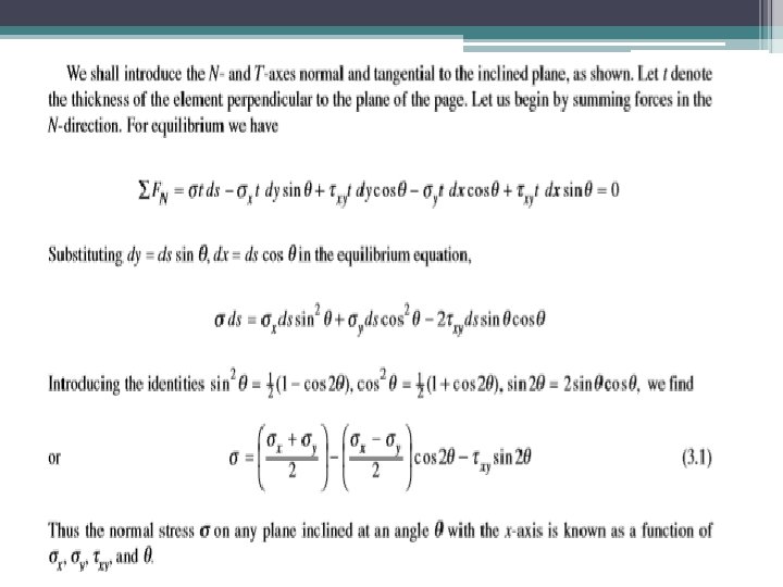
General Case of Plane Stress • In general if a plane element is removed from a body it will be subject to the normal stresses σx and σy together with the shearing stress τxy , as shown in Fig. 3 -1. We assume that no stresses act on the element in the z-direction. For normal stresses, tensile stress is considered to be positive, compressive stress negative. For shearing stresses, the positive sense* is that illustrated in Fig. 3 -1.
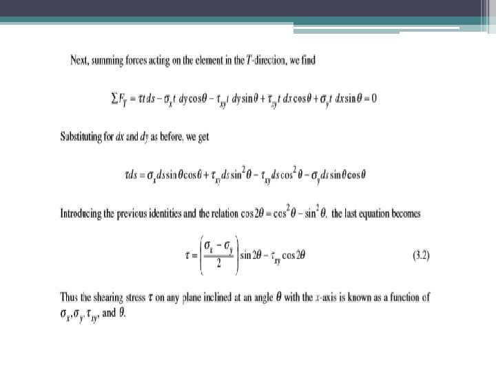
If moments are taken about the center of the face shown, we would see that τxy = τyx since the normal stresses pass through the center. We shall assume that the stresses σx , σy and τxy are known. Frequently it is desirable to investigate the state of stress on a plane inclined at an angle θ, measured counterclockwise to the x -axis, as shown in Fig. 3 -1. The normal and shearing stresses on such a plane are denoted by σ and τ and appear as in Fig. 3 -2.
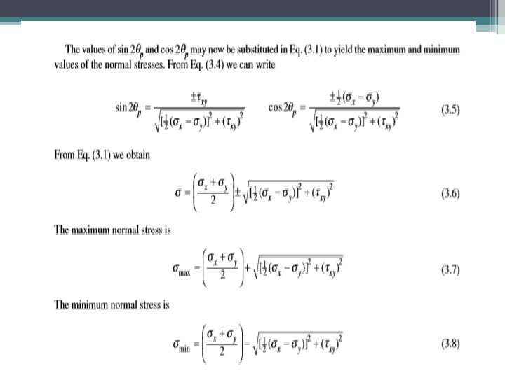
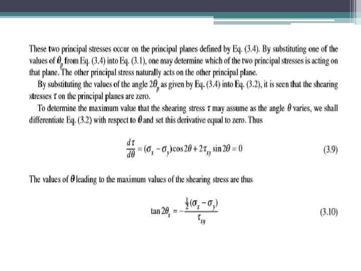
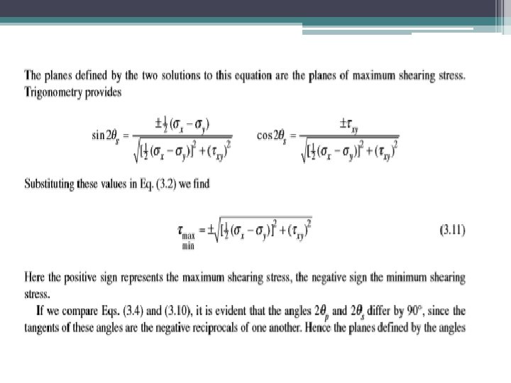
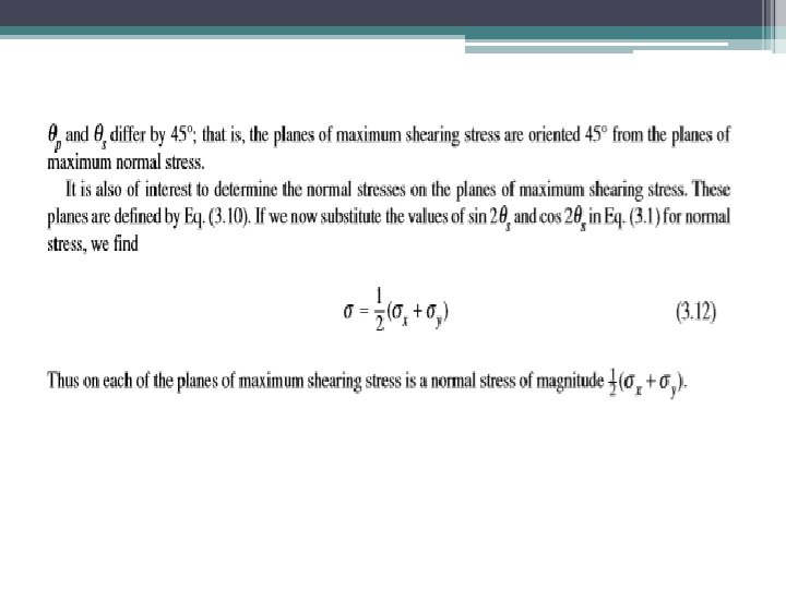
Principal Stresses and Maximum Shearing Stress
Mohr’s Circle-Graphical Form • All the information contained in the above equations may be presented in a convenient graphical form known as Mohr’s circle. • In this representation normal stresses are plotted along the horizontal axis and shearing stresses along the vertical axis. • The stresses σx, σy, and τxy are plotted and a circle is drawn through these points having its center on the horizontal axis.
Mohr’s Circle Figure 3 -3 shows Mohr’s circle for an element subject to the general case of plane stress, shown in Fig. 3 -1. The ends of diameter BCD are the points (σy, τyx) at B and (σx, –τxy) at D. The center C is at [(σx + σy)/2, 0)]. , , and For applications see Problems 3. 4, 3. 5, 3. 6, 3. 7, 3. 9, and 3. 11. of Strength Of Materials Fifth Edition