Useful Terminology Colorimetry is the use of the


- Slides: 33


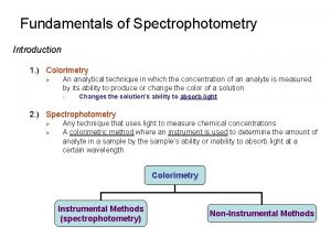
Useful Terminology ØColorimetry is the use of the human eye to determine the concentration of colored species. ØSpectrophotometry is the use of instruments to make the same measurements. It extends the range of possible measurements beyond those that can be determined by the eye alone. Note: This experiment will demonstrate both techniques on the same set of dyes.

Colorimetry ØVisual Observations – Because colorimetry is based on inspection of materials with the human eye, it is necessary to review aspects of visible light. ØVisible light is the narrow range of electromagnetic waves with the wavelength of 400 -700 nm. ROY G. BIV= the mnemonic used to remember the colors of the visible spectrum.

Visible light is only a very small portion of the electromagnetic spectrum. Note: Frequency (υ) and Energy (E) are directly proportional whereas Frequency (υ) and Wavelength (λ) are inversely proportional.

Electromagnetic Spectrum Type of Radiation Frequency Range (Hz) Wavelength Range Type of Transition gamma-rays 1020 -1024 <1 pm nuclear X-rays 1017 -1020 1 nm-1 pm inner electron ultraviolet 1015 -1017 400 nm-1 nm outer electron visible 4 -7. 5 x 10¹⁴ 750 nm-400 nm outer electron near-infrared 1 x 10¹⁴ -4 x 10¹⁴ 2. 5 µm-750 nm outer electron molecular vibrations infrared 1013 -1014 25 µm-2. 5 µm molecular vibrations microwaves 3 x 10¹¹ -1013 1 mm-25 µm molecular rotations, electron spin flips* radio waves <3 x 10¹¹ >1 mm nuclear spin flips*

Electromagnetic radiation is characterized by its wavelength, , Frequency, and energy, E: E = hc / c= Where h = Planck’s constant & c = speed of light in a vacuum. (a) longer wavelength, lower energy; (b) shorter wavelength, higher energy.

Color Wheel (ROYGBIV) Complementary colors lie across the diameter on the color wheel and combine to form “white light”, so the color of a compound seen by the eye is the complement of the color of light absorbed by a colored compound; thus it completes the color.

Observed Color of Compound Color of Light Absorbed Approximate Wavelength of Light Absorbed Green 700 nm Blue-green 600 nm Violet 550 nm Red-violet 530 nm Red 500 nm Orange 450 nm Yellow 400 nm

Observed Color of Compound Color of Light Absorbed Approximate Wavelength of Light Absorbed Green Red 700 nm Blue-green Orange-red 600 nm Violet Yellow 550 nm Red-violet Green-yellow 530 nm Red Green 500 nm Orange Blue 450 nm Yellow Violet 400 nm

Visual Colorimetry Intensity: For light shining through a colored solution, the observed intensity of the color is found to be dependent on both the thickness of the absorbing layer (pathlength) and the concentration of the colored species. ←Side view ←Top view (a. k. a. Bird’s eye view) For One Color: A series of solutions of a single color demonstrates the effect of either concentration or pathlength, depending on how it is viewed.

Visual Colorimetry ←Ratio used ←Purple produced For more than one color: the ratio of an unknown mixture can also be determined by matching the shade of the color to those produced from known ratios. In this example, the ratio of a mixture of red and blue can be determined visibly by comparing the mixture to purples produced from known ratios of red and blue.

Dilution Factor (constant pathlength) Recall: C 1 V 1= C 2 V 2 Then for the dilution, Cdiluted x Vdiluted= Cstd x Vstd Cdiluted = Cstd x (Vstd / Vdiluted) Since Vdiluted = Vtotal Cdiluted = Cstd x (Vstd / Vtotal) Substituting the volumes: Cdiluted = Cstd x (3 drops / 8 drops) If the original concentration is 5. 88 ppm, then: 3 drops of dye std C diluted = 5. 88 ppm x (3 / 8) + 5 drops water 8 drops total volume C diluted = 2. 21 ppm

Intensity: When the product of the concentration and the pathlength of any two solutions of a colored compound are the same, then the same intensity or darkness of color is observed. Duboscq visual colorimeter Adjustable Path Lengths

Spectrophotometry ØSpectrophotometer - an instrument that measures the amount of light absorbed, or the intensity of color at a given wavelength. ØThe intensity of color can be given a numerical value by comparing the amount of light prior to passing it through the sample and after passing through the sample. ØThese quantitative measurements of light absorbed are the Transmittance and the Absorbance.

Absorbance Beer-Lambert Law (a. k. a. Beer's law) - the linear relationship between absorbance and concentration of an absorbing species. A = abc A is the absorbance “a” is molar absorptivity in L/[(mole)(cm)] Also called “extinction coefficient” or “ ”; it is dependent on the material being studied. “b” is the path length in cm The diameter of the cuvette or sample holder which is the distance the light travels through the absorbing sample. “b” is a constant when the same size cuvette is used for all samples. “c” is the concentration of the sample in (mol/L) Main use of Beer’s Law is to determine the concentration of various solutions. (We used Beer’s Law to calculate concentration in the equilibrium experiment. )

Transmittance is Related to Absorbance Transmittance is given by the equation: T = I/Io where I is the intensity of the light after it has gone through the sample & I 0 is the initial (time = 0) light intensity. Absorbance is related to the %T: A = -log. T = -log(I/ Io)

Equation Summary T= (I/I 0) = 10 -A %T = (I/I 0) x 100 A = -log. T = log(1/T) Sample Calculation If %T = 95%, then A = log(100/95) = log(1/. 95) = -log(. 95) A = 0. 02227 Note the scale for Absorbance: 9/10 th of the scale is from 0 -1 and 1/10 th is from 1 -2. For this reason, the spectrometers have been calibrated in % Transmittance and all readings will be taken in %Transmittance.

Spectronic 20 (a. k. a. Spec-20) Ø Spec-20 - A single-beam visible light spectrophotometer. Ø Tungsten filament lamp emits visible wavelengths of light. Ø Blank is inserted to adjust 100%Transmittance at each wavelength.

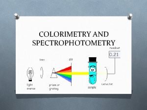
Simple Spectrophotometer Schematic ØThe lamp emits all colors of light (i. e. , white light). ØThe monochromator selects one wavelength and that wavelength is sent through the sample. ØThe detector detects the wavelength of light that has passed through the sample. ØThe amplifier increases the signal so that it is easier to read against the background noise.

Spectronic 20 Instructions (Directions below will be available next to each instrument) Sample Chamber Digital Display Mode Knob (set to Trans) 1. With sample chamber empty, set desired wavelength then adjust to 0%T with right knob on front panel. 2. Insert blank solution, close lid and adjust 100%T with right knob on front panel. 3. Insert dye solutions, read and record %T values. 4. Change wavelength*, repeat steps 2 -4. Filter Lever 0 -100%T Knob Wavelength Knob *NOTE: The filter must be changed periodically to coordinate with the wavelength range studied: blue (400 -449), green (450 -549) and orange (550 -749).

Post Lab: 4 Plots of Absorption Data Plots similar to the 3 below will need to be generated using a computer program such as Excel. You will also need to make a plot of your unknown blue or red which will look similar to #1 or #2. #1 #2 #3 This plot is shown here simply to demonstrate the underlying colors of the purple graph.

Development of the Spectroscope Joseph von Fraunhofer’s initial desire was to create a glass lens that did not produce an image that was fringed with a rainbow of colors. He realized the problem was that the glass lens bent some colors more than others. He began searching for a source of light of a single color. Joseph von Fraunhofer (March 6, 1787 – June 7, 1826) In 1814, he developed a spectroscope to study the spectrum of the light given off by the sun. He was amazed to discover that in the midst of the rainbow of colors was a series of black lines. These dark lines were later determined to be the result of the absorption of selected frequencies of the electromagnetic radiation by an atom or a molecule.

Fraunhofer lines observable in the Solar Spectrum 390 nm 700 nm

Development of Diffraction Gratings Fraunhofer also completed an important theoretical work on diffraction and established the laws of diffraction. One important innovation that Fraunhofer made was to place a diffraction slit in front of the objective of a measuring telescope in order to study the solar spectrum. He later made and used diffraction gratings with up to 10, 000 parallel lines per inch. By means of these gratings he was able to measure the minute wavelengths of the different colors of light. (Diffraction gratings will be discussed more later. )

1855 -1860 - Gustav Kirchhoff and Robert Bunsen Gustav Robert Kirchhoff Robert Wilhelm Eberhard Bunsen (March 12, 1824 – October 17, 1887) German Physicist (March 31, 1811 – August 16, 1899) German Chemist Bunsen and Kirchhoff further developed the spectroscope by incorporating the Bunsen burner as a source to heat the elements. In 1861, experiments by Kirchhoff and Bunsen demonstrated that each element, when heated to incandescence, gave off a characteristic color of light. When the light was separated into its constituent wavelengths by a prism, each element displayed a unique pattern or emission spectrum.

Emission Spectra Complement Absorption Spectra The emission spectrum seemed to be the complement to the mysterious dark lines (Fraunhofer lines) in the sun's spectrum. This meant that it was now possible to identify the chemical composition of distant objects like the sun and other stars. They concluded that the Fraunhofer lines in the solar spectrum were due to the absorption of light by the atoms of various elements in the sun's atmosphere.

Hydrogen Spectrum – The Balmer Series In 1885, Johann Jakob Balmer analyzed the hydrogen spectrum and found that hydrogen emitted four bands of light within the visible spectrum. His empirical formula for the visible spectral lines of the hydrogen atom was later found to be a special case of the Rydberg formula, devised by Johannes Rydberg. Johann Jakob Balmer (May 1, 1825 – March 12, 1898) Swiss Mathematician & Honorary Physicist Wavelength (nm) Color 656. 2 red 486. 1 blue 434. 0 blue-violet 410. 1 violet

Part A: Calculating the Balmer & Lyman Series The four bands of light calculated by Balmer can be simply calculated using the Rydberg equation: =c/ Where v = frequency n = the quantum number R = (Rydberg constant) R = 3. 29 1015 Hz 1 Hz = 1 s-1 C = (speed of light) C = 2. 9979 108 m/s The permitted energy levels of a hydrogen atom. *These equations will be used on page 159.

v In 1913, Bohr developed a quantum model for the hydrogen atom. v Proposed the Solar System model of the atom where the electron in a hydrogen atom moves around the nucleus only in certain allowed circular orbits. Niels Henrik David Bohr Oct. 7, 1885 – Nov. 18, 1962 Danish Physicist The Nobel Prize in Physics 1922 for the investigation of the structure of atoms and of the radiation emanating from them. https: //www. youtube. com/watch? v=-YYBCNQn. YNM These orbits then correspond to the energy levels seen in the Balmer series. (p 167)

PART B: Emission spectrum of other compounds using The STAR Spectrophotometer. 1. View the line spectrum through the STAR Spectrophotometer - point slit towards the light and view to the right. 2. Verify that the scale is lined-up accurately by looking at the fluorescent light. In addition to other lines, you should see a green doublet for mercury at ~570 nm (the scale on the bottom). 3. Measure the line spectrum of the gas tubes set up in Room 201. Note: The fastest/easiest way to do this is have one partner view the lines and the other write down the observations. 4. Compare your results with NIST literature values. For the fluorescent light compare it to the element mercury.

Atomic Spectra of Hydrogen & the Noble Gases Hydrogen Helium Neon The Atomic Spectra will be determined for Hydrogen and the Noble Gases by looking at the gas discharge tubes.

Colorimetry & Spectrophotometry Checkout Visual Portion 1 - 12 well plate 3 - 12 well strips* 5 - Beral pipets** Spec-20 s 5 - cuvettes in a test tube rack *2 of which need to be at least 9 wells long. **Don’t have to be returned. Dyes - Located in Lab: Record Concentrations Blue std. = _____ ppm Red std. = _____ ppm Waste (We are using FDA food dyes and distilled water. ) Atomic Spectra Checkout STAR Spectroscope Set of Crayons ROYGBIV Gas discharge tubes set up in Room 201. (for viewing by STAR spectroscope)

For April 21 -23 Turn In: 1. ) Colorimetry & Spectrophotometry pp 51 -58 + 4 Graphs 2. ) Atomic Spectra pp 159 -161 & 167 -169 Read Over: “Radiochemistry” pp 119 -136 in Lab Packet & remember to bring your student id.
 Colorimetry and spectrophotometry
 Colorimetry
 Auto analyzer biochemistry
 Colorimetry
 Principle of colorimetry
 Colorimetry involve
 Fundamentals of spectrophotometry
 All household materials are useful
 Mole background
 Lane designation terminology
 The use of uniform terminology and plain english
 Sự nuôi và dạy con của hổ
 điện thế nghỉ
 Một số thể thơ truyền thống
 Nguyên nhân của sự mỏi cơ sinh 8
 Trời xanh đây là của chúng ta thể thơ
 Gấu đi như thế nào
 Thế nào là số nguyên tố
 Thiếu nhi thế giới liên hoan
 Tỉ lệ cơ thể trẻ em
 Fecboak
 Các châu lục và đại dương trên thế giới
 Thế nào là hệ số cao nhất
 Sơ đồ cơ thể người
 Tư thế ngồi viết
 Hát kết hợp bộ gõ cơ thể
 đặc điểm cơ thể của người tối cổ
 Mật thư anh em như thể tay chân
 Chụp tư thế worms-breton
 Tư thế ngồi viết
 ưu thế lai là gì
 Thẻ vin
 Bàn tay mà dây bẩn
 Thơ thất ngôn tứ tuyệt đường luật
