PCI 6 th Edition Connection Design Presentation Outline


 •")


·Aw Where: f. Vp =")
 f. Tn = f(0. 6·Fy)·a·h·t 2 Where:")

 f. Tn = 2·f(0. 6·Fy)·Ᾱ·t Where: f.")


 Design introduced • Comparison of")
 • Stress at each point calculated by mechanics of")
 • Weld Area ( Aw ) based on effective")
 • Deformation Compatibility Solution • Rotation about an Instantaneous Center")
 • Increased capacity – More weld regions achieve ultimate strength")


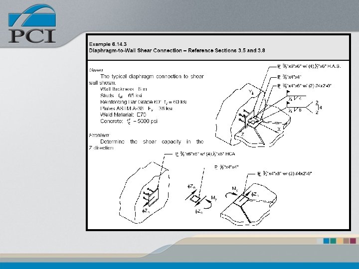
 h = 14 in d =")


 #3 ties = (4) (0. 11")
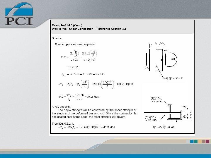
 Determination of bearing plate size")
/(80) =")


- Slides: 102
PCI 6 th Edition Connection Design
Presentation Outline • Structural Steel Design • Limit State Weld Analysis • Strut – Tie Analysis for Concrete Corbels • Anchor Bolts • Connection Examples
Changes • New method to design headed studs (Headed Concrete Anchors - HCA) • Revised welding section – Stainless Materials – Limit State procedure presented • Revised Design Aids (moved to Chapter 11) • Structural Steel Design Section – Flexure, Shear, Torsion, Combined Loading – Stiffened Beam seats • Strut – Tie methodology is introduced • Complete Connection Examples
Structural Steel Design • Focus on AISC LRFD 3 rd Edition – Flexural Strength – Shear Strength – Torsional Strength – Combined Interaction • Limit State Methods are carried through examples
Structural Steel Details • Built-up Members • Torsional Strength • Beam Seats
Steel Strength Design • Flexure f. Mp = f·Fy·Zs Where: f. Mp = Fy = Zs = Flexural Design Strength Yield Strength of Material Plastic Section Modulus
Steel Strength Design • Shear f. Vn = f(0. 6·Fy)·Aw Where: f. Vp = Aw = Shear Design Strength Area subject to shear
Steel Strength Design • Torsion (Solid Sections) f. Tn = f(0. 6·Fy)·a·h·t 2 Where: f. Tp a h t = = Torsional Design Strength Torsional constant Height of section Thickness
Torsional Properties • Torsional Constant, a • Rectangular Sections
Steel Strength Design • Torsion (Hollow Sections) f. Tn = 2·f(0. 6·Fy)·Ᾱ·t Where: f. Tp = Ᾱ = walls t = Torsional Design Strength Area enclosed by centerline of Wall thickness
Torsional Properties • Hollow Sections Ᾱ = w·d
Combined Loading Stress • Normal Stress • Bending Shear Stress • Torsion Shear Stress
Combined Loading • Stresses are added based on direction • Stress Limits based on Mohr’s circle analysis – Normal Stress Limits – Shear Stress Limits
Built-Up Section Example
Example
Determine Neutral Axis Location, y Tension Area Compression Area Tension = Compression
Define Plastic Section Modulus, Zp Either Tension or Compression Area x Distance between the Tension / Compression Areas Centroids
Determine Centroid Locations • Tension • Compression
Calculate Zp
Beam Seats • Stiffened Bearing – Triangular – Non-Triangular
Triangular Stiffeners • Design Strength f. Vn=f·Fy·z·b·t Where: f. Vn = Stiffener design strength f = Strength reduction factor = 0. 9 b = Stiffener projection t = Stiffener thickness z = Stiffener shape factor
Stiffener Shape Factor
Thickness Limitation
Triangular Stiffener Example Given: A stiffened seat connection shown at right. Stiffener thickness, ts = 3/8 in. Fy = 36 ksi Problem: Determine the design shear resistance of the stiffener.
Shape Factor
Thickness Limitation
Design Strength
Weld Analysis • Elastic Procedure • Limit State (LRFD) Design introduced • Comparison of in-plane “C” shape – Elastic Vector Method - EVM – Instantaneous Center Method – ICM
Elastic Vector Method – (EVM) • Stress at each point calculated by mechanics of materials principals
Elastic Vector Method – (EVM) • Weld Area ( Aw ) based on effective throat • For a fillet weld: Where: a = Weld Size lw = Total length of weld
Instantaneous Center Method (ICM) • Deformation Compatibility Solution • Rotation about an Instantaneous Center
Instantaneous Center Method (ICM) • Increased capacity – More weld regions achieve ultimate strength – Utilizes element vs. load orientation • General solution form is a nonlinear integral • Solution techniques – Discrete Element Method – Tabular Method
ICM Nominal Strength • An elements capacity within the weld group is based on the product of 3 functions. – Strength – Angular Orientation – Deformation Compatibility
Strength, f Aw - Weld area based on effective throat
Angular Orientation, g Weld capacity increases as the angle of the force and weld axis approach 90 o
Deformation Compatibility, h Where the ultimate element deformation Du is:
Element Force Where: r and q are functions of the unknown location of the instantaneous center, x and y
Equations of Statics
Tabulated Solution • AISC LRFD 3 rd Edition, Tables 8 -5 to 8 -12 f. Vn = C·C 1· D·l Where: D C C 1 l= = number of 16 ths of weld size = tabulated value, includes f = electrode strength factor weld length
Comparison of Methods • Page 6 -47:
Corbel Design • Cantilever Beam Method • Strut – Tie Design Method • Design comparison – Results comparison of Cantilever Method to Strut – Tie Method • Embedded Steel Sections
Cantilever Beam Method Steps Step 1 – Determine maximum allowable shear Step 2 – Determine tension steel by cantilever Step 3 – Calculate effective shear friction coeff. Step 4 – Determine tension steel by shear friction Step 5 – Compare results against minimum Step 6 – Calculate shear steel requirements
Cantilever Beam Method • Primary Tension Reinforcement • Greater of Equation A or B • Tension steel development is critical both in the column and in the corbel
Cantilever Beam Method • Shear Steel • Steel distribution is within 2/3 of d
Cantilever Beam Method Steps Step 1 – Determine bearing area of plate Step 2 – Select statically determinate truss Step 3 – Calculate truss forces Step 4 – Design tension ties Step 5 – Design Critical nodes Step 6 – Design compression struts Step 7 – Detail Accordingly
Strut – Tie Analysis Step 1 – Determine of bearing area of plate
Strut – Tie Analysis Step 2 – Select statically determinate truss AC I provides guidelines for truss angles, struts, etc.
Strut – Tie Analysis Step 3 – Determine of forces in the truss members Method of Joints or Method of Sections
Strut – Tie Analysis Step 4 – Design of tension ties
Strut – Tie Analysis Step 5 – Design of critical nodal zone where: βn = 1. 0 in nodal zones bounded by structure or bearing areas = 0. 8 in nodal zones anchoring one tie = 0. 6 in nodal zones anchoring two or more ties
Strut – Tie Analysis Step 6 – Check compressive strut limits based on Strut Shape The design compressive strength of a strut without compressive reinforcement f. Fns = f·fcu·Ac where: = 0. 75 Ac = width of corbel × width of strut f
Strut – Tie Analysis Steps Compression Strut Strength • From ACI 318 -02, Section A. 3. 2: Where: bs – function of strut shape / location = 0. 60 l, bottle shaped strut = 0. 75, when reinforcement is provided = 1. 0, uniform cross section = 0. 4, in tension regions of members = 0. 6, for all other cases
Strut – Tie Analysis Step 7 – Consider detailing to ensure design technique
Corbel Example Given: Vu = 80 kips Nu = 15 kips fy = Grade 60 f′c = 5000 psi Bearing area – 12 x 6 in. Problem: Find corbel depth and reinforcement based on Cantilever Beam and Strut – Tie methods
Step 1 CBM – Cantilever Beam Method (CBM) h = 14 in d = 13 in. a = ¾ lp = 6 in. From Table 4. 3. 6. 1
Step 2 CBM – Tension Steel • Cantilever Action
Step 3 CBM – Effective Shear Friction Coefficient
Step 4 CBM – Tension Steel • Shear Friction
Step 5 CBM – As minimum As based on cantilever action governs As = 1. 18 in 2
Step 6 CBM – Shear Steel Use (2) #3 ties = (4) (0. 11 in 2) = 0. 44 in 2 Spaced in top 2/3 (13) = 8 ½ in
Step 1 ST – Strut - Tie Solution (ST) Determination of bearing plate size and protection for the corner against spalling Required plate area: Use 12 by 6 in. plate, area = 72 in 2 > 25. 1 in 2
Step 2 ST – Truss Geometry tan q. R=Nu / Vu = (15)/(80) = 0. 19 l 1 = (h - d) tanq. R + aw + (hc - cc) = (14 - 13)(0. 19) + 6 + (14 - 2. 25) = 17. 94 in. l 2 = (hc - cc) – ws/2 = (14 - 2. 25) - ws/2 = 11. 75 - ws/2
Step 2 ST – Truss Geometry Find ws Determine compressive force, Nc, at Node ‘p’: ∑Mm = 0 Vu·l 1+Nu·d – Nc·l 2=0 [Eq. 1] (80)(17. 94) + (15)(13) – Nc(11. 75 – 0. 5 ws) = 0 [Eq. 2]
Step 2 ST – Truss Geometry • Maximum compressive stress at the nodal zone p (anchors one tie, βn = 0. 8) fcu = 0. 85·bn·f`c = 0. 85(0. 8)(5)= 3. 4 ksi An = area of the nodal zone = b·ws = 14 ws
Step 2 ST – Determine ws , l 2 • From Eq. 2 and 3 0. 014 Nc 2 - 11. 75 Nc - 1630 = 0 Nc = 175 kips ws = 0. 28 Nc = (0. 28)(175) = 4. 9 in l 2 = 11. 75 - 0. 5 ws = 11. 75 - 0. 5(4. 9) = 9. 3
Step 3 ST – Solve for Strut and Tie Forces • Solving the truss ‘mnop’ by statics, the member forces are: Strut op Tie no Strut np Tie mn = = = 96. 0 kips (c) 68. 2 kips (t) 116. 8 kips (c) 14. 9 kips (t) 95. 0 kips (t)
Step 4 ST – Critical Tension Requirements • For top tension tie ‘no’ Tie no = 68. 2 kips (t) Provide 2 – #8 = 1. 58 in 2 at the top
Step 5 ST – Nodal Zones • The width `ws’’ of the nodal zone ‘p ’ has been chosen in Step 2 to satisfy the stress limit on this zone • The stress at nodal zone ‘o ’ must be checked against the compressive force in strut ‘op ’ and the applied reaction, Vu • From the compressive stress flow in struts of the corbel, Figure 6. 8. 2. 1, it is obvious that the nodal zone ‘p ’ is under the maximum compressive stress due to force Nc. • Nc is within the acceptable limit so all nodal zones are acceptable.
Step 6 ST – Critical Compression Requirements • Strut ‘np’ is the most critical strut at node ‘p’. The nominal compressive strength of a strut without compressive reinforcement Fns = fcu·Ac Where: Ac = width of corbel × width of strut
Step 6 ST – Strut Width • Width of strut ‘np’
Step 6 ST – Compression Strut Strength • From ACI 318 -02, Section A. 3. 2: Where - bottle shaped strut, bs = 0. 60 l 161 kips ≥ 116. 8 kips OK
Step 7 ST – Surface Reinforcement • Since the lowest value of bs was used, surface reinforcement is not required based on ACI 318 Appendix A
Example Conclusion Cantilever Beam Method Strut-and-Tie Method
Embedded Steel Sections
Concrete and Rebar Nominal Design Strengths • Concrete Capacity
Concrete and Rebar Nominal Design Strengths • Additional Tension Compression Reinforcement Capacity
Corbel Capacity • Reinforced Concrete
Steel Section Nominal Design Strengths • Flexure - Based on maximum moment in section; occurs when shear in steel section = 0. 0 Where: b = effective width on embed, 250 % x Actual f = 0. 9
Steel Section Nominal Design Strengths • Shear where: h, t f = = depth and thickness of steel web 0. 9
Anchor Bolt Design • ACI 318 -2002, Appendix D, procedures for the strength of anchorages are applicable for anchor bolts in tension.
Strength Reduction Factor Function of supplied confinement reinforcement f = 0. 75 with reinforcement f = 0. 70 with out reinforcement
Headed Anchor Bolts No = Cbs·AN·Ccrb·Yed, N Where: Ccrb = Cracked concrete factor, 1 uncracked, 0. 8 Cracked AN = Projected surface area for a stud or group Yed, N =Modification for edge distance Cbs = Breakout strength coefficient
Hooked Anchor Bolts No = 126·f`c·eh·do·Ccrp Where: eh = hook projection ≥ 3 do do = bolt diameter Ccrp = cracking factor (Section 6. 5. 4. 1)
Column Base Plate Design • Column Structural Integrity requirements 200 Ag
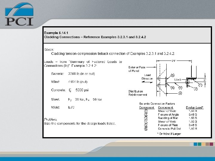
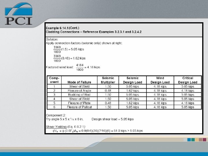
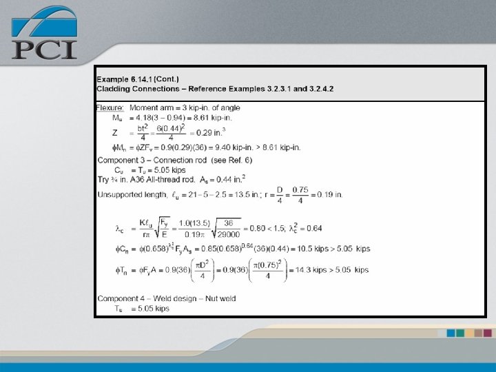
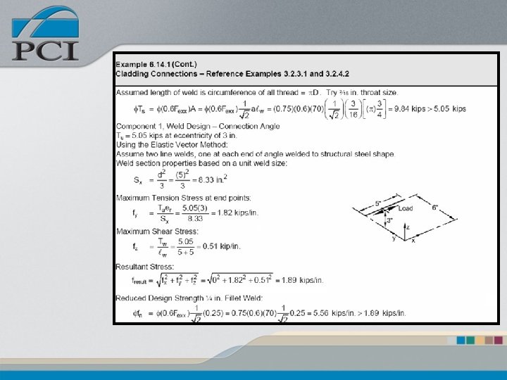
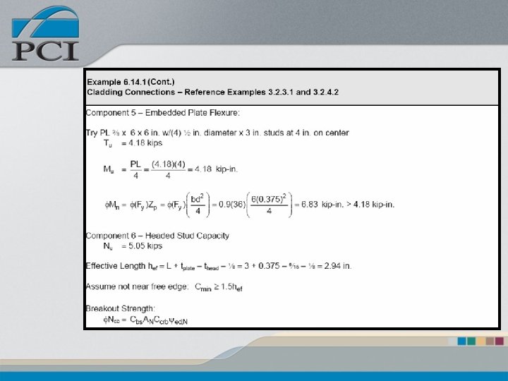
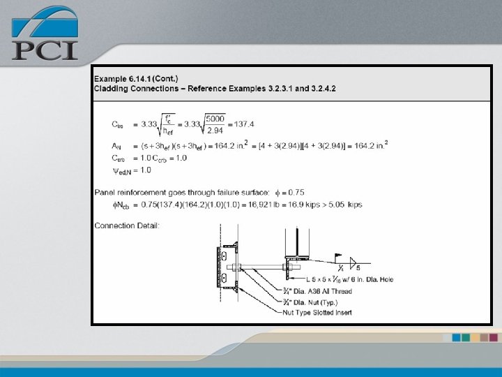
Completed Connection Examples • Examples Based – Applied Loads – Component Capacity • Design of all components – Embeds – Erection Material – Welds • Design for specific load paths
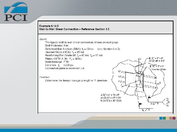
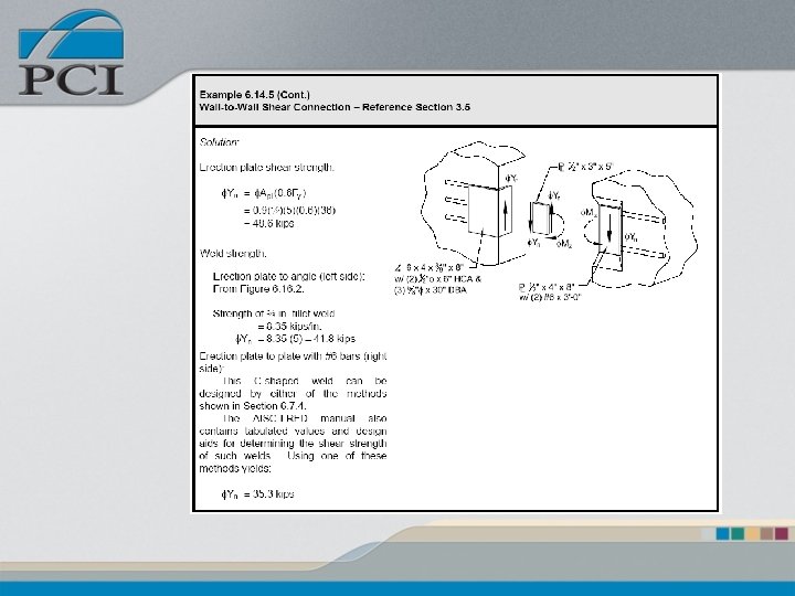
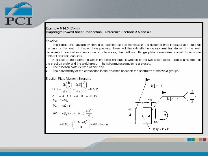
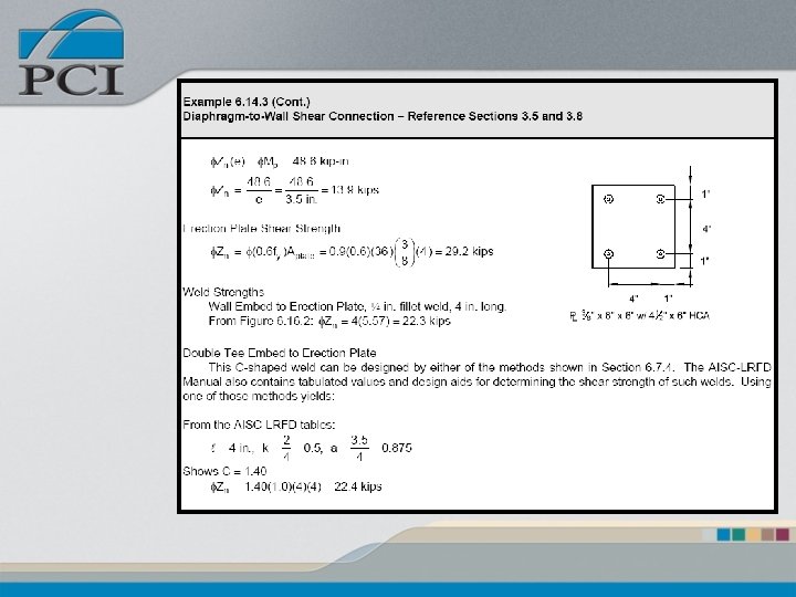
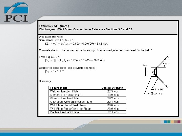
Completed Connection Examples • Cladding “Push / Pull” • Wall to Wall Shear • Wall Tension • Diaphragm to Wall Shear
Questions?