Outdoor Perimeter Intrusion Detection and Assessment Sensors Fox


 Sensors Categories • Analog or Digital Signal Processing •")


 or Monostatic (singleended) X-band (10. 525 GHz)")


 and amplitude changes caused")

 sensors • 8 -14 micron thermal detection.")


 and Analytics • Two components: – Sensor – a")
 and Analytics • Monostatic (single-ended) sensors. • Though considered")

 = 1 micron (mm)")


- Slides: 89
Outdoor Perimeter Intrusion Detection and Assessment Sensors Fox Valley Technical College Don Mc. Innes, Instructor
Topics to be Covered • Elements and Principles of outdoor Perimeter Intrusion Detection and Assessment Systems (PIDAS) • Types of commercial PIDAS sensors • Matching the sensor to the threat • Sensor defeat tactics – Non-classified – Primarily non-destructive • Summary & conclusions
Security System Elements 2. Assessment 1. Detection 2. Assessment 3. Delay 4. Response 3. Delay 1. Detection 4. Response
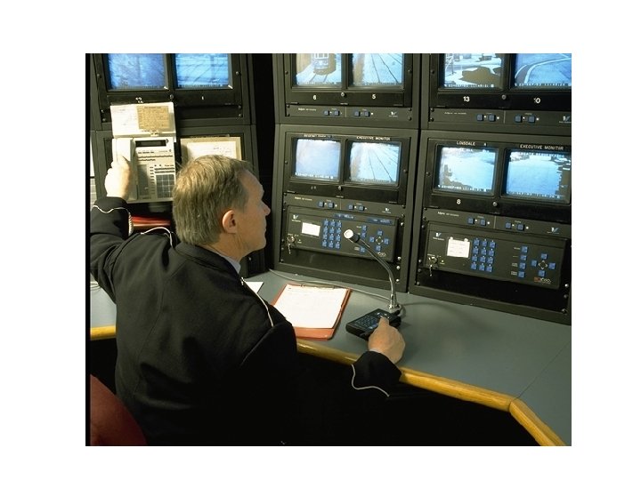
Respond Detect and Assess Delay Communicate Electronic PIDAS Sensors for Detection and Assessment Sensors provide: – – Means to detect intrusions or attempted intrusions within a defined protected area. Focus for assessment and response resources. • Sensors alone generally do not provide: – – Delay. Communications or response.
Typical Protection System Design Parameters • Protected area is often defined by a fence, wall, or other barrier. • Perimeter height coverage limited. • Detection of an aerial assault not easily addressed by sensors. • Probability of detection (PD) may be defined. • Minimum adversary size may be defined.
Typical System Design Parameters, continued • Adversary techniques such as climbing, crawling, jumping, running, or rolling may be defined. • Adversary speed may be defined. • “X” false and “X” nuisance alarms per zone per day/week/month may be defined.
Outdoor Sensor Types • No universal Source - Perimeter Security Sensor Technologies Handbook standard for categorizing sensors. (Infrared beams may be considered planar or volumetric) • Many sensors are differentiated by subtle proprietary features. • Some systems are hard to recognize in the field.
Electronic Perimeter Intrusion Detection (PIDS) Sensors Categories • Analog or Digital Signal Processing • Terrain Following or Line of Site • Volumetric or Planar Terrain Following Line of Site Volumetric Beam Volumetric Terrain Following Buried
Analog versus Digital Signal Processing Sensors • Analog sensors evaluate global changes. • More recent development - Digital Signal Processing (DSP) for PIDS. – Embedded or add-on to analog system. – Better target acquisition. – Better target discrimination. . – Better false/nuisance alarm rejection. – Pinpointing disturbances.
Analog versus Digital, continued Video movement detection – now referred to as video analytics - among the more mature digital technologies, and probably the most extensively researched. Some sensors can determine. . . – target speed and trajectory. – target size, mass. – Smaller target discrimination. – target identification - friend or foe.
Line of Site versus Terrain Following Sensors In general, the more rugged and obstructed the terrain, the more difficult it is to cover. A detection target must be in “full view” of a line of site sensor, for reliable detection. “Line of site” sensors may be blocked by terrain irregularities (such as street curbs, gullies, and depressions) of more than a few inches. Line of site detectors may be blocked by camera towers, fences, junction boxes, etc.
Line of Site versus Terrain Following Sensors • Individual line of site sensors may be deployed to follow rolling terrain or weave around obstructions, though often many more sensors than is practical may be required. • “Terrain following” sensors can more readily adapt to rolling terrain. • Sensor beds for terrain following or line of site sensors must be carefully prepared where bellycrawling targets need be detected.
Volumetric or Open Area versus Planar or Fence Line Sensors Planar sensors have two dimensional coverage - height or width within the distance covered. – Suitable for areas with limited “real estate”. – Sensor coverage relatively easy to discern, even with casual observation. Volumetric sensors have three dimensional coverage - height and width within the distance covered. – Detection pattern may be hard to discern, even with careful observation.
Volumetric or Open Area versus Planar or Fence Line Sensors, continued • Planar sensors usually require contact with a sensing plane - such as the ground or a fence.
Volumetric Sensors • Volumetric may be digital or analog. • May be terrain following or line of site. • Line of site systems – Microwave – Video detection – Passive infrared • Terrain following – Electric field – Buried/ported coax
Microwave Sensors Line of site. Bistatic (point-to-point) or Monostatic (singleended) X-band (10. 525 GHz) or K-band (21. 125 GHz) Now digital as well as analog sensors available. Microwave
Bistatic Microwave Considerations Clear Line of sight between transmitter and receiver required. Receiver look for decrease in signal caused by blockage or increase caused by reflection. Terrain must be flat. No vegetation over 3”- 4”. Maintain clearance from fence and other obstacles.
Bistatic Microwave Considerations, continued • Rigid mounting structure required. • Transmitter - receiver separation needed. • Overlap required between sensors. – Transmitter to transmitter and receiver to receiver on overlaps. – High security may dictate overlaps up to 25’. • Near unlimited height coverage through “stacking. ” – Single sensor mounting height from 18” to 36”. – Rotate heads 90 degrees for non-interfering “out of phase” signals.
Microwave Requires Overlap Tx Tx Rx OOOO Tx Rx Tx OOO Rx Rx Tx Rx
Monostatic Microwave Considerations Single sensor “transceivers” look at frequency (Doppler) and amplitude changes caused by moving objects. Wide detection pattern possible. Most sensitive to objects moving toward sensor. Obstructions cause irregularities in detection pattern.
Monostatic Microwave Considerations, continued Terrain must be flat for crawl detection. No vegetation or wet/reflective moving foreign material tolerated. Maintain clearance from fence and other obstacles. Rigid mounting structure required. Overlap required to accommodate limitations in sensor coverage pattern. Transceivers must be electronically synchronized if they are to be aimed at one another.
Outdoor Passive Infrared Sensors • Monostatic (singleended) sensors • 8 -14 micron thermal detection.
Passive Infrared Considerations • Pyroelectric detector looks for infrared energy emitted from moving objects, as a function of surface temperature and size. • Clear line of sight required for complete coverage. • Most sensitive to objects moving across sensor. • Terrain must be flat. • No vegetation over 3”- 4”.
Passive Infrared Considerations, continued. • Maintain clearance from fence and other obstacles. • Tall, rigid mounting structure required. • Overlap required between sensors. – Mounting height may dictate overlaps up to 25’. • Must be aimed downward to avoid detection of distant large moving objects (trains or airplanes).
Outdoor Video Movement Detection (VMD) and Analytics • Two components: – Sensor – a CCTV camera or thermal detector producing video-type image. – Detector and analytics – processor evaluating changes in the image.
Outdoor Video Movement Detection (VMD) and Analytics • Monostatic (single-ended) sensors. • Though considered line of site, typically mounted higher to provide for coverage of uneven terrain. • Visible (550 to 700 nanometer) ; invisible (near infrared to 1 micron), and thermal (2. 5 to 14 micron) spectrum detection. • Beyond the visible spectrum, Monochrome images will be displayed.
Infrared is really a broad category Units: 1000 nanometers (nm) = 1 micron (mm)
Benefits of Thermal Imaging • See in complete darkness – Unlike daylight and lowlight cameras, thermal imagers sense heat. – Heat is emitted by all objects in our environment, even ice cubes. – So even in complete darkness, you get clear imagery.
Wide Angle SR 19 • 36° field of view – Detects targets at short to medium range
Typical Surveillance Tasks Object in field • Object moves within an area/field Crossing line • Object crosses one or more lines in a certain direction Loitering • An object moves within a defined field for a specified period Condition change • An object changes its state, for example, a person slips and falls Following route • Object moves along a defined path Tampering • Camera is manipulated Removed object • A previously idle object disappears, e. g. in the event of theft. Idle object • A previously moving object is at rest, e. g. a piece of luggage is set down. Entering/Leaving field • An object enters/leaves a defined field. *
Outdoor Video Movement Detection Considerations Sensor connected to a camera monitors video light level changes within a scene. Wide detection pattern possible. Most outdoor VMD sensors designed to detect objects moving across sensor path. Obstructions and rain/snow blocking camera view limits detection.
Outdoor Video Movement Considerations, continued Camera and sensor perspective is generally high, so terrain need not be totally flat for detection. Flexible detection patterns, and multiple patterns within a sensor. Discrimination for direction of target movement. Rigid camera mounting structure required. Usually not used as a primary sensor due to high nuisance alarm rate caused by clouds, vehicle headlights, other flashes of light.
Volumetric Electric Field Barrier “Modern” systems have volumetric detection – Field generator and wires – Sense wires – Earth ground Terrain following Fence or free standing Digital signal processing
Electric Field Barrier - Considerations Follows terrain Good height coverage possible Installation costs major factor - poles spaced at frequent intervals, with many wires. Stable ground plane needed for best performance.
Electric Field Barrier Considerations, continued • Insulators must remain free of debris. • Sense wires must remain taut. • Ground must remain free of depressions (wash-out, etc. )
Surface and Buried Volumetric Technologies RF Field – Leaky/ported coax – Transmit and receive wires (FM) Fiber Optic – May be over-represented as a volumetric sensor. – More similar to strain sensitive. Buried
Buried - Considerations Covert in most cases Follows terrain Burial and servicing costs major factor Site traffic needs to be considered Soil consistency important
Buried - Considerations, continued • Limited height coverage. • One of few sensors capable of detecting tunneling.
Planar Sensor Technologies Line of site – Infrared multibeam Terrain following - stand alone – Taut wire Terrain following - fence, wall, or ground mounted – – Acoustic Strain Sensitive Fiber Optic Electrical shock system.
General Considerations - Planar Systems • Use small area in one dimension • Require contact with the sense plane. • Coverage pattern may be relatively easy to discern.
Covert Non-Volumetric Sensor Buried Fiber Optic • Fiber Optic – Sometimes over-represented as a volumetric sensor. – Detects vibration and pressure changes occurring on the ground. – Cable laid in a lengthwise serpentine pattern on a carefully prepared sensor bed. – Uniform sensitivity only if the sensor is bed is uniform. – No point impact location.
Covert Non-Volumetric Sensor Buried Fiber Optic, continued • Installation parameters: – Gravel – 3 -6” of ¾” gravel below, with 3” more on top. – Lawn – 12” serpentine pattern. Moist lawn required. Intruder must step directly over cable. – Sand – under 4” of sand. – Snow load will dampen vibration. – Limited cable pull strength.
Infrared Multibeam Line of site. Beams must be closely spaced together for adequate coverage. Suitable for areas with narrow or “high disturbance” isolation zones. Sensitive to nominal blockage.
Infrared Multibeam, continued • More sophisticated DSP systems available to evaluate disturbances between beams, to profile target. • New systems - Hymatom
Infrared Multibeam, continued The system is equipped with an active, video-analytic column and a test pattern column with IR LEDs. The video-analytic column contains a video camera equipped with a special filter, which visualizes through a set of swiveling mirrors. Every single intrusion hides differently one or several images of the contrast test pattern column according to the mirror height. The detection zone is uninterrupted (more than 500 consecutive layers) up to 3 meters in height. Thanks to the high density of layers, the system measures precisely the breach by triangulation, including qualifying the breach (dimensions and location), choosing a threshold alarm (according to the dimensions and size of the breach) and discriminating false alarms. The alarm thresholds are simply configured via a Web page (by minimal breach size or breach duration). The system constitutes a virtual IR wall which locates precisely each point. It is perfectly suitable for perimeter surveillance of sensitive sites, thanks to its high outdoor-detection range, its resistance to all environmental conditions and its ability to detect intrusion on a nonsmooth terrain.
Taut Wire Terrain following Free standing or fence mounted. Detects minute wire deflection. Sense wires must be closely spaced together for adequate coverage. An easy detection pattern to identify.
Strain/Vibration Sensing Terrain following Point sensors - sensing devices connected by wires are spaced at regular intervals. Best detection is near the sensing device. Continuous sensors use a cable as a sensor, and therefore have more uniform sensitivity.
Strain/Vibration Sensing, continued • Many phenomena used for detection. – Transducers – Geophones – Fiber optic cable • Sophisticated DSP available – “Point of impact” and sensitivity leveling now available
Ground Current/Shock Sensor Senses current to ground Intruder shocked: nonlethal or lethal. Free standing or fence mounted. Sense wires must be closely spaced together for adequate coverage.
Other Sensing Technologies Magnetic point detection. Ultrasonic/Acoustic o Sound waves and patterns Ground radar o Small (human) target acquisition capability still limited
Newer Smarter Sensors Advanced digital signal processing – Evaluate and act on more sensor information – Ability to locate point of intrusion and source of nuisance alarms Computer software or microprocessor driven Distributed power and communications – Lower installed cost Remote diagnostics and control
Dual Tech Sensors Dual technology in one package, “AND” gated together, may provide greater false alarm and nuisance alarm performance. May be suitable for commercially monitored systems, where nuisance alarms cause problems. Often two marginally good sensors combined in one unit, for cost savings. If one sensor can be beaten, the sensor is beaten. Not recommended for higher levels of security.
Multiple, Complementary Systems for Defense-In-Depth Dual technology may provide a higher probability of detection, if systems operate independently (OR gate mode). Overcomes limitation of a single sensor.
Multiple, Complementary Systems, continued • Reduce nuisance alarms by reducing individual sensor sensitivity.
Assessment for More Effective Response Assessment complements detection systems. Facilitate timely effective response Assessment: – Eyes-on – Audio – Video 2. Assessment 3. Delay 1. Detection 4. Response
Audio Assessment • Some sensors have “audio listen-in”, that provides additional detection feedback. • Usually requires trained operator. Video Assessment b CCTV provides visual assessment. b Some systems have pan, tilt, zoom to an alarm sector. b Some systems store and replay video of an event. b. Very low light assessment feasible. b. Remote assessment available over phone, LAN/WAN
Site Evaluation - Matching Sensors to the Threat • • • Target Threat Response Environment Real Estate Fence mounted
What is the Target? • • What is being protected? Where is the target? What barriers are there? What are the time lines?
What is the Threat? What must the system protect against? – “Design basis threat” - who are the “bad guys”? – Sophisticated, determined, knowledgeable adversaries with tools, weapons, explosives? – Outsiders with insider assistance? – How much time will they have? Owner expectations – No Exploitable pathways. – Balance false alarm and performance with threat.
Response? What should occur when the system goes into alarm? – Local response available? – Will the operator know the alarm is “real”? – Will the operator know what to expect? – Back-up on alert? How long will it take to respond to the alarm? – Multiple zones to pinpoint intrusion – Audio/visual (CCTV) to assess source of alarm
Environment? • What is the physical geography of site? – Level/uneven, rough/smooth, vegetation – Buildings or objects on perimeter – Distance from back-up response • What factors will impact system operation? – Weather extremes, fog, high winds, snow – Railroads, highways, personnel traffic
Real Estate? • How much land is available? – Barrier systems require least space – Beam systems need width – Buried systems require most space. • How much land area must be protected? – Determine critical areas to protect based upon time lines.
Site Evaluation Planning • Prepare a comprehensive site plan – Accurate map, drawing with dimensions – Note terrain issues (slopes, water) – Note assessment and response vulnerabilities. – AC power availability. – Areas to be protected.
Sensor Defeat Tactics Non-classified and non-destructive defeat tactics for outdoor perimeter intrusion detection and assessment systems.
Respond Detect and Assess Delay Communicate PIDAS for Detection and Assessment • Systems must address 3 adversary strategies 1. Deceit/diversion - Create false alarms to divert attention from actual intrusion, or use false pretenses to incapacitate or bypass sensor. 2. Stealth - Attempts to slowly and/or otherwise surreptitiously defeat systems. 3. Force - Fast attack to avoid intervention. Presumes detection and response is imminent.
PIDAS for Detection and Assessment, con’t. • PIDAS focuses upon stealth and early detection of forceful entry. • Deceit or diversion is addressed in sensor selection and system design. • Deterrent value may be nominal.
PIDAS must address adversary stealth/evasion tactics: 1. Alarm stacking 2. Camouflage 3. Other exploitable pathways - over, under, through or around. 4. Speed 5. Brute force
Non-Specific PIDAS Defeat Tactics Deceit/Diversion • Operators are “trained” through experience to expect false alarms rather than real alarms. • Sensors can often be triggered remotely. – Animals released. – Projectiles and other foreign objects. – Electro-mechanical disturbance.
Non-Specific PIDAS Defeat Tactics Deceit/Diversion, continued. • Frequent false alarms may lead to inferior response or compensatory measures. • Multiple false alarms may “stack”, such that the operator loses the ability to assess and respond to real alarms promptly.
Non-Specific PIDAS Defeat Tactics Deceit/Diversion, continued. • Intruder may simulate an environmental disturbance such as lightning, to defeat alarm assessment. – “Invisible” light flash (infrared) may be used. – After flash, camouflage may be used to conceal intruders. – Obstructions in the protected area may further conceal intruders.
Non-Specific PIDAS Defeat Tactics Deceit/Diversion, continued. • Intruder may observe walk test lights or listen for alarm relay activation to map sensor coverage. – Some “dual tech” sensors have a pre-alarm walk test light. When the light is observed, intruder may stop to wait for sensor to reset. • Intruders may observe testing and monitor results on non-encrypted radios.
Non-Specific PIDAS Defeat Tactics Vaulting and Bridging • Sensors may be deployed where fences, trees, communication and power lines, camera towers, sensor structures, and other structures provide vaulting and bridging platforms. – Easily possible for a fit, well-trained person to vault over 15 feet into a perimeter from an 8 foot fence.
Non-Specific PIDAS Defeat Tactics Vaulting and Bridging, continued • Sensors may be deployed where erosion is common, providing and opportunity to tunnel. • Sensors may not cover culverts, pipe lines, or tunnels into the protected areas.
Bistatic Microwave Vulnerabilities Block beam to form a penetration pathway. Exploit washout and depressions. Exploit snowfall. Vault-over single stacked sensors. “Weave” between inadequate offset. Crawl under sensors with little overlap. Very slow movement usually required.
Monostatic Microwave Vulnerabilities Block beam to form a penetration pathway. Exploit washout and depressions. Exploit snowfall. Vault-over single stacked sensors. “Weave” between sensors offset. Use RADAR absorbing material. Crawl under sensors with little overlap. Move slowly across sensor path.
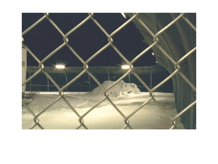
Outdoor Passive Infrared Vulnerabilities Prone to false alarms, so may not be calibrated for high sensitivity. Block sensor to form a penetration path. Exploit washout and depressions. Exploit snow build-up. Exploit sensors when ambient temperatures approach skin temperature. Move slowly in a diagonal line toward and across sensor path.
Video Movement Detection and Analytics Vulnerabilities • Rain, darkness, or bright sun aimed at camera limits detection. • Ice/frost build-up on camera housings limits detection. • Systems provide frequent nuisance alarms, so are a good candidate for alarm stacking. • Slow moving, camouflaged targets may evade detection. • Very large target/quick movement.
Volumetric Electric Field Barrier Vulnerabilities Systems are difficult to deploy around buildings or other obstructions, so look for gaps between sense wires and barriers. Look for deficiencies in ground reference plane (suspended systems). Look for loose wires or dirt/debris accumulation on insulators, indicating possibility of frequent of nuisance alarms. Look for erosion under wires.
Surface and Buried Volumetric Vulnerabilities Wooden stilts or fiberglass plasterer’s stilts may be feasible. Fence-to-fence bridging may be feasible. Two-man vault may be feasible. Look for wash-outs and differences in ground conditions within a detection zone. Easier to defeat if sensor position is detected – look for signs of parallel trencheor saw cuts in concrete or asphalt.
Buried Planar Vulnerabilities • Sensors have no height coverage, so vaultover or structure to structure bridging may be feasible. • Mattress or other dense material may be used to dampen sound. • Two-man vault may be feasible. • Look for accumulated snow, wash-outs and differences in ground conditions within a detection zone.
Infrared Multibeam Vulnerabilities Beams can be observed with infrared goggles or monochrome CCTV camera. Beam separation usually widest in the middle height range of the sensor. Climb over infrared mounting structure. Stimulate false alarms with intense (invisible) IR sources. Use fiber optic bundle to transmit beam between transmitter and receiver.
Taut Wire Vulnerabilities Detection pattern easy to discern. Clamp, jumper, and cut sense wires. Look for compressed springs and loose wires, especially during high temperature periods. Climb between wires. Use mounting hardware as a climbing aid. Look for coverage deficiencies around buildings and other obstructions. Ladders.
Ground Current/Shock Sensor Vulnerabilities Coverage pattern among the easiest to discern. Electrical insulation effective. Look for compressed springs and loose wires during high temperature periods. Use mounting hardware as a climbing aid. Look for coverage deficiencies around buildings and other obstructions.
Strain/Vibration Sensing Vulnerabilities • Pad shoes and hands or dampen sound on fence by leaning in with mattress. • Look for point sensors, and penetrate on fence panels without sensors. • Melt plastic cable ties and slowly lower sensor off of the fence using string. • Observe sensor height, and lean ladder or lift fence if high/low coverage not provided.
Strain/Vibration Sensing Vulnerabilities, continued • Strain sensitive sensors often have pulse counters, making a slow fence cut/wait scenario feasible. – Vertical fence slits can be created with relatively few cuts, and are very hard to find.
Summary and Conclusions • No single sensor is impenetrable. • As sensors become more sophisticated in order to suppress false alarms, the potential for defeat increases. • Detection without assessment is unacceptable.