Metallurgy of High Strength Steel N Yurioka Visiting


 Steel (at high temp. ), Austenitic")


 a Fe 3 C")

")


 • General structure • Welded structure • Building construction SS")

")


 Boilers u")

, Arc Energy(EN standard) EI(J/mm) =")
 at 540 o. C t 8/5(s): Cooling")


 diagram")
")
")
")


 Hardenability Carbon equivalent CEIIW CEWES")

/15 + (Cr +")
 Solidification cracking Liquation cracking u Cold")


 Toe crack (HAZ) Under-bead crack (HAZ) Transverse crack (Weld")


 = 1440 Pc - 392")


 MA of very hard phase Initiation site of brittle")


 It enables easy arc")
 High hydrogen Only for mild")


 = Weight of deposited metal /")


 Reheated Low heat input welding for lowtemperature")


 Boilers u")


- Slides: 97
Metallurgy of High Strength Steel N. Yurioka Visiting Professor at Osaka University
Crystalline lattice structure BCC FCC HCP
Crystalline lattice structure a. Face centered cubic (FCC) Steel (at high temp. ), Austenitic stainless steel, Al, Cu, . . . b. Body centered cubic (BCC) Steel (at low temp. ), Ferritic stainless steel, Ti (at high temp. ) c. Hexagonally closed packed (HCP) Ti (at low temp. )
Fe-C Phase diagram Steel is an alloy of Iron and carbon Iron C < 0. 02% Steel 0. 02 C 0. 21% Cast iron : 0. 21% < C
Phase transformation in cooling - I
Pearlite (Composite of ferrite and cementite) a Fe 3 C
Phase transformation in cooling - II
Line expansion (Dilatation)
Dilatometry-I
Dilatometry-II Transformation In heating Ac 1: a to g start Ac 3: a to g finish In cooling Ar 3: g to a start Ar 1: g to a finish In rapid cooling (quenching) Ms: M start Mf: M finish
Diffusion of carbon plays an important role in phase transformation
Microstructure of steels -I Martensite Lower bainite
Martensite and lower bainite
Microstructure of steels -II Rolling direction Upper bainite Ferrite and pearlite
Formation of upper bainite in cooling -I Nucleation of ferrite Growth of ferrite
Formation of upper bainite in cooling -II
Heat treatment of steels
Normalizing treatment of ferrite-pearlite steel Grain refining
Hot rolling processes
Microstructure of hot rolled steel As rolled TMCP-II Normalized Quenched & tempered
Features of steels • As rolled steel Ferrite –pearlite • Normalized steel Grain-refined ferrite-pearlite Higher strength and toughness Low strength, Low YR • TMCP-II (controlled rolling and accelerated cooling) steel Grain-refined ferrite + low temperature transformation product High strength and toughness, low CE (better weldability) • Quenched and tempered steel Tempered martensite, highest strength, high YR, high CE (preheating) Cautions for TMCP and QT steels: Heat input limitation ( 4. 5 k. J/mm), No hot forming
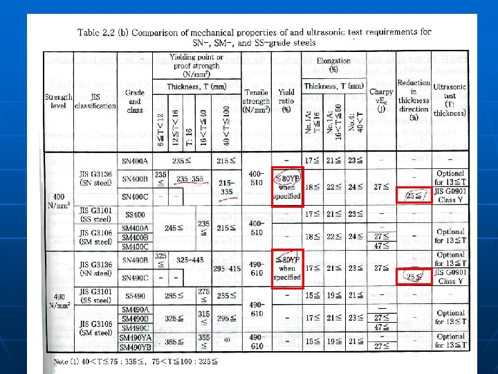
Mild steels (JIS standard) • General structure • Welded structure • Building construction SS series (SS 400, SS 490, etc…) SM series SN series ( Tensile strength )
n Steels for • Welded structures SM series
YR (Yield Ratio)
n Steels for Building construction SN series High ratio decreases the compliance of structures such as building.
Lamellar tear Reduction of P & S in steel Increase of RAz Reduction of area, RAZ in the thickness direction
n Steels for • Building construction SN series
High strength steel • TS >= 490 MPa SM 490, SM 520, SM 570…. . • Reduction of weight of structures Bridge, Storage tank, Pressure vessel Submarine, …… • Increase of production efficiency (Reduction of welding passes) Pipeline, ……. Welding of QT steel, TMCP steel Max allowable heat input 4. 5 k. J/mm to avoid HAZ softening, Low HAZ toughness
Steels for specific purposes u Lamellar tear resistant steel Ex. Z 25 grade (RA >= 25%) u Steel for very high heat input welding u Fire resistant steel u Hot-dip galvanizing crack resistant steel u Atmospheric corrosion resistant steel (Weathering steel, SMA series)
Low temperature service steels u JIS SLA grade Al-killed steel (N or QT or TMCP) u JIS SL grade 3. 5%Ni (NT, TMCP) 5%Ni (NNT, TMCP) 9%Ni (QQT, QLT, DQT) u Austenitic stainless steel SUS 304, SUS 316 u Inver (34%Ni-Fe) Welding of low temperature steels (QT, TMCP) Low heat input welding ( 35 k. J/mm desired)
-160 o. C
High temperature service steels u JIS G 3103 SB series (C, Mo) Boilers u u JIS G 3119 SBV series (Mn-Mo, Mn-Mo-Ni) JIS G 3120 SQV series (Mn-Mo, Mn-Mo-Ni) Nuclear pressure vessels u JIS G 4109 SCMV series (Cr-Mo) 1%Cr-9%Cr u JIS 4110 SCMQ series (Cr-Mo-V-(W)) 9 -12%Cr
Weldability of steels
Welding heat input Energy Input (AWS D 1. 1), Arc Energy(EN standard) EI(J/mm) = 60 · (E·I/v) E(V), I(A), v(mm/min) 60· 25· 170/150 1700 (J/mm), 1. 7(k. J/mm) Heat Input HI(J/mm) = EI : Arc thermal efficiency 1. 0 for SAW 0. 8 for SMAW, GMAW 0. 6 for autogenus TIG
Welding cooling rate, cooling time CR(o. C/s) at 540 o. C t 8/5(s): Cooling time between 800 o. C and 500 o. C 1. 7 k. J/mm on 20 mm thick 7 s in t 8/5
Cooling rate, Cooling time u Heat input u Plate thickness u u Joint shape (Butt-joint, fillet-joint) Preheat temperature Prediction of cooling time, t 8/5 JWES IT-Center (http: //www-it. jwes. or. jp/index_e. jsp)
45 mm
Microstructure of HAZ Normalizing heat treatment
CCT (Continuous Cooling Transformation) diagram
Cooling curve (log-scale)
CCT (Low-hardenability)
CCT (high hardenability)
HAZ maximum hardness
Hardness change against t 8/5
Change in HAZ maximum hardness Martensite hardness = f(C) Hardenability Carbon equivalent CEIIW CEWES
Prediction of HAZ hardness • Welding conditions t 8/5 HAZ hardness Heat input Plate thickness Preheat temperature • Chemical composition of steel C Carbon Equivalent JWES IT-Center (http: //www-it. jwes. or. jp/index_e. jsp)
Carbon equivalent CEIIW = C + Mn/6 + (Cu + Ni)/15 + (Cr + Mo + V)/5 CEWES = C + Si/24 + Mn/6 + Ni/40 + Cr/5 + Mo/4 + V/14
Weld cracking u Hot cracking (>1200 o. C) Solidification cracking Liquation cracking u Cold cracking (<100 o. C) (Hydrogen assisted cracking)
Hot cracking Solidification crack Liquation crack Stainless steel, Al
Weld metal cracking
Segregation of impurities during solidification Phase diagram Residual liquid phase
H/W Direction of solidification growth Welding velocity
Cold cracks Root crack (HAZ) Toe crack (HAZ) Under-bead crack (HAZ) Transverse crack (Weld metal)
Generation and diffusion of hydrogen Generation of hydrogen Mineral water in flux, Moisture in flux Moisture in atmosphere, Rust, oil, grease in groove Hydrogen diffusion in weld Arc H (hydrogen)
Effect of preheat on HAZ hydrogen
Cause of hydrogen-assisted cold cracking Diffusible hydrogen Weld metal hydrogen Preheat temperature Cold cracking Hardness (HAZ, Weld metal) Steel chemical composition t 8/5 HI, thickness Tensile residual stress Yield strength of weld metal Notch concentration factor
Cold cracking • Hydrogen assisted cracking, Delayed cracking
Determination of necessary preheat temperature AWS D 1. 1 Annex I Hardness control method (CEIIW) C>0. 11% Hydrogen control method (Pcm) C<0. 11% BS 5135 [EN 1011 -2 A] (CEIIW) CET method [EN 10110 -2 B] (CET) CEN method (CEN) JWES IT -center (http: //www-it. jwes. or. jp/index_e. jsp) Pc method (Pcm)
Carbon equivalents
Pc method Necessary preheat temperature Tph(o. C) = 1440 Pc - 392
Cracking other than hot cracking and cold cracking Lamellar tear Reheat crack
Prevention of lamellar tear u Use steel with higher RA in the thickness direction RAz > 15%, RAz > 25% u Avoid excessive amount of deposited weld metal u Employ buttering pass sequence u Prevent cold crack which may initiate lamellar tear
Prevention of lamellar tear Buttering pass Reduction of Deposited metal
Reheat crack Weld metal Coarse grained HAZ Reheat cracks are initiated at the weld toe during stress relief annealing Intergranular crack Prevention of reheat crack u Reduce stress concentration at the weld toe by grinding, etc. u Use appropriate steel with reduced amount of precipitation element such as Cr, Mo, V, Nb u Low heat input welding
HAZ toughness
Normalizing Heat treatment & HT 490
v. Trs Toughness of coarse grained zone Lower bainite Upper bainite
HAZ toughness u Refined grain at the coarse grained zone of HAZ Smaller heat input (HI)welding Steel with dispersed fine particles (Ti. N, oxide) u Microstructure with high toughness Increase of lower bainite Decrease of upper bainite and MA(island-like martensite) Low HI u Matrix High HI with high toughness Low N, High Ni High C
Impeding of austenite grain growth Austenite grain boundary migration is stopped by the pinning effect of particles. Ti deoxidized steel
Island-like martensite (MA, Martensite-Austenite constituent) MA of very hard phase Initiation site of brittle crack Low carbon steel Decrease of MA
Welding consumables
Typical covered electrodes Low hydrogen HD<7 ml/100 g Non low hydrogen HD > 30 ml/100 g Hydrogen level Type of covered flux Main ingredient JIS designation Welding position Ilminite D__01 Ilmenite All Lime-Titania D__03 Lime + Titanium oxide (Rutile) All Cellulosic D__11 Organic substance All High titanium oxide (Rutile) D__13 Titanium oxide (Rutile) All Low hydrogen D__16 Lime All Iron powder Low hydrogen D__26 Lime + Iron powder Flat Horizontal (Rutile) (Basic type) (Impure rutile)
Gravity welding equipment D 4326
Flux type of covered electrode Basic type Ca. CO 3 lime Ca. O + CO 2 High basicity Low hydrogen Decrease of partial pressure of H Low oxygen in weld metal
Functions of the coating of covered electrode for SMAW. (a) It enables easy arc ignition. (b) It stabilizes the arc. (c) It generates neutral gas for shielding weld from the air. (d) It forms slag which covers and protects the weld metal from air. (e) It makes de-oxidation and refines weld metal. (f) It improves the properties of weld by adding effective alloying elements (g) It increases deposition rate by adding iron powder.
u Non-low hydrogen electrode (HD > 30 ml/100 g) High hydrogen Only for mild steel Low basicity Higher oxygen content Lower toughness Rutile (Ti-oxide) Good workability Less generation of spatter and blowholes u Low hydrogen electrode (HD < 7 ml/100 g) Low hydrogen For mild steel and high strength steel Basic type of flux Lower oxygen content Higher toughness Poorer workability More generation of spatter and blowholes
Moisture absorption of electrode Baking condition for low hydrogen electrodes: 300 -400 o. C x 30 -60 min Drying condition for non-low hydrogen electores: 70 -100 o. C x 1 hr
Specification of solid wire for MAG welding
Solid wire for building structure welding
Effect of Ti in solid wire
Deoxidization reaction in MAG welding In welding arc, CO 2 CO + O In molten weld metal and slag, In the case of sufficient Si & Mn Into slag Fe + O Fe. O Si + Fe. O Si. O 2 + Fe Mn + Fe. O Mn. O + Fe In the case of insufficient Si & Mn Fe + O Fe. O C + Fe. O CO + Fe Blow hole
Prevention of blowhole Cause of blowhole • Hydrogen Decrease of moisture, rust in welding materials • CO gas Entry of air into shielding gas Stable flow of shielding gas (appropriate gas flow rate) Wind velocity 2 m/s (7 km/hr) Avoidance of excessively long arc length
Yield of Si & Mn in MAG welding CO 2 wire x Ar-CO 2 shielding gas Excessive Si & Mn in weld metal Excessive strength Ar-CO 2 wire x CO 2 shielding gas Insufficient Si & Mn in weld metal In sufficient strength
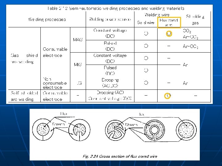
Flux cored wire YFW – C 50 2 X Flux type ( R: Rutile, M: Metalic, B: Basic, G: Other ) Charpy absorbed energy and temperature Tensile strength Shielding Gas (C: CO 2, A: Ar+CO 2)
Features of MAG welding processes Slag type of FCW : All position welding with high current Self shield arc welding : No supply of shielding gas
Efficiency of welding consumables u u Deposition efficiency(%) = Weight of deposited metal / weight of melted consumable Melting rate (g/min) = Melting speed of consumable per unit time (wire diameter, welding current, wire extension) Spatter loss (%) = Total weight of spatter / weight of melted consumable Deposition rate (g/min) = Weight of deposited metal per unit time (melting rate, penetration)
Flux for submerged arc welding n n n Fused flux Sintered flux Bonded flux
Comparison of SAW flux Property Fused type Bonded type Addition of alloying element Not possible Possible Resistance to moisture absorption Good Poor Diffusible hydrogen content Slightly high Low High speed welding Applicable Not applicable Very high heat input welding Not applicable Applicable
Macro-structure of weld metal As-solidified (as cast) Reheated Low heat input welding for lowtemperature steel k. J/mm
Microstructure of as-solidified weld metal Upper. Up bainite Ferrite + pearlite t 8/5 30 s Acicular ferrite
Intragranular nucleation of acicular ferrite in as-solidified weld metal during cooling transformation
Welding of high temperature service steel
High temperature service steels u JIS G 3103 SB series (C, Mo) Boilers u u JIS G 3119 SBV series (Mn-Mo, Mn-Mo-Ni) JIS G 3120 SQV series (Mn-Mo, Mn-Mo-Ni) Nuclear pressure vessels u JIS G 4109 SCMV series (Cr-Mo) 1%Cr-9%Cr u JIS 4110 SCMQ series (Cr-Mo-V-(W)) 9 -12%Cr
High temperature service steel Cr: Oxidation resistance at high temperatures by Cr oxide film Mo and Cr(less than 1%): Creep resistance Creep : Grain boundary slip Creep rupture is likely in fine grained zone Highest creep resistance Single crystal
Welding of high temperature service steel • High Cr and Mo High CE (Highly hardenable) 100% martensite in HAZ • Preheating is required to avoid cold cracking at HAZ Ex: 2. 25 Cr -1 Mo 9 Cr – 1 Mo 150 – 350 o. C 200 – 350 o. C • PWHT (stress relief annealing) is required to obtain tempered martensite in HAZ