Lecture 25 Capacitors and Inductors Introduction Capacitors Series


- Slides: 71

Lecture 25 Capacitors and Inductors • • • Introduction Capacitors Series and Parallel Capacitors Inductors Series and Parallel Inductors

Introduction • • Resistor: a passive element which dissipates energy only Two important passive linear circuit elements: 1) Capacitor 2) Inductor • Capacitor and inductor can store energy only and they can neither generate nor dissipate energy.

Capacitors • A capacitor consists of two conducting plates separated by an insulator (or dielectric).

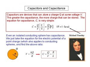
When a voltage source v is connected to the capacitor, the source deposits a positive charge q on one plate and a negative charge −q on the other. The capacitor is said to store the electric charge. Capacitance The amount of charge that a capacitor can store per unit of voltage across its plates is its capacitance, designated C. That is, capacitance is a measure of a capacitor's ability to store charge. The more charge per unit of voltage that a capacitor can store, the greater its capacitance, as expressed by the following formula:

By rearranging the terms C=Q/V, we can obtain two other formulas. Q= CV V= Q /C The Unit of Capacitance The farad (F) is the basic unit of capacitance. Recall that the coulomb (C) is the unit of electrical charge. One farad is the amount of capacitance when one coulomb (C) of charge is stored with one volt across the plates.

Although the capacitance C of a capacitor is the ratio of the charge per plate to the applied voltage v, it does not depend on q or v. Three factors affecting the value of capacitance: 1. Area: the larger the area, the greater the capacitance. 2. Spacing between the plates: the smaller the spacing, the greater the capacitance. 3. Material permittivity: the higher the permittivity, the greater the capacitance.

Circuit symbols for capacitor According to the passive sign convention, current is considered to flow into the positive terminal of the capacitor when the capacitor is being charged, and out of the positive terminal when the capacitor is discharging.

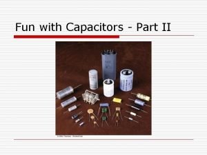
Fixed-value capacitors Polyester capacitors are light in weight, stable, and their change with temperature is predictable. Instead of polyester, other dielectric materials such as mica and polystyrene may be used. Film capacitors are rolled and housed in metal or plastic films. Electrolytic capacitors produce very high capacitance. (a) Polyester capacitor, (b) Ceramic capacitor, (c) Electrolytic capacitor

Variable Capacitors The capacitance of a trimmer capacitor is varied by turning the screw. The trimmer capacitor is often placed in parallel with another capacitor so that the equivalent capacitance can be varied slightly. Variable capacitors are used in radio receivers allowing one to tune to various stations. In addition, capacitors are used to block dc, pass ac, shift phase, store energy, start motors, and suppress noise. Variable capacitors: (a) trimmer capacitor, (b) filmtrim capacitor.

Charge in Capacitors The relation between the charge in plates and the voltage across a capacitor is given below.

Voltage Rating Since q=Cv, the plate charge increases as the voltage increases. The electric field intensity between two plates increases. If the voltage across the capacitor is so large that the field intensity is large enough to break down the insulation of the dielectric, the capacitor is out of work. Hence, every practical capacitor has a maximum limit on its operating voltage.

I-V Relation of Capacitor + v - i C

+ v i C - capacitor voltage depends on the past history of the capacitor current. Hence, the capacitor has memory—a property that is often exploited.

Power and Energy Storing in Capacitor + v V=q/c - i C

important properties of a capacitor + v i C - • when v is a constant voltage, then i=0; a constant voltage across a capacitor creates no current through the capacitor, the capacitor in this case is the same as an open circuit. • A capacitor is an open circuit to dc. However, if a battery (dc voltage) is connected across a capacitor, the capacitor charges.

The derivative of a time-varying quantity is the instantaneous rate of change of that quantity. • The voltage on the capacitor must be continuous • The voltage on a capacitor cannot change abruptly. • If v is abruptly changed, then the current will have an infinite value that is practically impossible. Hence, a capacitor is impossible to have an abrupt change in its voltage except an infinite current is applied.

• For example, the voltage across a capacitor may take the form shown in Fig (a), whereas it is not physically possible for the capacitor voltage to take the form shown in Fig. (b) because of the abrupt change. Conversely, the current through a capacitor can change instantaneously. Abrupt change

An alternative way of looking at this is using Eq. which indicates that energy is proportional to voltage squared. Since injecting or extracting energy can only be done over some finite time, voltage cannot change instantaneously across a capacitor.

• The ideal capacitor does not dissipate energy. It takes power from the circuit when storing energy in its field and returns previously stored energy when delivering power to the circuit. • A real, non ideal capacitor has a parallel-model leakage resistance, as shown in Fig. The leakage resistance may be as high as 100 M and can be neglected for most practical applications.

Example 1 (a) Calculate the charge stored on a 3 -p. F capacitor with 20 V across it. (b) Find the energy stored in the capacitor.

Example 1 Solution: (a) Since (b) The energy stored is

Example 2 • The voltage across a 5 - F capacitor is Calculate the current through it. Solution: • By definition, the current is

Example 3 • Determine the voltage across a 2 - F capacitor if the current through it is Assume that the initial capacitor voltage is zero. Solution: • Since

Example 4 • Obtain the energy stored in each capacitor in the shown Fig. under dc condition.

Example 4 Solution: • Under dc condition, we replace each capacitor with an open circuit. By current division,

Parallel Capacitors

Parallel Capacitors • The equivalent capacitance of N parallelconnected capacitors is the sum of the individual capacitance.

Series Capacitors

Series Capacitors • The equivalent capacitance of seriesconnected capacitors is the reciprocal of the sum of the reciprocals of the individual capacitances.

Example 5 • Find the equivalent capacitance seen between terminals a and b of the circuit in the Fig.

Example 5 Solution:

Example 6 • For the circuit in Fig, find the voltage across each capacitor.

Example 6 Solution: • Two parallel capacitors: • Total charge • This is the charge on the 20 -m. F and 30 -m. F capacitors, because they are in series with the 30 -v source. ( A crude way to see this is to imagine that charge acts like current, since i = dq/dt)

Example 6 • Therefore, • Having determined v 1 and v 2, we now use KVL to determine v 3 by • Alternatively, since the 40 -m. F and 20 -m. F capacitors are in parallel, they have the same voltage v 3 and their combined capacitance is 40+20=60 m. F.

Inductor • An inductor is a passive element designed to store energy in its magnetic field. • Inductors find numerous applications in electronic and power systems. They are used in power supplies, transformers, radios, TVs, radars and electric motors. • Any conductor of electric current has inductive properties and may be regarded as an inductor. But in order to enhance the inductive effect, a practical inductor is usually formed into a cylindrical coil with many turns of conducting wire.

Inductor • An inductor is made of a coil of conducting wire • Inductors are formed with wire tightly wrapped around a solid central core

Inductance (or electric inductance) is a measure of the amount of magnetic flux produced for a given electric current. The inductance has the following relationship: L= Φ/i where – L is the inductance in henrys, – i is the current in amperes, – Φ is the magnetic flux in webers

If current is allowed to pass through an inductor, it is found that the voltage across the inductor is directly proportional to the time rate of change of the current. Using the passive sign convention, where L is the constant of proportionality called the inductance of the inductor. The unit of inductance is the henry (H), named in honor of the American inventor Joseph Henry (1797– 1878).

Various types of inductors: (a) solenoidal wound inductor, (b) toroidal inductor (c) chip inductor. The inductance of an inductor depends on its physical dimension and construction

Like capacitors, commercially available inductors come in different values and types. Typical practical inductors have inductance values ranging from a few microhenrys (μH), as in communication systems, to tens of henrys (H) as in power systems. Inductors may be fixed or variable. The core may be made of iron, steel, plastic, or air. The terms coil and choke are also used for inductors. The circuit symbols for inductors are shown below following the passive sign convention. (a) air-core (b) iron-core (c) variable iron-core

Flux in Inductors • The relation between the flux in inductor and the current through the inductor is given below. φ Linear Nonlinear i

I-V Relation of Inductors • An inductor consists of a coil of conducting wire. i + v Figure shows this relationship graphically for an inductor whose inductance is independent of current. Such an inductor is known as a linear inductor. For a nonlinear inductor, the plot of Eq. will not be a straight line because its inductance varies with current. L -

+ v L - where i(t 0) is the total current for −∞ < t 0 and i(−∞) = 0. The idea of making i(−∞) = 0 is practical and reasonable, because there must be a time in the past when there was no current in the inductor.

The inductor is designed to store energy in its magnetic field + v L - • The energy stored in an inductor

important properties of inductor • When the current through an inductor is a constant, then the voltage across the inductor is zero, same as a short circuit. • An inductor acts like a short circuit to dc. • The current through an inductor cannot change instantaneously.

According to Eq. a discontinuous change in the current through an inductor requires an infinite voltage, which is not physically possible. Thus, an inductor opposes an abrupt change in the current through it. For example, the current through an inductor may take the form shown in Fig. (a), whereas the inductor current cannot take the form shown in Fig. (b) in real-life situations due to the discontinuities. However, the voltage across an inductor can change abruptly.

• Like the ideal capacitor, the ideal inductor does not dissipate energy. The energy stored in it can be retrieved at a later time. The inductor takes power from the circuit when storing energy and delivers power to the circuit when returning previously stored energy. • The inductor can be used to generate a high voltage, for example, used as an igniting element.

Model of a Practical Inductor A practical, non ideal inductor has a significant resistive Component. This is due to the fact that the inductor is made of a conducting material such as copper, which has some resistance. This resistance is called the winding resistance Rw, and it appears in series with the inductance of the inductor. The presence of Rw makes it both an energy storage device and an energy dissipation device. Since Rw is usually very small, it is ignored in most cases. The Non ideal inductor also has a winding capacitance Cw due to the capacitive coupling between the conducting coils. Cw is very small and can be ignored in most cases, except at high frequencies.

Example 1 The current through a 0. 1 -H inductor is i(t) = 10 te-5 t A. Find the voltage across the inductor and the energy stored in it. Solution:

Example 2 • Find the current through a 5 -H inductor if the voltage across it is Also find the energy stored within 0 < t < 5 s. Assume i(0)=0. Solution:

Example 2

Example 3 • Consider the circuit in Fig (a). Under dc conditions, find: (a) i, v. C, and i. L. (b) the energy stored in the capacitor and inductor.

Example 3 Solution:

Inductors in Series

Series Inductor • Applying KVL to the loop, • Substituting vk = Lk di/dt results in

Inductors in Parallel

Parallel Inductors • Using KCL, • But

Example 5 Find the equivalent inductance of the circuit shown in Fig.

Example 5 • Solution:

Practice Problem

Example 6 • For the circuit in Fig, If find :

Example 6 Solution:

Example 6

Table

Applications of Capacitors and Inductors Circuit elements such as resistors and capacitors are commercially available in either discrete form or integratedcircuit (IC) form. Unlike capacitors and resistors, inductors with appreciable inductance are difficult to produce on IC substrates. Therefore, inductors (coils) usually come in discrete form and tend to be more bulky and expensive. For this reason, inductors are not as versatile as capacitors and resistors, and they are more limited in applications. However, there are several applications in which inductors have no practical substitute. They are routinely used in relays, delays, sensing devices, pick-up heads, telephone circuits, radio and TV receivers, power supplies, electric motors, microphones, and loudspeakers, to mention a few.

Capacitors and inductors possess the following three special properties that make them very useful in electric circuits: 1. The capacity to store energy makes them useful as temporary voltage or current sources. Thus, they can be used for generating a large amount of current or voltage for a short period of time. 2. Capacitors oppose any abrupt change in voltage, while inductors oppose any abrupt change in current. This property makes inductors useful for spark or arc suppression and for converting pulsating dc voltage into relatively smooth dc voltage.

3. Capacitors and inductors are frequency sensitive. This property makes them useful for frequency discrimination. The first two properties are put to use in dc circuits, while third one is taken advantage of in ac circuits.

Summary 1. The current through a capacitor is directly proportional to the time rate of change of the voltage across it. The current through a capacitor is zero unless the voltage is changing. Thus, a capacitor acts like an open circuit to a dc source. 2. The voltage across a capacitor is directly proportional to the time integral of the current through it. The voltage across a capacitor cannot change instantly.

Summary ors 3. 4. way as conductances. time rate of change of the current through it. The voltage across the inductor is zero unless the current is changing. Thus an inductor acts like a short circuit to a dc source.

Summary 5. The current through an inductor is directly proportional to the time integral of the voltage across it. The current through an inductor cannot change instantly. 6. Inductors in series and in parallel are combined in the same way resistors in series and in parallel are combined

Summary 7. At any given time t , the energy stored in a capacitor is while the energy stored in an inductor is.
 Inductor in dc circuit
 I = c dv/dt example
 Self inductance symbol
 Voltage across capacitors in series
 Uses of inductors
 Potential energy of capacitor
 What is ohm's law solved for current? i = v/r v= i/r r= i/v
 01:640:244 lecture notes - lecture 15: plat, idah, farad
 Geology lecture series
 Dcac lecture series
 Series aiding and series opposing
 Fun with capacitors
 Paralleling capacitors
 How to calculate the capacitance of a capacitor
 C=q/v
C=q/v Energy stored in capacitors
 Kvl with capacitors
 Energy in the capacitor
 High precision capacitors
 The basics of capacitors
 Maclaurin series vs taylor series
 Heisenberg 1925 paper
 Taylor vs maclaurin
 Taylor series lesson
 P series ibm
 General
 Arithmetic sequence formula
 Introduction to biochemistry lecture notes
 Introduction to psychology lecture
 Introduction to algorithms lecture notes
 Summation
 Electricity and magnetism lecture notes
 Power system dynamics and stability lecture notes
 Microbial physiology notes
 Limits fits and tolerances
 Cloud computing lecture
 Hole basis fits
 Financial institutions and markets lecture notes ppt
 Indirect finance
 Extempore and lecture
 Utilities and energy lecture
 Catherine belsey books
 Application of mechatronics ppt
 Obstetrics and gynecology lecture notes ppt
 Lecture on love courtship and marriage
 Power system dynamics and stability lecture notes
 Project planning and management lecture notes ppt
 Anterior and medial compartment of thigh lecture
 Pros and cons of series and parallel circuits
 Arithmetic and geometric sequences and series
 Essay structure
 Project procurement management lecture notes
 Lecture about sport
 Healthy lifestyle wrap up lecture
 Nihilism vs existentialism
 Meaning of this
 Randy pausch the last lecture summary
 Tensorflow lecture
 Theology proper lecture notes
 Strategic management lecture
 Social psychology lecture
 In text citation for a lecture
 Advantages of government accounting
 Project management lecture notes doc
 Reinforcement lap lengths eurocodes
 Classical mechanics
 Physics 101 lecture
 Physical science lecture notes
 Natural language processing nlp - theory lecture
 Objectif de la lecture en primaire
 Instruction de lecture et d'écriture
 Aronautique
