
High precision low ripple 3 k V capacitor


- Slides: 18
High precision, low ripple 3 k. V capacitor charger S. Blume, D. Gerber and J. Biela Laboratory for High Power Electronic Systems ETH Zürich
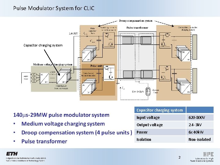
Pulse Modulator System for CLIC • Capacitor charging system Input voltage 620 -800 V Output voltage 2. 4 -3 k. V Power 6 x 40 k. W Isolation Non-isolated 2
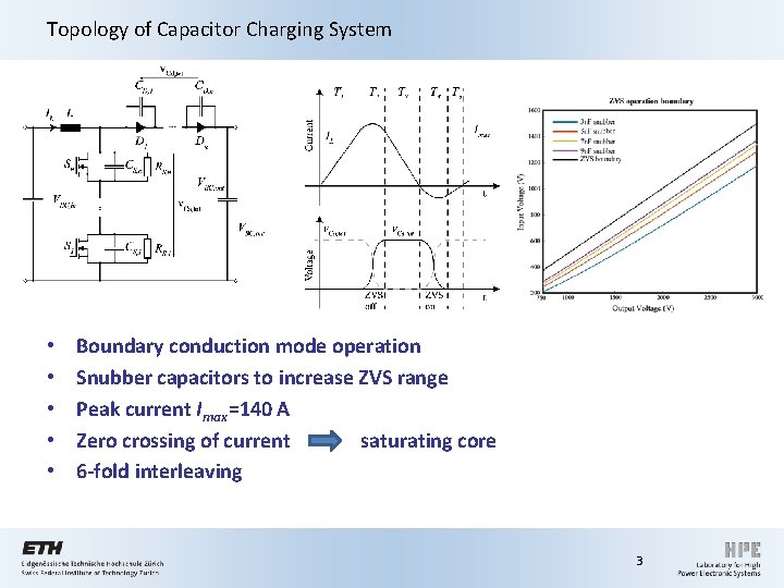
Topology of Capacitor Charging System • • • Boundary conduction mode operation Snubber capacitors to increase ZVS range Peak current Imax=140 A Zero crossing of current saturating core 6 -fold interleaving 3
I. Control of capacitor charging system 4
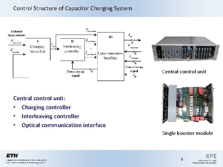
Control Structure of Capacitor Charging System Central control unit: • Charging controller • Interleaving controller • Optical communication interface Single booster module 5
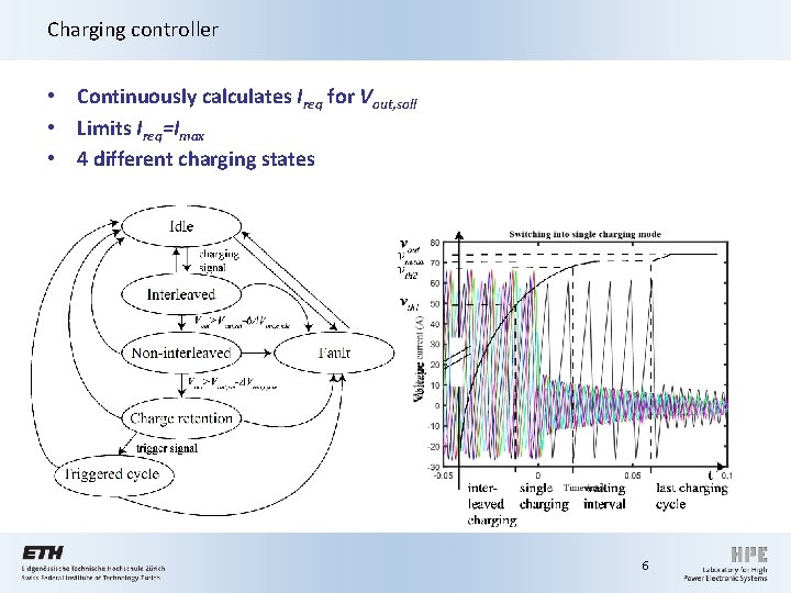
Charging controller • Continuously calculates Ireq for Vout, soll • Limits Ireq=Imax • 4 different charging states 6
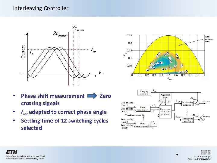
Interleaving Controller • Phase shift measurement Zero crossing signals • Iset adapted to correct phase angle • Settling time of 12 switching cycles selected 7
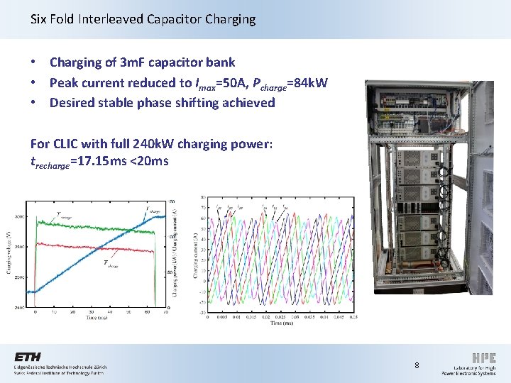
Six Fold Interleaved Capacitor Charging • Charging of 3 m. F capacitor bank • Peak current reduced to Imax=50 A, Pcharge=84 k. W • Desired stable phase shifting achieved For CLIC with full 240 k. W charging power: trecharge=17. 15 ms <20 ms 8
II. Repeatability analysis of capacitor charging system 9
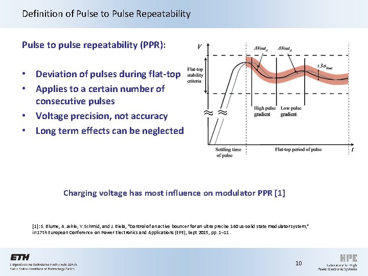
Definition of Pulse to Pulse Repeatability Pulse to pulse repeatability (PPR): • Deviation of pulses during flat-top • Applies to a certain number of consecutive pulses • Voltage precision, not accuracy • Long term effects can be neglected Charging voltage has most influence on modulator PPR [1]: S. Blume, A. Jehle, Y. Schmid, and J. Biela, “Control of an active bouncer for an ultra precise 140 us-solid state modulator system, ” in 17 th European Conference on Power Electronics and Applications (EPE), Sept 2015, pp. 1– 11. 10
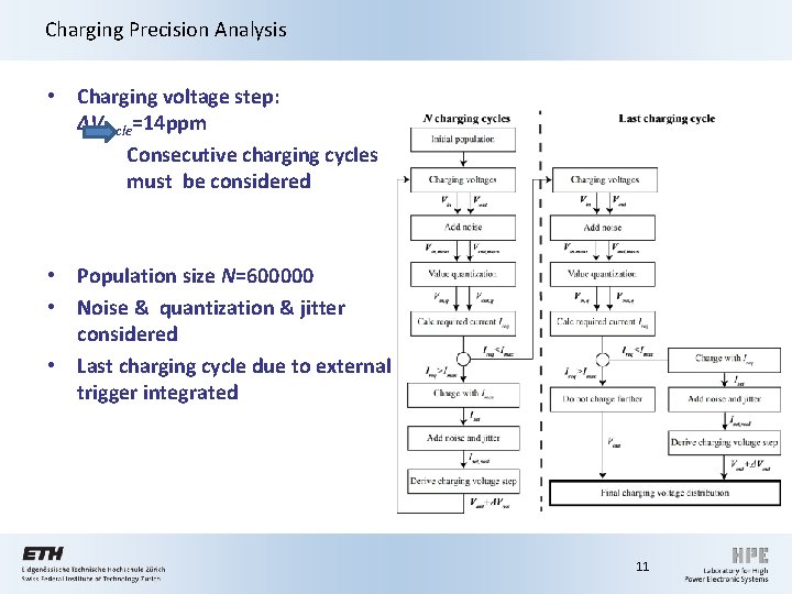
Charging Precision Analysis • Charging voltage step: ΔVcycle=14 ppm Consecutive charging cycles must be considered • Population size N=600000 • Noise & quantization & jitter considered • Last charging cycle due to external trigger integrated 11
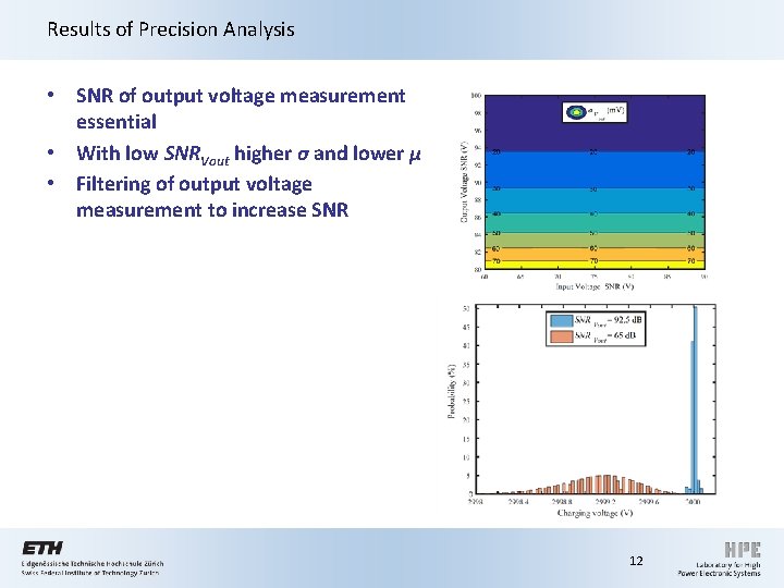
Results of Precision Analysis • SNR of output voltage measurement essential • With low SNRVout higher σ and lower µ • Filtering of output voltage measurement to increase SNR 12
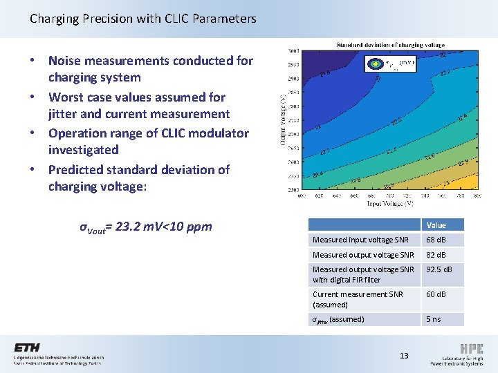
Charging Precision with CLIC Parameters • Noise measurements conducted for charging system • Worst case values assumed for jitter and current measurement • Operation range of CLIC modulator investigated • Predicted standard deviation of charging voltage: σVout= 23. 2 m. V<10 ppm Value Measured input voltage SNR 68 d. B Measured output voltage SNR 82 d. B Measured output voltage SNR with digital FIR filter 92. 5 d. B Current measurement SNR (assumed) 60 d. B σjitter (assumed) 5 ns 13
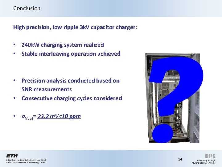
Conclusion High precision, low ripple 3 k. V capacitor charger: • 240 k. W charging system realized • Stable interleaving operation achieved • Precision analysis conducted based on SNR measurements • Consecutive charging cycles considered • σVout= 23. 2 m. V<10 ppm 14
15
16
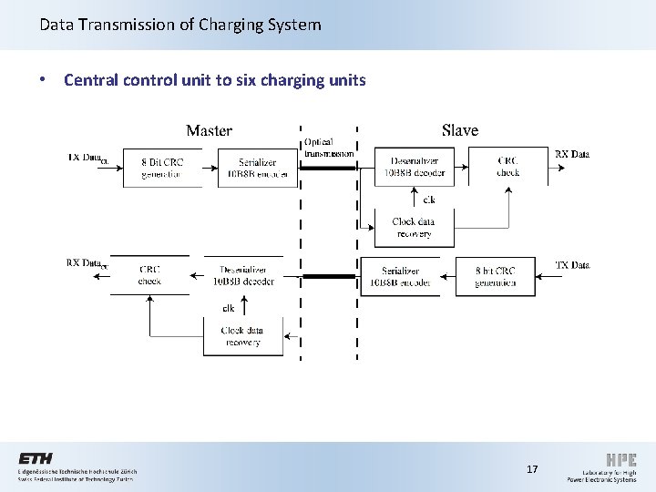
Data Transmission of Charging System • Central control unit to six charging units 17
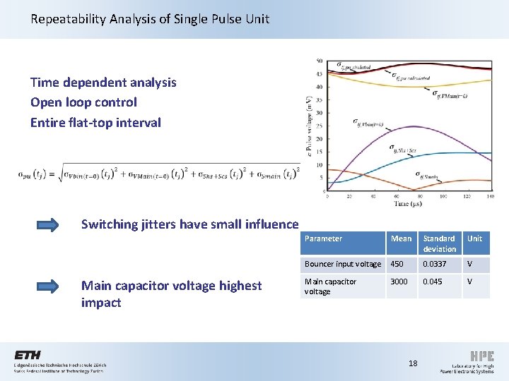
Repeatability Analysis of Single Pulse Unit Time dependent analysis Open loop control Entire flat-top interval Switching jitters have small influence Main capacitor voltage highest impact Parameter Mean Standard deviation Unit Bouncer input voltage 450 0. 0337 V Main capacitor voltage 3000 0. 045 V 18