1 CHAPTER ONE Fits and Tolerances CHAPTER ONE


 (it represents the")


 Number or Grade IT 01, IT")


- Slides: 49
1 CHAPTER ONE : Fits and Tolerances
CHAPTER ONE : Fits and Tolerances
CHAPTER ONE : Fits and Tolerances Why tolerances and fits are required? Due to the inevitable inaccuracy of manufacturing methods, a part cannot be made precisely to a given dimension, the difference between maximum and minimum limits of size of a part is the tolerance. Tolerance is the total amount that a specific dimension is permitted to vary. There is no such thing as an "exact size". Tolerance is key to interchangeable parts. When two parts are to be assembled, the relation resulting from the difference between their sizes before assembly is called a fit.
CHAPTER ONE : Fits and Tolerances Examples of Interchangeable Manufacture Bottle caps Rims Tires
CHAPTER ONE : Fits and Tolerances Advantages For Interchangeable Manufacture Replacement: One such part can freely replace another, without any custom fitting (such as filling). Easy to Assembly: This interchangeability allows easy assembly of new devices Repairing: Easier repair of existing devices. Minimizing time and cost: Minimizing both the time and skill required of the person doing the assembly or repair. Rapid Manufacturing: Machine tool enables the components to be manufactured more rapidly
CHAPTER ONE : Fits and Tolerances How to decide tolerance? Functional requirements of mating parts Cost of production Available manufacturing process Choose as coarse tolerance as possible without compromising functional requirements. Proper balance between cost and quality of parts.
CHAPTER ONE : Fits and Tolerances 1. 1 Dimensional Tolerances Some of the dimensional tolerances terms are defined as follows: 1. Dimension (A dimension is "a numerical value expressed in appropriate units of measure and indicated on a drawing and in other documents along with lines, symbols, and notes to define the size or geometric characteristic, or both, of a part or part feature") 2. Size (It is a number expressed in a particular unit in the measurement of length) 3. Basic size (the theoretical size used as a starting point for the application of tolerances) 4. Actual size (of a part) (the measured size of the finished part after machining) 5. Design size (The ideal size for each component (shaft and hole) based upon a selected fit)
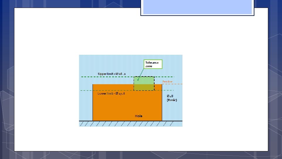
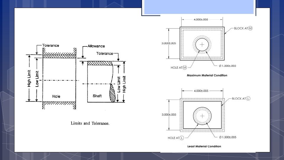
CHAPTER ONE : Fits and Tolerances 6. Limits of size (the maximum and minimum sizes shown by the tolerance dimension) 7. Maximum limit of size (Is the maximum size permitted for the part) 8. Minimum limit of size (it is the minimum size permitted for the part limit of size) 9. Maximum material limit (condition) (is the condition of a part when it contains the most amount of material. The MMC of an external feature (such as a shaft) is the upper limit. The MMC of an internal feature(such as a hole) is the lower limit) 10. Minimum material limit (condition) (is the condition of a part when it contains the least amount of material possible. The LMC of an external feature is the lower limit of the part. The LMC of an internal feature is the upper limit of the part. ) 11. Tolerance (Tolerance is the difference between maximum limit of size and minimum limit of size)
CHAPTER ONE : Fits and Tolerances 12. Zero line (Basic size) (it represents the basic size) 13. Upper deviation (It is the algebraic difference between minimum limit of size and its corresponding basic size) 14. Lower deviation (It is the algebraic difference between minimum limit of size and its corresponding basic size) 15. Tolerance zone (a region representing the difference between the upper and the lower limits) 16. Unilateral tolerance (In this method of presenting the limits, variation is allowed only on one side of the zero line) 17. Bilateral tolerance (Here the limits variation is allowed on either sides of the zero line) 18. Shaft (it refers to any external feature of a part, including any non cylindrical features as well) 19. Hole (the term used for any internal feature of a part including any non cylindrical as well)
Examples of holes and shafts
Video link to understand tolerances: https: //www. youtube. com/watch? v=Ki. XHABf. RHf. Q
Basic size Tolerance
Unilateral tolerance Bilateral tolerance Zero line
Calculate the maximum and minimum possible dimension for A +0. 1 -0. 1
CHAPTER ONE : Fits and Tolerances 20. Basic shaft (the shaft chosen as a basis for the shaft basis system of fit) 21. Basic hole (the hole chosen as a basis for the hole basis system of fit) 22. Fit (Fit is the relationship that exists between two mating parts, a hole and shaft with respect to their dimensional difference ) 23. Basic size of a fit (common value of the basic size of the two parts of a fit)
CHAPTER ONE : 24. Clearance fit Hole 25. Interference fit Fits and Tolerances Shaft Tolerance Zone of Hole Tolerance Zone of Shaft Hole 26. Transition fit
CHAPTER ONE : 27. Minimum clearance 28. Maximum clearance 29. Minimum interference Fits and Tolerances
CHAPTER ONE : Fits and Tolerances 30. Maximum interference 31. Shaft-basis system of fits 32. Hole-basis system of fits Figure 1. 3: Basic hole and shaft system
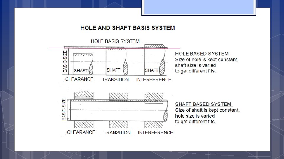
31 - Basic Shaft System of fits In this system the size of the shaft remains the same and the hole size is varied to get the required fit. Maximum shaft size is taken as the basic size, an allowance is assigned, and tolerances are applied on both sides of and away from this allowance.
32 - Basic Hole System of fits In this system the size of the hole remains the same and shaft size is varied to get the required fit. Minimum hole is taken as the basic size, an allowance is assigned, and tolerances are applied on both sides of and away from this allowance.
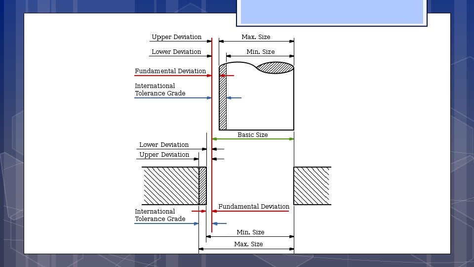
Some definitions Basic Size: is the size from which limits or deviations are assigned. Basic sizes, usually diameters, should be selected from a table of preferred sizes. Deviation: is the difference between the basic size and the hole or shaft size. Upper Deviation: is the difference between the basic size and the permitted maximum size of the part. Lower Deviation: is the difference between the basic size and the minimum permitted size of the part.
Or Zero deviation line
Some Definitions Fundamental Deviation: is the deviation closest to the basic size. This is identical to the upper deviation for shafts and the lower deviation for holes in a clearance fit.
Some Definitions The hole-basis system of preferred fits is a system in which the basic diameter is the minimum size of the hole. For the generally preferred hole-basis system, the fundamental deviation is specified by the upper-case letter. The shaft-basis system of preferred fits is a system in which the basic diameter is the maximum size of the shaft. The fundamental deviation is given by the lowercase letter.
Some Definitions An interference fit results in an interference between two mating parts under all tolerance conditions. A clearance fit results in a clearance between the two mating parts under all tolerance conditions. A transition fit results in either a clearance or an interference condition between two assembled parts.
CHAPTER ONE : Fits and Tolerances 1. 2 Symbols for Tolerances and Deviation and Symbols for Fits: 1. Tolerance values (The tolerance value is a function of the basic size and is indicated by a number called the grade. ) 2. Tolerance zone position The position of the tolerance zone with respect to the zero line, is indicated by a letter symbol, a capital letter for holes and a small letter The tolerance size thus defined by its basic value followed by a symbol composed of a letter and a number. It is established by a combination of the fundamental deviation indicated by a letter and the IT grade number. In the dimension 50 H 8, the H 8 specifies the tolerance zone. Example for shaft: 45 g 7 International Tolerance Grade (IT)
CHAPTER ONE : Fits and Tolerances 1. 2 Symbols for Tolerances and Deviation and Symbols for Fits: 3. A fit (A fit is indicated by the basic size common to both components, followed by symbol corresponding to each component, the hole being quoted first) Example: 45 H 8 g 7 Possibly 45 H 8 – g 7 Or 45 H 8/g 7 https: //books. google. com. sa/books? id=2 ck 0 Aw. AAQBAJ&pg=SA 6 -PA 13&lpg=SA 6 -PA 13&dq=fundamental+deviation+selection+fits+IT&source=bl&ots=ZOM 0 z. Nqb. P&sig=of. RGWezbx. Kz. Je 9 u. W 9 zwx. VZRZPdk&hl=en&sa=X&redir_esc=y#v=onepage&q=fundamental%20 deviation%20 selection%20 fits%20 IT&f=false
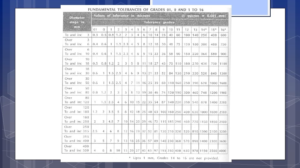
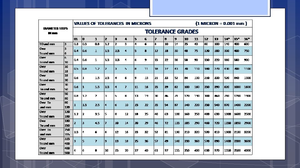
CHAPTER ONE : Fits and Tolerances 1. 3: Grades of tolerances: Eighteen grades of tolerances are provided IT 01, ITO and IT 1 to IT 16 The Table 1. 1 gives the possible degrees of precision or grade of tolerance, achieved with different machine tools.
CHAPTER ONE : Fits and Tolerances Table 1. 1: degree of precision or grade of tolerance Tolerance grade I T 01 I T 0 I T 1 I T 2 I T 3 I T 4 Intended for Applicable to components or machines Slip blocks, Reference gauges Gauges High quality gauges I T 5 I T 6 I T 7 I T 8 I T 9 I T 10 I T 11 Ball bearing Grinding, Honing Broaching Center lathe turning Worn automatic lathe Milling Drilling, Rough turning Fits I T 12 I T 13 I T 14 I T 15 I T 16 Not for fits Light press work Press work Die casting Stamping Sand casting
International Tolerance Grade Selection Representation of Tolerance 2) Number or Grade IT 01, IT 0, IT 1, …. IT 16 Tolerance Grade defines range of dimensions (dimensional variation) There are manufacturing constraints on tolerance grade chosen
Example
CHAPTER ONE : Fits and Tolerances Holes Shafts Figure 1. 5: Position of the various tolerance zones for a given diameter in the ISO system
Position of the various tolerance zones for a given diameter in the ISO system
Metric Preferred Hole Based System of fit
Metric Preferred shaft Based System of fit
https: //books. google. com. sa/books? id=2 ck 0 Aw. AAQBAJ&pg=SA 6 -PA 13&lpg=SA 6 PA 13&dq=fundamental+deviation+selection+fits+IT&source=bl&ots=ZOM 0 z. Nqb. P&sig=of. RGWezbx. Kz. Je 9 u. W 9 zwx. VZRZPdk&hl=en&sa=X&redir_esc=y#v=onepage&q=fundame ntal%20 deviation%20 selection%20 fits%20 IT&f=false Adapted from: Metrology & Measurement By Bewoor Table for fundamental deviations for shafts
https: //books. google. com. sa/books? id=2 ck 0 Aw. AAQBAJ&pg=SA 6 -PA 13&lpg=SA 6 PA 13&dq=fundamental+deviation+selection+fits+IT&source=bl&ots=ZOM 0 z. Nqb. P&sig=of. RGWezbx. Kz. Je 9 u. W 9 zwx. VZRZPdk&hl=en&sa=X&redir_esc=y#v=onepage&q=fundame ntal%20 deviation%20 selection%20 fits%20 IT&f=false Adapted from: Metrology & Measurement By Bewoor Table for fundamental deviations for shafts
https: //books. google. com. sa/books? id=2 ck 0 Aw. AAQBAJ&pg=SA 6 -PA 13&lpg=SA 6 PA 13&dq=fundamental+deviation+selection+fits+IT&source=bl&ots=ZOM 0 z. Nqb. P&sig=of. RGWezbx. Kz. Je 9 u. W 9 zwx. VZRZPdk&hl=en&sa=X&redir_esc=y#v=onepage&q=fundame ntal%20 deviation%20 selection%20 fits%20 IT&f=false Adapted from: Metrology & Measurement By Bewoor Table for fundamental deviations for holes
Please note that all values in this table are actually negative https: //books. google. com. sa/books? id=2 ck 0 Aw. AAQBAJ&pg=SA 6 -PA 13&lpg=SA 6 PA 13&dq=fundamental+deviation+selection+fits+IT&source=bl&ots=ZOM 0 z. Nqb. P&sig=of. RGWezbx. Kz. Je 9 u. W 9 zwx. VZRZPdk&hl=en&sa=X&redir_esc=y#v=onepage&q=fundame ntal%20 deviation%20 selection%20 fits%20 IT&f=false Adapted from: Metrology & Measurement By Bewoor Table for fundamental deviations for holes
CHAPTER ONE : Fits and Tolerances 1. 4 Fundamental tolerance unit: 1. 4. 2 Fundamental deviations: 1. 4. 2. 1 Shaft deviation: For each letter symbol defining the position of the tolerance zone, the magnitude and sign of one of the two deviations which is known as the fundamental deviations (upper deviation) “es” or lower deviation “ei” The other deviation is derived from the first one using the magnitude of the standard tolerance “IT”, by means of the following algebraic relationship: The fundamental deviation given by the formulae in above tables of deviations is, in principle, that corresponding to that limit closet to the zero line, in other words, the upper deviation “es” for shafts (a) to (h), and the lower deviation “ei” for shafts (j) to (Zc). ei = es - IT es = ei + IT
CHAPTER ONE : Fits and Tolerances 1. 4. 2. 2 Hole deviation: For each letter symbol, defining the position of the tolerance zone, the magnitude and sign of the fundamental deviation (lower deviation “EI” for holes (A) to (H) and upper deviation “ES” for holes (J) to (Zc), The other deviation is derived from the first one, using the magnitude of the tolerance “IT” by means of the following relationships. ES = EI + IT OR EI = ES - IT
Example Determine which type of fit is presented by H 7/p 6? For basic size of 30 mm determine the dimensions of the hole and the shaft for the given fit. (Fit: 30 H 7/p 6) Capital H means basic hole system and upper deviation = zero H 7 : Tol Grade 7 mean 21μ variation INTERFERENC E FIT Φ 30. 021 Φ 30. 000 p 6 : Tol Grade 6 means 13μ variation (p means lower deviation is 22 μ) Fit: 60 H 8/e 6 Φ 30. 035 Φ 30. 022
Example Creating a Clearance Fit using The Basic Hole System Given the following fit Φ 40 – H 11/c 11 From table for hole diameter = 40 and H 11 we find Upper deviation = +160 μm & Lower deviation = 0 From table for shaft diameter = 40 and c 11 we find Upper deviation = -120 μm & Lower deviation = -280 μm Calculations of dimension limits for hole and shaft - Maximum hole diameter = 40 + 0. 16 = 40. 16 mm - Minimum hole diameter = 40 + 0 = 40 mm - Maximum shaft diameter = 40 +(-120) = 39. 88 mm - Minimum shaft diameter = 40 + (-280) = 39. 72 mm Maximum clearance = Maximum hole diameter – Minimum shaft diameter = 40. 16 – 39. 72 = 0. 44 mm Minimum clearance = Minimum hole diameter – Maximum shaft diameter = 40 – 39. 88 = 0. 12 mm Allowances = minimum clearance Spring 2005= 0. 12 mm = 120 μm