Capacitors Inductors AH Physics Mr Stewart Capacitors Revision


- Slides: 22

Capacitors & Inductors AH Physics Mr Stewart

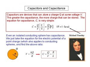
Capacitors – Revision from Higher �You have already met capacitors in Higher Physics. �Capacitors store charge �Capacitors store energy �The capacitance of a capacitor is a measure of how much charge it can store per volt across it. �Capacitance is measured in farads (1 F = 1 C V-1 )

Capacitors & D. C. �Capacitors take time to charge up. �The time taken for a capacitor to charge depends on �The size of the capacitor (C) �The resistance of the charging circuit (R) Bigger values of C & R result in longer charging and discharging times.

Time constant of a RC circuit (�) The product of resistance and capacitance is called the time constant of the circuit. . The time constant gives the time taken for a capacitor to charge to 63% Symbol τ is a Greek letter pronounced ‘tau’ In this circuit the time constant of the charging circuit (switch at position P) is: (The reason for this 63% arises from the mathematics of continuous growth and decay curves. More detail on this is given on the next slide but is not examinable!) A capacitor is said to be fully charged (or discharged) after 5 time constants. In this case the capacitor is fully charged after 42 seconds.

Time constant – the maths (interest only) �The growth and decay curves for voltage and current during the charging and discharging of a capacitor are exponential curves. �The voltage across a charging capacitor is given by the relationship: Where e is Euler’s number or the base of the natural logarithm Therefore after 1 time constant, 63% charged. After 5 time constants, 99% charged etc….

But why does RC equal a “time”? . . . � Remember: Q = It So when the values of a resistor and capacitor connected in series are multiplied together, the result is a quantity measured in the units of time.

Capacitors & A. C. �Capacitors block d. c. When a capacitor is full, no more current flows. �Capacitors will allow an alternating current to flow. This is because the capacitor lets charge move onto it as it charges, and off it as it discharges. So charge can move in an alternating fashion. At higher frequencies, charge is moving more of the time…………

Capacitive reactance �The effective rate of flow of charge (Irms) onto and off a capacitor depends on the size of the capacitor and the frequency of the a. c. supply. �The bigger the capacitor and higher the frequency, the easier it is for charge to continually move in the circuit. �A capacitor’s opposition to a. c. is called capacitive reactance (Xc) Reactance is similar to resistance in d. c. circuits but is frequency dependent. Reactance is measured in ohms. (Ω)

example a) Calculate the capacitive reactance of the capacitor in this circuit. b) Calculate the effective current (I rms) in the circuit when the Supply voltage is 10 Vrms and the frequency is 60 Hz. c) The frequency of the supply is increased to 120 Hz. State what happens to (i) the reactance of the capacitor (ii) the current in the circuit a) 27 ohms b) 0. 37 A c) (i) reactance decreases (ii) current increases

Inductors �An inductor is a component that has similar properties to a capacitor in that it can store energy and “reacts” to different frequencies in an a. c. circuit. �An inductor is basically a coil of wire with negligible resistance that uses the growth and decay of a magnetic field in its operation. You may have met this before if you studied electromagnetism and generation of electricity in National 4/5. Inductor symbol

Self-Inductance of a coil. If a magnet is moved in and out of a coil of wire, an alternating voltage is induced in the coil. �The size of this induced voltage depends on: �The size/ core of the coil �The strength of the magnet �The rate of change of the motion of the magnet This induced voltage does not require any external power supply and is therefore called the self-inductance of the coil.

Inductors in d. c. circuits �In a d. c. circuit, when the circuit is turned on, the sudden change in current produces a changing magnetic field around the coil that induces an Emf across the coil that opposes the change in current that causes it. �The induced Emf in a coil always opposes the change that causes it. (This is called Lenz’s Law) �This induced Emf is called a “Back-Emf”. (because it opposes the forward supply voltage) Watch

Back- Emf and rate of change of current • When the circuit is initially switched on, there is a large “rate of change” of current. (This is the gradient of the current time graph) • This causes a large changing magnetic field around the inductor which in turn induces a large back-emf across the coil. • This back-emf “slows” the rate of change of current which causes the back-emf to decrease. • The graph shows the gradient (d. I/dt) decreasing to zero as the back-emf decreases to zero as the current reaches its maximum value. Time (s) Note: At the instant of “switch-on” the back-emf is equal and opposite to the supply voltage

Inductors and d. c. The growth and decay graphs of current in an inductor in a d. c. circuit are similar to the charge and discharge graphs of voltage for a capacitor. When switched on, it takes time for the current to reach it’s maximum value. Similarly when switched off, it takes time for the current to fall to zero Switched on Switched off

Inductance of an inductor (L) �The inductance of an inductor is the ratio of the induced back-emf to the rate of change of current. Back-Emf (V) Inductance The unit of inductance is the henry (H) (1 henry = 1 V s A-1 or Ω s ) (This is named after Joseph Henry, America’s answer to Michael Faraday. ) Rate of change of current (A s-1) Minus sign is because the backemf is in the opposite direction to the forward current

Example a) (i) 0. 5 A t (ii) Large rate of change of current produces back-emf which opposes the growth of current. b)

Energy stored in an inductor Inductors store energy in the magnetic field around them. This energy can be released when the field collapses and a large emf is produced. Similar to a capacitor where the energy stored is given by: The energy stored in an inductor is given by: This energy can be released very quickly when a large coil is switched off. This can cause a large spark which can damage equipment, loss of data or cause an electric shock.

Inductive Reactance (XL) An inductor is another frequency dependent component. When placed in an a. c. circuit the inductor has an inductive reactance (XL) that depends on: �The inductance of the inductor, L, (in henrys) �The frequency, f, of the a. c. supply Reactance is similar to resistance in d. c. circuits but is frequency dependent. Reactance is measured in ohms. (Ω) Calculations can be carried out similar to Ohm’s Law:

example a) Calculate the inductive reactance of the inductor in this circuit. b) Calculate the effective current (I rms) in the circuit when the Supply voltage is 120 Vrms and the frequency is 60 Hz. c) The frequency of the supply is increased to 400 Hz. State what happens to (i) the reactance of the inductor (ii) the current in the circuit a) 113 ohms b) 1. 1 A c) (i) reactance increases (ii) current decreases

Applications of Capacitors & Inductors �Capacitors and Inductors are reactive components �They are used in audio systems as filters to ensure the correct audio frequencies are sent to the correct loudspeakers �Capacitors have low reactance at high frequencies �Inductors have low reactance at low frequencies. A capacitor is used in series with the “tweeter” speaker that produces high frequencies (treble). An inductor is used in series with the “woofer” that produces the low (bass) frequencies.

The defibrillator A defibrillator or AED is used to restart the normal beating of a persons heart. • Capacitor is charged up to a high voltage. • Switch is pressed and the capacitor is discharged through the patient. • The inductor is used to oppose the change of the current and ensures that the current is delivered to the patient at a high enough level for the required time. A inductor is used (instead of a resistor) to ensure all the energy is passed to the patient and not wasted as heat in a resistor.

Example 2017 paper. A capacitor and an inductor are used in a hi-fi loudspeaker circuit. a) Explain why a capacitor is used in series with the tweeter b) Explain why the inductor is used in series with the woofer. c) When the frequency of the input signal is 3. 0 k. Hz, the capacitor and inductor both have a reactance of 8 Ω. Calculate: (i) The capacitance of the capacitor (ii) The inductance of the inductor. a) To allow high frequencies to pass/ block low frequencies b) To allow frequencies to pass / block high frequencies c) (i) 6. 6 microfarads (ii) 0. 42 m. H
 Capacitors and inductors
 Equivalent inductance
 Self inductance
 Uses of inductors
 Passive revision
 Mr stewart physics
 Mr stewart physics
 Mr stewart physics
 Mr stewart physics
 What is ohm's law solved for current? i = v/r v= i/r r= i/v
 Energy stored in capacitors
 The basics of capacitors
 Capacitor series parallel
 Kvl capacitor
 Fun with capacitors
 Paralleling capacitors
 Energy in a capacitor
 Energy stored in parallel plate capacitor
 Energy density in electrostatic field
 Capacitors are devices that
 High precision capacitors
 Physics ia idea
 Modern physics vs classical physics
