Chapter 23 Electric Potential And Electric Potential Energy


 of an")
")


 • Polarization can")


- Slides: 137
Chapter 23 Electric Potential And Electric Potential Energy
Potential Energy • When we lift a stone of mass m a distance h above the ground the amount of work done in lifting the stone is equal to the change in potential energy of the stone.
Potential Energy cont. • Similarly the work done moving an electrical charge in an electric field can be expressed as the change in potential energy of the charge.
Potential • If we divide by the magnitude of the electric charge then we can define a quantity called the change in electric potential:
Potential cont. • The electric potential at a given point is defined as: • The unit of electric potential is joule / coulomb = volt.
Potential cont. • The electric potential difference between two points B and A is related to the work per unit charge in the following manner:
Example • The work done in moving a charge • qo = 2. 0 m. C from A to B is WAB = 5. 0 x 10 -5 J. • Find the difference in the electric potential energies of the charge and determine the potential difference between the points.
Solution • The change in potential energy is:
Solution cont. • The change in electric potential is:
Example: Conservation of Energy • A particle of mass 1. 8 x 10 -5 kg and a positive charge of 3. 0 x 10 -5 C. It is released from rest at a point A and accelerates horizontally until it reaches a point B. • The particle does not rotate as it moves. The only force acting on the particle is an electric force. The electric potential at point A is 25 volts greater than at point B. • What is the speed of the particle when it reaches point B?
Solution • By applying the conservation of energy and solving for the final velocity we get:
The Electric Potential Difference Created by Point Charges • A positive point charge creates an electric potential throughout all space around it. • The potential can be related to the work done on the charge moving it from point A to B. • The work done can not be given by the force multiplied to the distance moved because the force given by Coulomb's law varies as the particle moves further away from the test charge.
The Electric Potential Difference Created by Point Charges • We must therefore use the full definition of work to determine the potential. • If we divide by our charge qo then we get the potential difference.
The Electric Potential Difference Created by Point Charges • If we located our point B farther and farther away from the charge, then as r approaches infinity: • Then we can write the potential difference as:
Example • Using the zero reference potential at infinity, determine the amount by which a point charge of 4. 0 x 10 -8 C alters the electric potential at a spot 1. 2 m away when the charge is positive.
Solution • By definition of the potential difference from a point located at infinity we get the following: • Note: the symbol V is sometimes used to represent volts.
Example • Bart and Lisa Simpson are rubbing their feet on the carpet to create a static charge, which they intend to discharge on each other. • The pair accumulate -20 m. C each. • Meanwhile, Homer comes in to the room with a positive 20 m. C on him. • If Bart and Lisa are 2 m apart and homer forms an isosceles triangle with them at a distance of 4 m, what is the potential created halfway between Bart and Lisa?
The Simpsons -20 m. C
Solution
Electric Potential of a Point Charge • The electric potential in the plane around a single point charge is shown • The red line shows the 1/r nature of the potential
Electric Potential of a Dipole • The graph shows the potential (y-axis) of an electric dipole • The steep slope between the charges represents the strong electric field in this region
Active Figure 25. 10 (SLIDESHOW MODE ONLY)
The Potential Energy of a Group of Charges • Example: • Three point charges (+5. 0, +6. 0, -2. 0 )m. C are initially infinitely far apart. • They are brought together and placed at the corners of an equilateral triangle. • Each side of the triangle has a length of 0. 50 m. • Determine the electric potential energy of the triangular group.
Reasoning • We proceed in steps by adding charges to the triangle, one at a time, and then determine the electric potential energy at each step. • Every time we add a new charge the space around them changes; hence, the potential and potential energies change.
Solution • The order does not matter; we begin with the charge of +5. 0 m. C. • When the charge is placed at a corner of the triangle, it has no electric potential energy but it does produce a potential of:
Solution cont. • Now we can bring another charge in and place it at one of the other corners of the triangle. • The potential energy is given by the following:
Solution cont. • The electric potential produced at the remaining empty corner is the sum of the potentials due to the two charges that are already in place:
Solution cont. • When the third charge is placed at the remaining empty corner, its electric potential energy is:
Solution cont. • The total potential energy is the sum of the potential energies calculated earlier:
Electric Fields and the Electric Potentials • The relation between the electric field and the electric potential can be expressed the following way: • For one dimensional cases we can simplify the equation and write the expression in the following manner:
Example with the Gradient • Suppose that in a particular region of space the electric potential is given as:
Gradient cont. • Determine the electric field • Solution:
Solution cont.
Electric Fields and the Electric Potentials • If the potential change is uniform in one direction, and if we wish to look at the average electric field between two points along this direction then we can further simplify the equation:
Electric Fields and the Electric Potentials • The preceding equation shows that the electric field between two points along a distance s is equal to the change in potential along this path divided by the length of the path.
Example • The plates of a capacitor are separated by a distance of 0. 032 m, and the potential difference between them is -64 V. • Between two equipotential surfaces that are located between the plates there is a potential difference of -3. 0 V. • Find the spacing between the two equipotential surfaces.
Capacitor DV = -3 V 0. 032 m DV = -64 V
Solution • The electric field between the capacitor plates is • The spacing between the equipotential surfaces can now be determined:
Potential of an Infinite Line Charge • Consider the infinite line charge we encountered in the previous chapter. • We already know the electric field for this problem. + + + + +
Potential of an Infinite Line Charge • Suppose that we wish to determine the potential difference from the line at points ra and rb. • We integrate our electric field between those two points.
Potential of an Infinite Line Charge • It is not convenient to define the potential at infinity to be zero for this problem. • Therefore, we set Vb to be zero at the point rb.
Potential for a Ring Charge • Returning once more y to the previous chapter, lets consider the potential for a uniformly charged ring. a ds d. E q d d. Ex E x y
Potential for a Ring Charge • Since the potential is a scalar we do not need to consider the components this time. • We can divide our ring up into differential elements, dq and integrate directly.
The Potential of a Charged Conducting Sphere • Consider a solid conducting sphere of radius R and charge q. • Determine the potential at any point in space due to the sphere.
Solution • We can get the electric field of the sphere by using Gauss’s law. r 2 R r 1
Solution cont. • Since there are no charges inside the conducting sphere the electric field inside is zero.
Solution cont. • Outside the sphere the electric field looks like that of a point particle.
Solution cont. • We can get the potential by integrating the electric field.
Solution cont. • Solving for the potential outside the sphere we get:
Solution cont. • At the surface of the sphere the potential is:
Compare E to V for the Sphere • At the surface of the sphere we can write the following relationship for the electric field and the potential.
Ionization of Air • Air becomes a conductor at an electric field of around
Ionization of Air • Therefore, the maximum potential of a spherical conductor in air can be related by the following: • For a one centimeter sphere this is:
Chapter 24 Capacitance and Dielectrics
The Capacitance of a Capacitor • It can be shown experimentally that the potential between the plates of a capacitor is directly proportional to the charge that is on each plate. • The proportionality constant is called the capacitance and can be expressed in the following manner:
The Capacitance of a Capacitor • C represents the capacitance and has units of coulomb / volt = farad. • The unit of a farad is an enormous capacitance; therefore, microfarads or picofarads are normally used when expressing capacitance in most electrical circuits.
Dielectrics • If a dielectric substance is placed between the plates of a capacitor the capacitance can be greatly increased. • The expression for the dielectric constant is as follows:
Dielectrics • In the previous equation k represents the dielectric constant, E is the electric field with the dielectric in place and Eo is the field before the dielectric is placed between the plates. • Since Eo is always greater than or equal to E then the dielectric constant is always greater than or equal to 1.
Another Look at the Parallel Plate Capacitor • The capacitance of a capacitor is defined by the geometry of the plates and also by the dielectric constant. • If d is the distance between the plates then the magnitude of the electric field inside the dielectric is given by:
Another Look at the Parallel Plate Capacitor • If the charge on each plate is kept constant then the electric field of the capacitor is:
Another Look at the Parallel Plate Capacitor • The magnitude of the electric field between the plates of a parallel plate capacitor without a dielectric in place is: • It then follows that:
Another Look at the Parallel Plate Capacitor • A comparison with the expression for capacitance q = CV reveals that the capacitance for a parallel plate capacitor with a dielectric in between the plates is:
Example • The capacitance of an empty capacitor is 1. 2 microfarads. The capacitor is connected to a 12 V battery and charged up. • With the capacitor connected to the battery, a slab of dielectric material is inserted between the plates. As a result, 2. 6 x 10 -5 C of additional charge flows from one plate, through the battery, and on to the other plate. • What is the dielectric constant of the material?
Solution • The empty capacitor has a capacitance of 1. 2 microfarads and stores an amount of charge qo = Co. V. • With the dielectric material in place, the capacitor has a capacitance C= k. Co and stores an amount of charge q = (k. Co)V.
Solution cont. • The additional charge that the battery supplies is:
Solution cont. • Solving for the dielectric constant, we find that:
Example • The capacitance of an empty capacitor is 1. 2 microfarads. The capacitor is connected to a 12 V battery and charged up and then the battery is disconnected. • A slab of dielectric material is inserted between the plates. The dielectric constant is 2. 8. • What is the potential between the plates?
Solution • The knew capacitance is:
Solution cont. • The charge on the plates must remain constant since the battery is disconnected.
Solution cont. • The voltage must change to compensate for the increased capacitance.
Parallel Plate Assumptions • The assumption that the electric field is uniform is valid in the central region, but not at the ends of the plates • If the separation between the plates is small compared with the length of the plates, the effect of the non-uniform field can be ignored
A Spherical Capacitor • Consider two concentric shells separated by a vacuum. The inner shell has a charge of +Q and a radius of ra. • The Outer shell has a charge of –Q on it and it has a radius of rb. • Find the capacitance of the system.
Procedure • We use Gauss’s law to find the electric field of the spheres. • We define our Gaussian surfaces for all the regions. ra rb r
Gauss’s Law at the center • Inside the smaller sphere there is no charge therefore, Gauss’s law yields zero electric field.
Between the spheres • Between the two spheres Gauss’s law yields the following:
Between the spheres cont. • The electric field between the spheres is then:
Outside of the Spheres • Outside of both spheres Gauss’s law yields zero electric field, since the net charge enclosed by our Gaussian surface is zero.
Calculating the Potential • To calculate the potential between the spheres we use the definition of the potential.
Calculating the Potential cont. • For our problem this integral becomes:
Calculating the Capacitance • Now we just use our definition of capacitance to obtain the following:
Capacitance of a Spherical Capacitor • The potential difference will be • The capacitance will be
Capacitance of an Isolated Sphere • An isolated sphere of radius r can be considered to be a spherical capacitor with and infinite radius for the outer sphere. • To find the capacitance we rewrite the equation for the capacitance of concentric spheres as:
Capacitance of an Isolated Sphere cont. • Now we let the outer radius go to infinity. • Calculate the capacitance per unit length.
A Cylindrical Capacitor • Consider a long coaxial conductor with an inner radius of ra and an outer radius of rb. • A linear charge density l is on the inner radius, while –l is on the outer radius. ra rb l -l
The Electric Field • The electric field between the conductors can be obtained by applying Gauss’s law.
The Potential • To calculate the potential difference we use the definition.
The Capacitance • To calculate the capacitance we just use the definition.
Capacitance of a Cylindrical Capacitor • From Gauss’s Law, the field between the cylinders is E = 2 keλ / r • DV = -2 keλ ln (b/a) • The capacitance becomes
The Capacitance Per Unit Length • To determine the capacitance per unit length, we just divide our result by the length.
Circuit Symbols • A circuit diagram is a simplified representation of an actual circuit • Circuit symbols are used to represent the various elements • Lines are used to represent wires • The battery’s positive terminal is indicated by the longer line
Capacitors in Parallel • If we hook two or more capacitors together in a circuit such that the electric potential drop across each capacitor is equal to the total potential difference of the circuit, the circuit is said to be hooked together in parallel.
Capacitors in Parallel • When capacitors are first connected in the circuit, electrons are transferred from the left plates through the battery to the right plate, leaving the left plate positively charged and the right plate negatively charged
Capacitors in Parallel C 1 C 2 C 3 C 4
Capacitors in Parallel cont. • If the total potential difference of the circuit is equal to V then the capacitance of each capacitor is:
Capacitors in Parallel cont. • The total capacitance of the circuit is the sum of the capacitances: • Then the equivalent capacitance for capacitors in parallel is:
Capacitors in Series • When a battery is connected to the circuit, electrons are transferred from the left plate of C 1 to the right plate of C 2 through the battery
Capacitors in Series • Capacitors are in series when the electric potential difference of the total circuit equal to the sum of the potential drops across each capacitor. • The capacitance of each capacitor is then:
Capacitors in Series
Capacitors in Series • Then the potential drop across each capacitor is: • The equivalent capacitance is:
Capacitors in Series cont. • For capacitors hooked up in series the reciprocal of the capacitance is given as: • The equivalent capacitance for series is always less than or equal to the least capacitance in the series.
Problem-Solving Hints • Be careful with the choice of units – In SI, capacitance is in farads, distance is in meters and the potential differences are in volts – Electric fields can be in V/m or N/C • When two or more capacitors are connected in parallel, the potential differences across them are the same – The charge on each capacitor is proportional to its capacitance – The capacitors add directly to give the equivalent capacitance
Problem-Solving Hints, cont • When two or more capacitors are connected in series, they carry the same charge, but the potential differences across them are not the same – The capacitances add as reciprocals and the equivalent capacitance is always less than the smallest individual capacitor
Equivalent Capacitance, Example • The 1. 0 -m. F and 3. 0 -m. F capacitors are in parallel as are the 6. 0 -m. F and 2. 0 -m. F capacitors • These parallel combinations are in series with the capacitors next to them • The series combinations are in parallel and the final equivalent capacitance can be found
Nikita Problem • Nikita encounters a problem while she is out on assignment. • She needs to destroy Red Cells com center by detonating a bomb. • However, the bomb’s detonation device fails.
Nikita Problem • Nikita must hook together 3 capacitors such that a total capacitance of 40 m. F is produced. • If the first two capacitors are 100 m. F each, how large is the third capacitor?
Solution partial • If Nikita connects the capacitors properly she will get a capacitance of 40 mf. • The capacitors must be hooked together in series to create a total capacitance of 40 mf.
Capacitors with Dielectrics • A dielectric is a nonconducting material that, when placed between the plates of a capacitor, increases the capacitance – Dielectrics include rubber, plastic, and waxed paper • For a parallel-plate capacitor, C = κCo = κεo(A/d) – The capacitance is multiplied by the factor κ when the dielectric completely fills the region between the plates
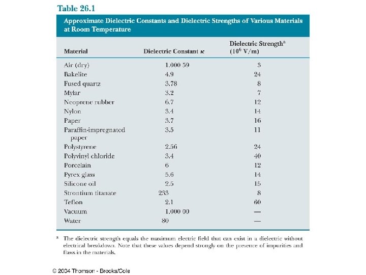
Dielectrics, cont • In theory, d could be made very small to create a very large capacitance • In practice, there is a limit to d – d is limited by the electric discharge that could occur though the dielectric medium separating the plates • For a given d, the maximum voltage that can be applied to a capacitor without causing a discharge depends on the dielectric strength of the material
Dielectrics, final • Dielectrics provide the following advantages: – Increase in capacitance – Increase the maximum operating voltage – Possible mechanical support between the plates • This allows the plates to be close together without touching • This decreases d and increases C
Types of Capacitors – Tubular • Metallic foil may be interlaced with thin sheets of paper or Mylar • The layers are rolled into a cylinder to form a small package for the capacitor
Types of Capacitors – Oil Filled • Common for highvoltage capacitors • A number of interwoven metallic plates are immersed in silicon oil
Types of Capacitors – Electrolytic • Used to store large amounts of charge at relatively low voltages • The electrolyte is a solution that conducts electricity by virtue of motion of ions contained in the solution
Types of Capacitors – Variable • Variable capacitors consist of two interwoven sets of metallic plates • One plate is fixed and the other is movable • These capacitors generally vary between 10 and 500 p. F • Used in radio tuning circuits
Electric Dipole • An electric dipole consists of two charges of equal magnitude and opposite signs • The charges are separated by 2 a • The electric dipole moment (p) is directed along the line joining the charges from –q to +q
Electric Dipole, 2 • The electric dipole moment has a magnitude of p = 2 aq • Assume the dipole is placed in a uniform external field, E – E is external to the dipole; it is not the field produced by the dipole • Assume the dipole makes an angle θ with the field
Electric Dipole, 3 • Each charge has a force of F = Eq acting on it • The net force on the dipole is zero • The forces produce a net torque on the dipole
Electric Dipole, final • The magnitude of the torque is: t = 2 Fa sin θ = p. E sin θ • The torque can also be expressed as the cross product of the moment and the field: t=px. E • The potential energy can be expressed as a function of the orientation of the dipole with the field: Uf – Ui = p. E(cos θi – cos θf) ® U = - p. E cos θ = - p · E
Polar vs. Nonpolar Molecules • Molecules are said to be polarized when a separation exists between the average position of the negative charges and the average position of the positive charges • Polar molecules are those in which this condition is always present • Molecules without a permanent polarization are called nonpolar molecules
Water Molecules • A water molecule is an example of a polar molecule • The center of the negative charge is near the center of the oxygen atom • The x is the center of the positive charge distribution
Polar Molecules and Dipoles • The average positions of the positive and negative charges act as point charges • Therefore, polar molecules can be modeled as electric dipoles
Induced Polarization • A symmetrical molecule has no permanent polarization (a) • Polarization can be induced by placing the molecule in an electric field (b) • Induced polarization is the effect that predominates in most materials used as dielectrics in capacitors
Dielectrics – An Atomic View • The molecules that make up the dielectric are modeled as dipoles • The molecules are randomly oriented in the absence of an electric field
Dielectrics – An Atomic View, 2 • An external electric field is applied • This produces a torque on the molecules • The molecules partially align with the electric field
Dielectrics – An Atomic View, 3 • The degree of alignment of the molecules with the field depends on temperature and the magnitude of the field • In general, – the alignment increases with decreasing temperature – the alignment increases with increasing field strength
Dielectrics – An Atomic View, 4 • If the molecules of the dielectric are nonpolar molecules, the electric field produces some charge separation • This produces an induced dipole moment • The effect is then the same as if the molecules were polar
Dielectrics – An Atomic View, final • An external field can polarize the dielectric whether the molecules are polar or nonpolar • The charged edges of the dielectric act as a second pair of plates producing an induced electric field in the direction opposite the original electric field
Induced Charge and Field • The electric field due to the plates is directed to the right and it polarizes the dielectric • The net effect on the dielectric is an induced surface charge that results in an induced electric field • If the dielectric were replaced with a conductor, the net field between the plates would be zero
Geometry of Some Capacitors
Capacitors Energy Stored by a Capacitor
Energy Stored • Suppose we wish to charge a capacitor. • The work done moving a differential amount of charge to the capacitor at a potential of V is: • If we rewrite the potential in terms of the capacitance we get:
Energy Stored cont. • We now integrate to get the total work done in moving the charges.
Energy Stored cont. • If we define the potential energy of an uncharged capacitor to be zero, then W is equal to the potential energy of the charged capacitor.
Energy • The energy stored by a capacitor is equal to the work done in placing charges on the plates of the capacitor. • The work is equal to the average potential difference multiplied by the charge. • Since the average potential is half of the final potential, then it follows that:
Energy of a Capacitor
Example • Two capacitors are identical, except that one is empty and the other is filled with a dielectric of 4. 50. • The empty capacitor is connected to a 12. 0 V battery. • What must the potential difference across the plates of the other capacitor be such that it stores the same amount of electrical energy as the empty capacitor?
Solution • The energy is the same for both capacitors. • The only difference is the potentials and the dielectric constant. • Therefore, we can write the following: