Introduction to Electronics www infonics co nrelectronics 1

- Slides: 87
Introduction to Electronics www. infonics. co. nr/electronics 1
Contents Evolution of Electronics, Impact of Electronics in industry and in society. Resistors- types, specifications. Standard values, marking, colour coding. Capacitors: types, specifications. Standard values, marking, colour coding. Inductors- types, specifications, Principle of working. Transformers: types, specifications, Principle of working. Electro mechanical components: relays and contactors. www. infonics. co. nr/electronics 2
Electronics ? ? ? Branch of science that deals with study of flow & control of electrons study of their behavior & effects in vacuums, gases, and semiconductors, and with devices using such electrons. www. infonics. co. nr/electronics 3
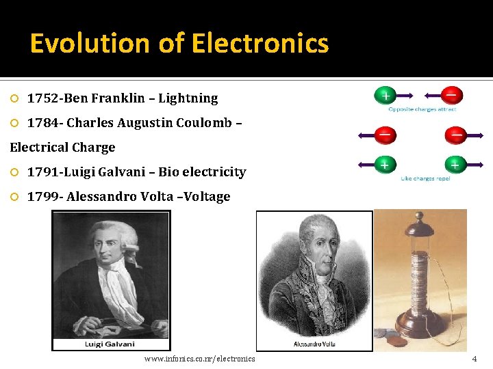
Evolution of Electronics 1752 -Ben Franklin – Lightning 1784 - Charles Augustin Coulomb – Electrical Charge 1791 -Luigi Galvani – Bio electricity 1799 - Alessandro Volta –Voltage www. infonics. co. nr/electronics 4
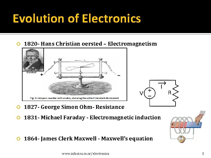
Evolution of Electronics 1820 - Hans Christian oersted – Electromagnetism 1827 - George Simon Ohm- Resistance 1831 - Michael Faraday - Electromagnetic induction 1864 - James Clerk Maxwell - Maxwell’s equation www. infonics. co. nr/electronics 5
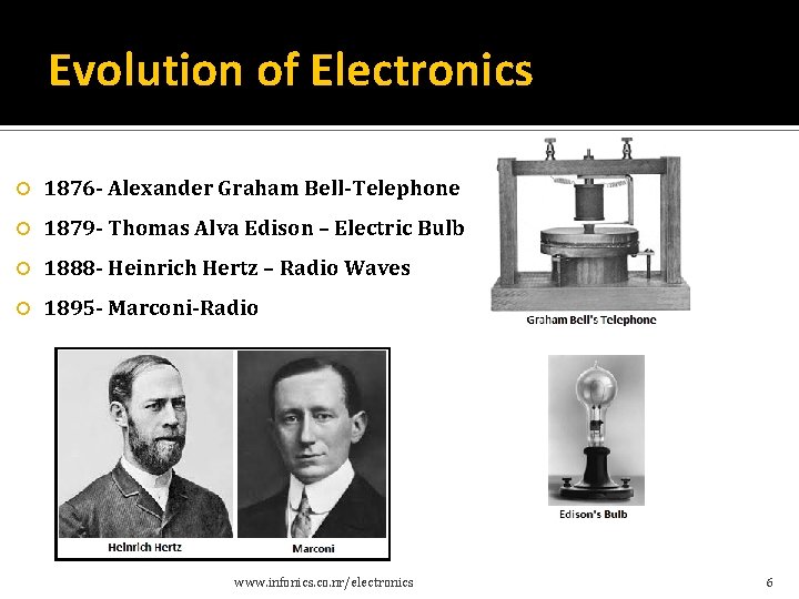
Evolution of Electronics 1876 - Alexander Graham Bell-Telephone 1879 - Thomas Alva Edison – Electric Bulb 1888 - Heinrich Hertz – Radio Waves 1895 - Marconi-Radio www. infonics. co. nr/electronics 6
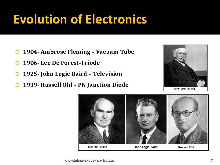
Evolution of Electronics 1904 - Ambrose Fleming – Vacuum Tube 1906 - Lee De Forest-Triode 1925 - John Logie Baird – Television 1939 - Russell Ohl – PN Junction Diode www. infonics. co. nr/electronics 7
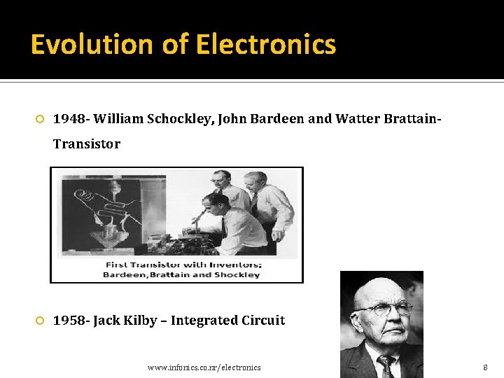
Evolution of Electronics 1948 - William Schockley, John Bardeen and Watter Brattain- Transistor 1958 - Jack Kilby – Integrated Circuit www. infonics. co. nr/electronics 8
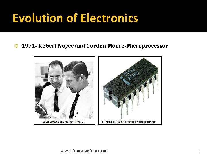
Evolution of Electronics 1971 - Robert Noyce and Gordon Moore-Microprocessor www. infonics. co. nr/electronics 9
Impact of Electronics in industry and in society www. infonics. co. nr/electronics 10
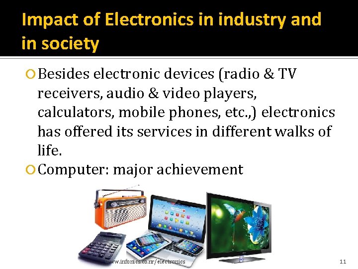
Impact of Electronics in industry and in society Besides electronic devices (radio & TV receivers, audio & video players, calculators, mobile phones, etc. , ) electronics has offered its services in different walks of life. Computer: major achievement www. infonics. co. nr/electronics 11
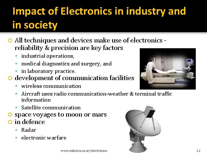
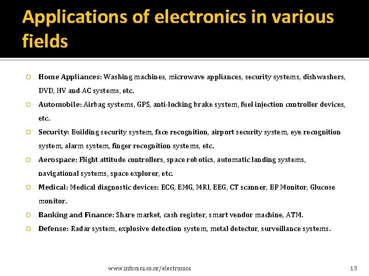
Impact of Electronics in industry and in society All techniques and devices make use of electronics - reliability & precision are key factors industrial operations, medical diagnostics and surgery, and in laboratory practice. development of communication facilities wireless communication Aircraft uses radio communication-weather & terminal traffic information Satellite communication space voyages to moon or mars in defence Radar electronic warfare www. infonics. co. nr/electronics 12
Applications of electronics in various fields Home Appliances: Washing machines, microwave appliances, security systems, dishwashers, DVD, HV and AC systems, etc. Automobile: Airbag systems, GPS, anti-locking brake system, fuel injection controller devices, etc. Security: Building security system, face recognition, airport security system, eye recognition system, alarm system, finger recognition systems, etc. Aerospace: Flight attitude controllers, space robotics, automatic landing systems, navigational systems, space explorer, etc. Medical: Medical diagnostic devices: ECG, EMG, MRI, EEG, CT scanner, BP Monitor, Glucose monitor. Banking and Finance: Share market, cash register, smart vendor machine, ATM. Defense: Radar system, explosive detection system, metal detector, surveillance systems. www. infonics. co. nr/electronics 13
Introduction to Electronic Components www. infonics. co. nr/electronics 14
Electronic Components-Classification Passive components Not capable of processing an electrical signal such as amplification, oscillation, modulation etc. Aid the active components in functioning. Store or maintain Energy in the form of Voltage or Current. The behavior of passive components is linear. Examples: resistor, capacitor, inductor etc. Active components Capable of processing an electrical signal such as amplification, oscillation, modulation etc. Produces energy in the form of Voltage or Current. The behavior of active components is nonlinear. Examples: transistors and diodes. www. infonics. co. nr/electronics 15
Introduction to Passive Components Resistors www. infonics. co. nr
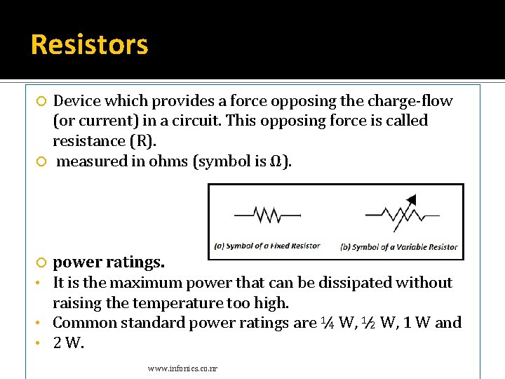
Resistors Device which provides a force opposing the charge-flow (or current) in a circuit. This opposing force is called resistance (R). measured in ohms (symbol is Ω). power ratings. It is the maximum power that can be dissipated without raising the temperature too high. • Common standard power ratings are ¼ W, ½ W, 1 W and • 2 W. • www. infonics. co. nr
Resistors-Types Two basic types of resistors. Linear Resistors Non Linear Resistors values change with the applied voltage and temperature which current value is directly proportional to the applied voltage Two types of linear resistors: a) Fixed Resistors b) Variable Resistors. Fixed Resistors specific value and we can’t change the value. Types of Fixed resistors. Ø Ø Carbon Composition Resistors Wire Wound Resistors Thin Film Resistors Thick Film Resistors www. infonics. co. nr
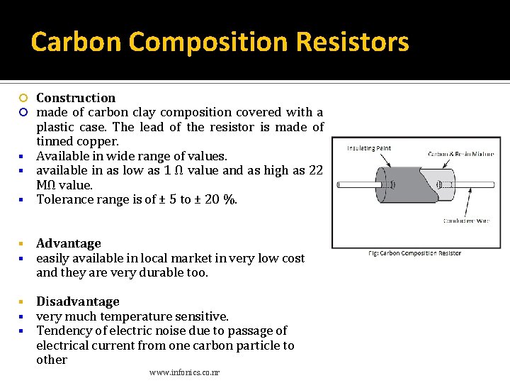
Carbon Composition Resistors Construction made of carbon clay composition covered with a plastic case. The lead of the resistor is made of tinned copper. Available in wide range of values. available in as low as 1 Ω value and as high as 22 MΩ value. Tolerance range is of ± 5 to ± 20 %. Advantage easily available in local market in very low cost and they are very durable too. Disadvantage very much temperature sensitive. Tendency of electric noise due to passage of electrical current from one carbon particle to other www. infonics. co. nr
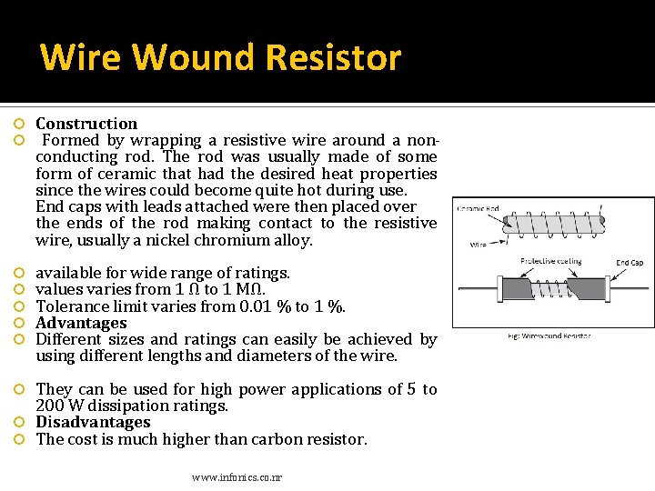
Wire Wound Resistor Construction Formed by wrapping a resistive wire around a nonconducting rod. The rod was usually made of some form of ceramic that had the desired heat properties since the wires could become quite hot during use. End caps with leads attached were then placed over the ends of the rod making contact to the resistive wire, usually a nickel chromium alloy. available for wide range of ratings. values varies from 1 Ω to 1 MΩ. Tolerance limit varies from 0. 01 % to 1 %. Advantages Different sizes and ratings can easily be achieved by using different lengths and diameters of the wire. They can be used for high power applications of 5 to 200 W dissipation ratings. Disadvantages The cost is much higher than carbon resistor. www. infonics. co. nr
Thin Film Resistors Construction A very thin conducting material layer overlaid on insulating rod, plate or tube which is made from high quality ceramic material or glass. Types of thin film resistors. Metal Film Resistor. Carbon Film Resistor. www. infonics. co. nr
Metal Film and Carbon Film Resistor Construction constructed by means of film deposition technique; deposition a thin film of resistible material such as pure carbon or metal on to an insulating core. Metallic contact cap is fitted at both ends of the resistor. The caps must be in contact with resistible film. The lead wires are welded to these end caps. Advantages can be made up to a value of 10, 000 MΩ size of this type of resistor is much smaller than wire wound resistor. www. infonics. co. nr
Thick Film Resistors Construction same like thin film resistors, but the difference is that there is a thick film instead of a thin film or layer of resistive material around. Two types of thick film resistors. Metal Oxide Resistors Cermet Oxide Resistors Fusible Resistors www. infonics. co. nr
Fusible Resistors Construction Same like a wire wound resistor. When a circuit power rating increased than the specified value, then this resistor is fused, i. e. it breaks or open the circuit. That’s why it is called Fusible resistors perform double jobs means they limit the current as well as it can be used as a fuse. They used widely in TV Sets, Amplifiers, and other expensive electronic circuits. Generally, the ohmic value of fusible resistors is less than 10 Ohms. www. infonics. co. nr
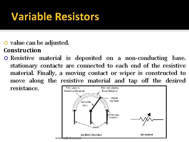
Variable Resistors value can be adjusted. Construction Resistive material is deposited on a non-conducting base. stationary contacts are connected to each end of the resistive material. Finally, a moving contact or wiper is constructed to move along the resistive material and tap off the desired resistance. www. infonics. co. nr
Non Linear Resistors current flowing through it does not change according to Ohm’s Law but, changes with change in temperature or applied voltage. flowing current through a resistor changes with change in body temperature-Thermisters. flowing current through a resistor change with the applied voltages. Varistors or VDR (Voltage Dependent Resistors). Flowing current through a resistor change with the light falling on it. Photo Resistor Different types of Non Linear Resistors. 1. Thermisters 2. Varisters(VDR) 3. Photo Resistor or Photo Conductive Cell or LDR www. infonics. co. nr
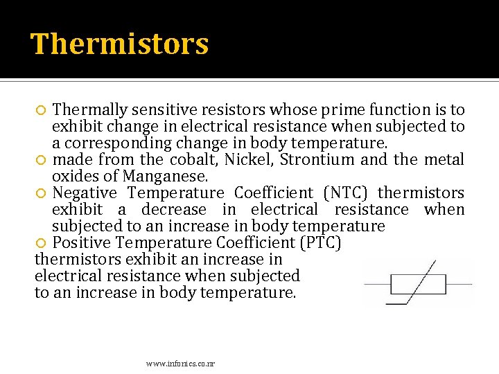
Thermistors Thermally sensitive resistors whose prime function is to exhibit change in electrical resistance when subjected to a corresponding change in body temperature. made from the cobalt, Nickel, Strontium and the metal oxides of Manganese. Negative Temperature Coefficient (NTC) thermistors exhibit a decrease in electrical resistance when subjected to an increase in body temperature Positive Temperature Coefficient (PTC) thermistors exhibit an increase in electrical resistance when subjected to an increase in body temperature. www. infonics. co. nr
Varistors flowing current through a resistor change with the applied voltages-Varistors or VDR (Voltage Dependent Resistors). used to protect circuits from destructive voltage spikes. www. infonics. co. nr
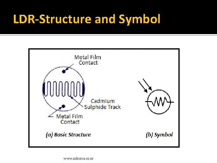
Photo Resistor or Photo Conductive Cell or LDR (Light Dependent Resistors) Resistance value changes with light intensity. The material which is used to make these kinds of resistors is called photo conductors, e. g. cadmium sulfide, lead sulfide etc. When light falls on the photoconductive cells (LDR or Photo resistor), then there is an increase in the free carriers (electron hole pairs) due to light energy, which reduce the resistance of semiconductor material (i. e. the quantity of light energy is inversely proportional to the semiconductor material). It means photo resistors have a negative temperature coefficient. www. infonics. co. nr
LDR-Structure and Symbol www. infonics. co. nr
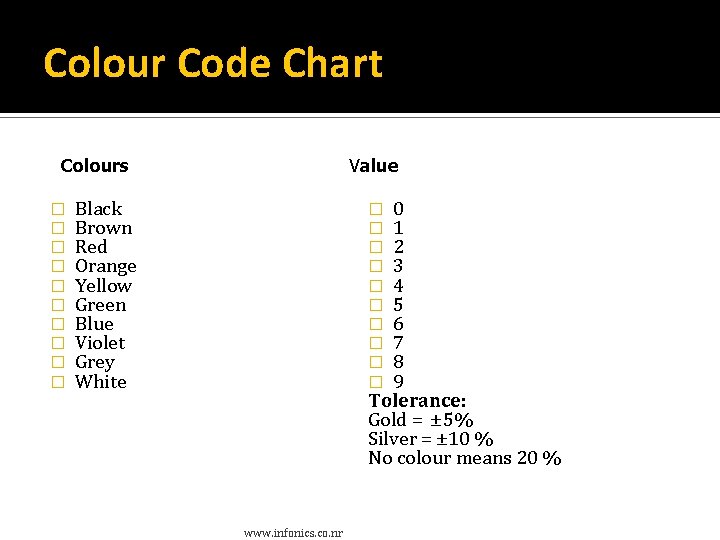
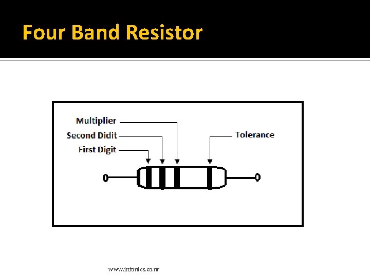
Resistor Marking 4 -band resistors First two bands identify the first and second digits of the resistance value, and the third band indicates the number of zeroes. The fourth determines the tolerance. 5 -band resistors First three bands provide the first three digits of the resistor value. The third band is only used when the tolerance of the resistor is less than 2%. The fourth gives the multiplier. The fifth indicates the tolerance of the resistor. 6 -band resistors First five bands have the same meaning as the 5 -band resistors. The sixth band is a temperature coefficient that indicates the change in electrical conductivity with temperature. www. infonics. co. nr
Colour Code Chart Colours � � � � � Value Black Brown Red Orange Yellow Green Blue Violet Grey White 0 1 2 3 4 5 6 7 8 9 Tolerance: Gold = ± 5% Silver = ± 10 % No colour means 20 % � � � � � www. infonics. co. nr
Four Band Resistor www. infonics. co. nr
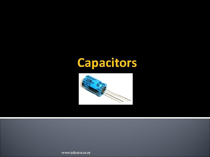
Capacitors www. infonics. co. nr
Capacitor simple passive element that is used to ‘store electricity’. a component which has the ability or ‘capacity’ to store energy in the form of an electrical charge producing a potential difference across its plates, much like a small rechargeable battery. www. infonics. co. nr
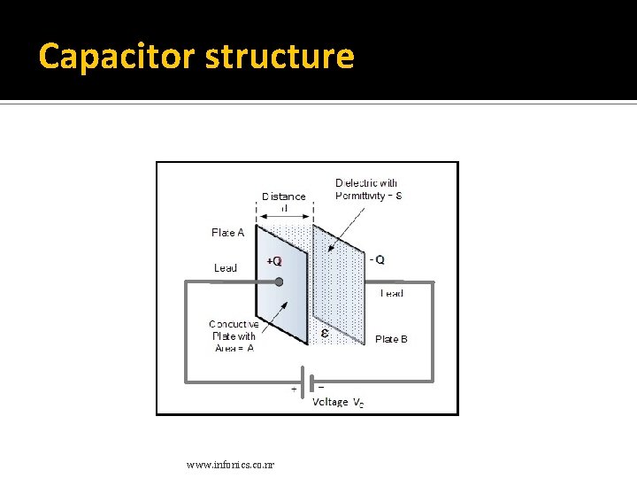
Capacitor-Structure consists of two or more parallel conductive plates which are not connected or touching each other, but are electrically separated either by air or by some form of a good insulating material such as waxed paper, mica, ceramic, plastic or some form of a liquid gel as used in electrolytic capacitors. The insulating layer between capacitor plates is commonly called the Dielectric. www. infonics. co. nr
Capacitor structure www. infonics. co. nr
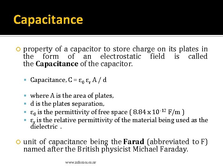
Capacitance property of a capacitor to store charge on its plates in the form of an electrostatic field is called the Capacitance of the capacitor. Capacitance, C = ε 0 εr A / d where A is the area of plates, d is the plates separation, ε 0 is the permittivity of free space ( 8. 84 x 10 -12 F/m ) εr is the relative permittivity of the material being used as the dielectric . unit of capacitance being the Farad (abbreviated to F) named after the British physicist Michael Faraday. www. infonics. co. nr
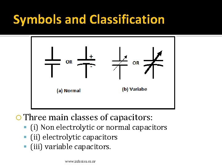
Symbols and Classification Three main classes of capacitors: (i) Non electrolytic or normal capacitors (ii) electrolytic capacitors (iii) variable capacitors. www. infonics. co. nr
Non electrolytic capacitors Non electrolytic capacitors are mostly of parallel plate type and can have mica, paper, ceramic or polymer as dielectric. Mica Capacitors Ceramic Capacitors Paper Capacitors www. infonics. co. nr
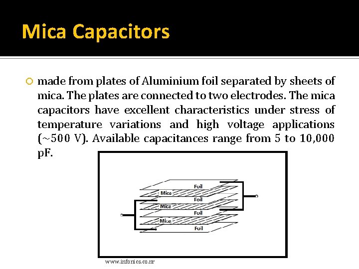
Mica Capacitors made from plates of Aluminium foil separated by sheets of mica. The plates are connected to two electrodes. The mica capacitors have excellent characteristics under stress of temperature variations and high voltage applications (~500 V). Available capacitances range from 5 to 10, 000 p. F. www. infonics. co. nr
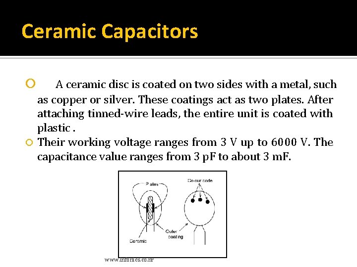
Ceramic Capacitors A ceramic disc is coated on two sides with a metal, such as copper or silver. These coatings act as two plates. After attaching tinned-wire leads, the entire unit is coated with plastic. Their working voltage ranges from 3 V up to 6000 V. The capacitance value ranges from 3 p. F to about 3 m. F. www. infonics. co. nr
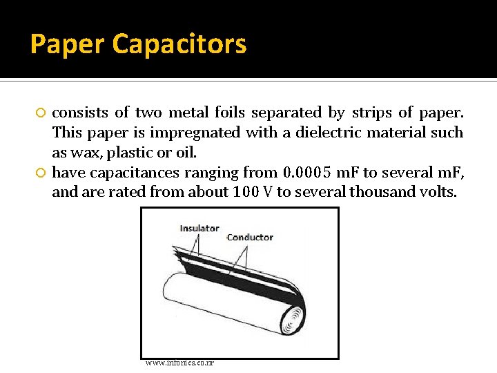
Paper Capacitors consists of two metal foils separated by strips of paper. This paper is impregnated with a dielectric material such as wax, plastic or oil. have capacitances ranging from 0. 0005 m. F to several m. F, and are rated from about 100 V to several thousand volts. www. infonics. co. nr
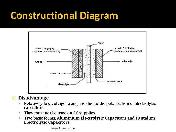
Electrolytic Capacitors Construction Consists of an aluminium-foil electrode which has an aluminium-oxide film covering on one side. The aluminium plate serves as the positive plate and the oxide as the dielectric. The oxide is in contact with a paper or gauze saturated with an electrolyte. The electrolyte forms the second plate (negative) of the capacitor. Another layer of aluminium without the oxide coating is also provided for making electrical contact between one of the terminals and the electrolyte. In most cases, the negative plate is directly connected to the metallic container of the capacitor. The container then serves as the negative terminal for external connections. www. infonics. co. nr
Constructional Diagram Disadvantage Relatively low voltage rating and due to the polarization of electrolytic capacitors. They must not be used on AC supplies. Two basic forms; Aluminium Electrolytic Capacitors and Tantalum Electrolytic Capacitors. www. infonics. co. nr
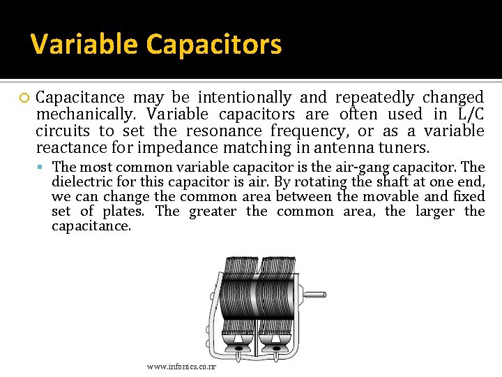
Variable Capacitors Capacitance may be intentionally and repeatedly changed mechanically. Variable capacitors are often used in L/C circuits to set the resonance frequency, or as a variable reactance for impedance matching in antenna tuners. The most common variable capacitor is the air-gang capacitor. The dielectric for this capacitor is air. By rotating the shaft at one end, we can change the common area between the movable and fixed set of plates. The greater the common area, the larger the capacitance. www. infonics. co. nr
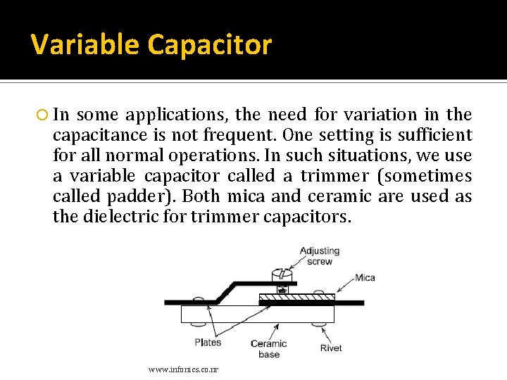
Variable Capacitor In some applications, the need for variation in the capacitance is not frequent. One setting is sufficient for all normal operations. In such situations, we use a variable capacitor called a trimmer (sometimes called padder). Both mica and ceramic are used as the dielectric for trimmer capacitors. www. infonics. co. nr
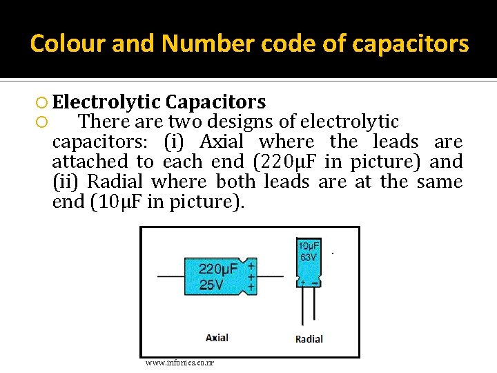
Colour and Number code of capacitors Electrolytic Capacitors There are two designs of electrolytic capacitors: (i) Axial where the leads are attached to each end (220µF in picture) and (ii) Radial where both leads are at the same end (10µF in picture). www. infonics. co. nr
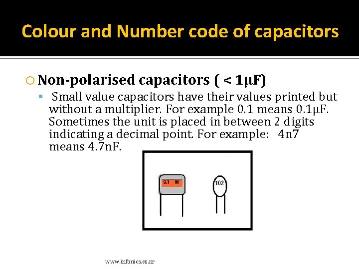
Colour and Number code of capacitors Non-polarised capacitors ( < 1µF) Small value capacitors have their values printed but without a multiplier. For example 0. 1 means 0. 1µF. Sometimes the unit is placed in between 2 digits indicating a decimal point. For example: 4 n 7 means 4. 7 n. F. www. infonics. co. nr
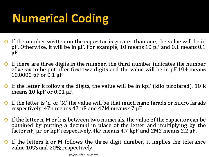
Numerical Coding If the number written on the capacitor is greater than one, the value will be in p. F. Otherwise, it will be in μF. For example, 10 means 10 p. F and 0. 1 means 0. 1 μF. If there are three digits in the number, the third number indicates the number of zeros to be put after first two digits and the value will be in p. F. 104 means 10, 0000 p. F or 0. 1 μF If the letter k follows the digits, the value will be in kp. F (kilo picofarad). 10 k means 10 kp. F or 0. 01 μF. If the letter is ‘n’ or ’M’ the value will be that much nano farads or micro farads respectively. 47 n means 47 n. F and 47 M means 47 μF. If the letter n, M or k is between two numerals, the value of the capacitor can be obtained by putting a decimal in place of the letter and multiplying by the factor n. F, μF or kp. F respectively. 4 k 7 means 4. 7 kp. F and 2 M 2 means 2. 2 μF. If the letters k or M follows the three digit number, it implies the tolerance value 10% and 20% respectively. www. infonics. co. nr
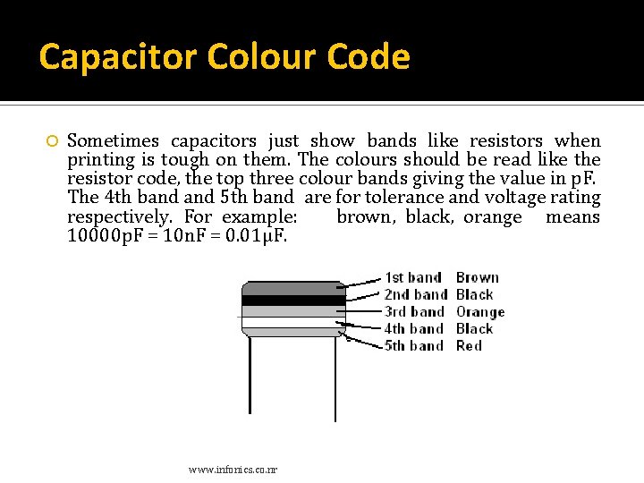
Capacitor Colour Code Sometimes capacitors just show bands like resistors when printing is tough on them. The colours should be read like the resistor code, the top three colour bands giving the value in p. F. The 4 th band 5 th band are for tolerance and voltage rating respectively. For example: brown, black, orange means 10000 p. F = 10 n. F = 0. 01µF. www. infonics. co. nr
Inductors www. infonics. co. nr
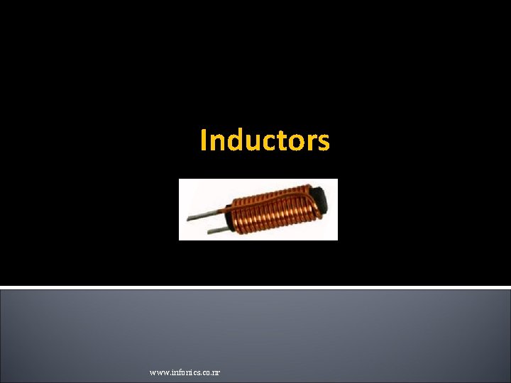
Inductors Passive components consisting of coils of insulated copper wire wound around a former that will have some type of core at its centre. This core might be a metal such as iron that can be easily magnetised; or in high frequency inductors, it will more likely to be just air. A single wire with electricity flowing through it has a small magnetic field around it. When the wire is coiled or looped with one or more turns the magnetic field add together and reinforce the magnetic effect. This magnetic field helps to store the electric current for a short time, even if the supply is removed. When the magnetic field around the coil collapses, the electric current also falls off. Working of an inductor is based on the Faraday’s Laws of Induction. The magnetic field is referred to as magnetic flux. For most coils the current, ( i ) flowing through the coil produces a magnetic flux, ( Nφ ) around it that is proportional to this flow of electrical current. But unlike a Capacitor which opposes a change of voltage across their plates, an inductor opposes the rate of change of current flowing through it due to the build up of self-induced energy within its magnetic field. www. infonics. co. nr
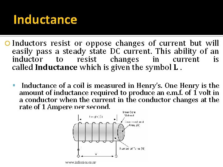
Inductance Inductors resist or oppose changes of current but will easily pass a steady state DC current. This ability of an inductor to resist changes in current is called Inductance which is given the symbol L. Inductance of a coil is measured in Henry’s. One Henry is the amount of inductance required to produce an e. m. f. of 1 volt in a conductor when the current in the conductor changes at the rate of 1 Ampere per second. www. infonics. co. nr
Factors Affecting Inductance. The amount of inductance in an inductor is dependent on: The number of turns of wire in the inductor. The material of the core. The shape and size of the core. The shape, size and arrangement of the wire making up the coils. Applications Inductors are used in many analog circuits and are also used along with capacitors forming filter circuits and thus signal processing. They are also used in Switched Mode Power Supplies (SMPS), oscillators, transmitters, receivers, voltage regulators and also for over voltage protection. www. infonics. co. nr
Types of Inductors have a wide variety and important applications in electronics. Coupled Inductors Coupled inductors are types of inductors that share a magnetic path and influence each other. Coupled inductors are often used as transformers to step up or step down voltage, provide isolated feedback, and in applications where mutual inductance is required. Multi-layer Inductors Multi-layer inductors get their name from the layers of coiled wire that is wound around a central core. Adding additional layers of coiled wire to an inductor increases the inductance but also increases the capacitance between the wires. Molded Inductors that are molded in to a plastic or ceramic housing are known as molded inductors. Generally these inductors have a cylindrical or bar form factor and can be found with several types of winding options. www. infonics. co. nr
Types of Inductors RF Inductors High frequency types of inductors, also called radio frequency or RF inductors, are designed to operate at high frequencies. These inductors often have a higher resistance and lower current rating. Most RF inductors have an air core rather than use a ferrite or other inductance boosting core material due to the increase in losses when those core materials are used which would reduce the operating frequency of the inductor. www. infonics. co. nr
Types of Inductors Chokes A choke is an inductor that is designed to block high frequency pulses while letting lower frequency pulse through. Their names comes from the choking off or blocking of high frequency signals. There are two classes of chokes, power chokes and RF chokes. Power and audio frequency chokes typically have a iron core to increase their inductance and make them more effective filters. RF chokes use iron powder or ferrite beads combined with complex winding patterns to reduce parasitic capacitance and operate effectively at high frequencies. Surface Mount Inductors The push for smaller and more mobile devices has led to the explosion in options for surface mount types of inductors. Surface mount inductors are often used in DC-DC converters, EMI filtering, energy storage, and other applications. Their small size and footprint make surface mount inductors an essential element in the mobile and portable electronic designer's component toolbox. www. infonics. co. nr
Variable Inductor It is formed by moving the magnetic core in and outside of the inductor windings. By this magnetic core we can adjust the inductance value. These types of inductors are used in radio and high frequency applications where the tuning is required. These inductors are typically ranged from 10 μH to 100 μH and in present days these are ranged from 10 n. H to 100 m. H. www. infonics. co. nr
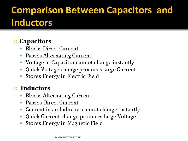
Comparison Between Capacitors and Inductors Capacitors Blocks Direct Current Passes Alternating Current Voltage in Capacitor cannot change instantly Quick Voltage change produces large Current Stores Energy in Electric Field Inductors Blocks Alternating Current Passes Direct Current in an Inductor cannot change instantly Quick Current change produces large Voltage Stores Energy in Magnetic Field www. infonics. co. nr
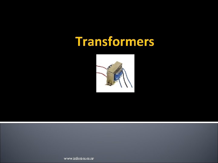
Transformers www. infonics. co. nr
Transformers Static device which transforms electrical energy from one circuit to another without any direct electrical connection and with the help of mutual induction between two windings. It transforms power from one circuit to another without changing its frequency but may be in different voltage level. Transformers are commonly used in applications which require the conversion of AC voltage from one voltage level to another. www. infonics. co. nr
Transformer-classification Two broad categories of transformers: Electronic transformers, which operate at very low power levels, and power transformers, which process thousands of watts of power. Electronic transformers are used in consumer electronic equipment like television sets, CD players, personal computers, and many other devices, to reduce the level of voltage from 220 V (available from the AC mains) to the desired level at which the device operates. Power transformers are used in power generation, transmission and distribution systems to raise or lower the level of voltage to the desired levels. The basic principle of operation of both types of transformers is the same. www. infonics. co. nr
Transformer Construction Need two coils having mutual inductance and a laminated steel core. The two coils are insulated from each other and from the steel core. The device will also need some suitable container for the assembled core and windings, a medium with which the core and its windings from its container can be insulated. www. infonics. co. nr
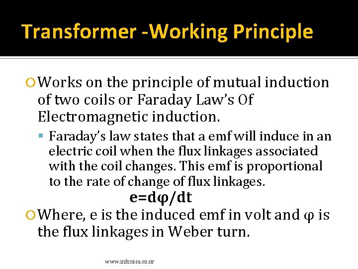
Transformer -Working Principle Works on the principle of mutual induction of two coils or Faraday Law’s Of Electromagnetic induction. Faraday’s law states that a emf will induce in an electric coil when the flux linkages associated with the coil changes. This emf is proportional to the rate of change of flux linkages. e=dφ/dt Where, e is the induced emf in volt and φ is the flux linkages in Weber turn. www. infonics. co. nr
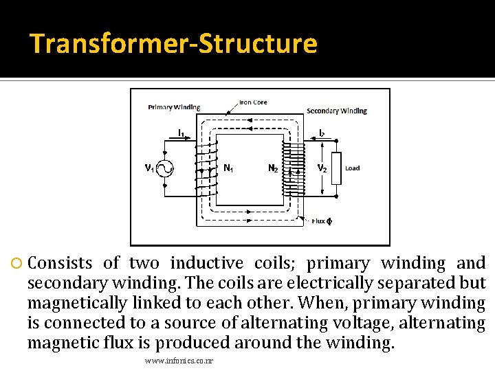
Transformer-Structure Consists of two inductive coils; primary winding and secondary winding. The coils are electrically separated but magnetically linked to each other. When, primary winding is connected to a source of alternating voltage, alternating magnetic flux is produced around the winding. www. infonics. co. nr
Transformer- Structure The core provides magnetic path for the flux, to get linked with the secondary winding. As the flux produced is alternating, emf gets induced in the secondary winding according to Faraday's law of electromagnetic induction. This emf is called 'mutually induced emf', and the frequency of mutually induced emf is same as that of supplied emf. If the secondary winding is closed circuit, then mutually induced current flows through it, and hence the electrical energy is transferred from one circuit (primary) to another circuit (secondary). www. infonics. co. nr
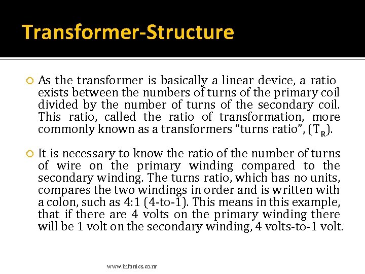
Transformer-Structure As the transformer is basically a linear device, a ratio exists between the numbers of turns of the primary coil divided by the number of turns of the secondary coil. This ratio, called the ratio of transformation, more commonly known as a transformers “turns ratio”, (TR). It is necessary to know the ratio of the number of turns of wire on the primary winding compared to the secondary winding. The turns ratio, which has no units, compares the two windings in order and is written with a colon, such as 4: 1 (4 -to-1). This means in this example, that if there are 4 volts on the primary winding there will be 1 volt on the secondary winding, 4 volts-to-1 volt. www. infonics. co. nr
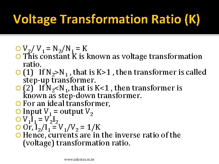
Voltage Transformation Ratio (K) V 2/ V 1 = N 2/N 1 = K This constant K is known as voltage transformation ratio. (1) If N 2>N 1 , that is K>1 , then transformer is called step-up transformer. (2) If N 2<N 1, that is K<1 , then transformer is known as step-down transformer. For an ideal transformer, Input V 1 = output V 2 V 1 I 1 = V 2 I 2 Or, I 2/I 1 = V 1/V 2 = 1/K Hence, currents are in the inverse ratio of the (voltage) transformation ratio. www. infonics. co. nr
Types of Transformers Based on voltage levels, design, Core medium used, winding arrangements and the type of cooling employed. www. infonics. co. nr
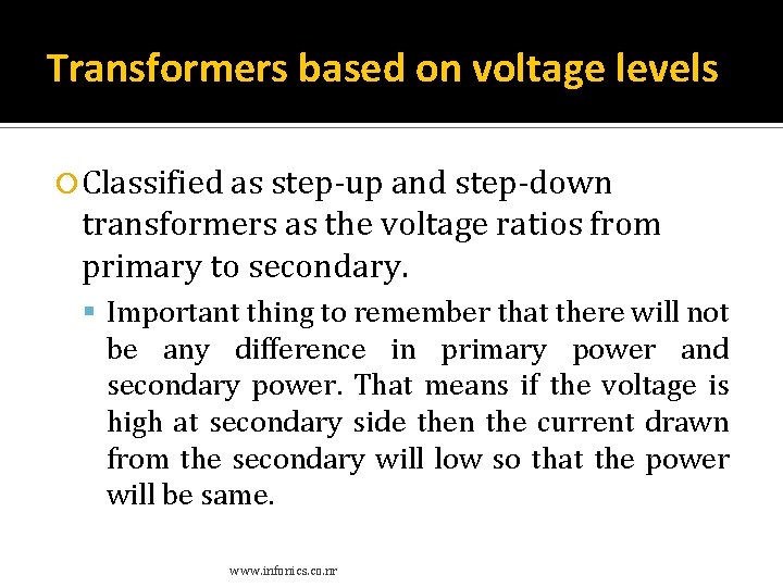
Transformers based on voltage levels Classified as step-up and step-down transformers as the voltage ratios from primary to secondary. Important thing to remember that there will not be any difference in primary power and secondary power. That means if the voltage is high at secondary side then the current drawn from the secondary will low so that the power will be same. www. infonics. co. nr
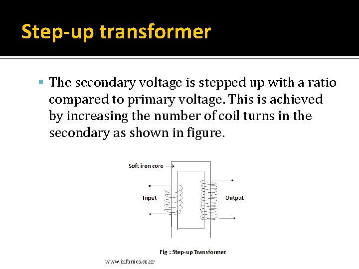
Step-up transformer The secondary voltage is stepped up with a ratio compared to primary voltage. This is achieved by increasing the number of coil turns in the secondary as shown in figure. www. infonics. co. nr
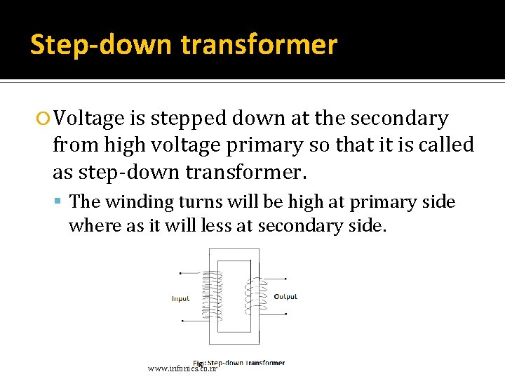
Step-down transformer Voltage is stepped down at the secondary from high voltage primary so that it is called as step-down transformer. The winding turns will be high at primary side where as it will less at secondary side. www. infonics. co. nr
Electromechanical Devices www. infonics. co. nr
Electromechanical Devices which carry out electrical operations by using moving parts are known as electromechanical devices. Devices which involve an electrical signal to create mechanical movement, or mechanical movement to create an electric signal. www. infonics. co. nr
Electromechanical Relays A relay is an electrically operated switch. Many relays use an electromagnet to mechanically operate a switch. Relays are used where it is necessary to control a circuit by a low-power signal or where several circuits must be controlled by one signal. www. infonics. co. nr
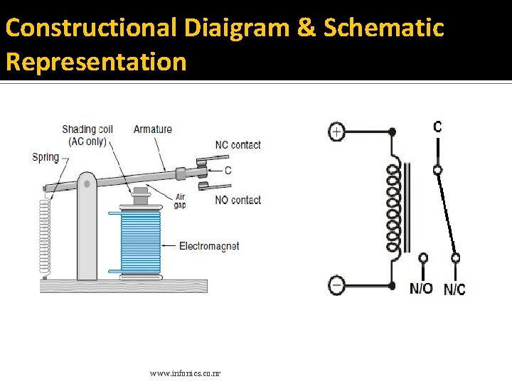
Constructional Diaigram & Schematic Representation www. infonics. co. nr
Relay- Constructional Diagram Relay consists a inductor coil, a spring, Swing terminal (armature), and two high power contacts named as normally closed (N/C) and normally opened (N/O). Relay uses an Electromagnet to move swing terminal between two contacts (N/O and N/C). When there is no power applied to the inductor coil (Relay is OFF), the spring holds the swing terminal is attached to NC contact. Whenever required power is applied to the inductor coil, the current flowing through the coil generates a magnetic field which is helpful to move the swing terminal and attached it to the normally open (NO) contact. Again when power is OFF, the spring restores the swing terminal position to NC. www. infonics. co. nr
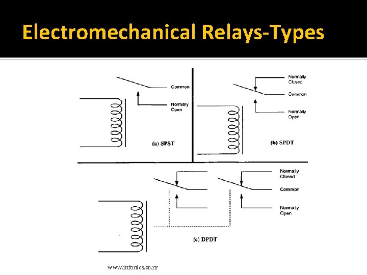
Pole and Throw A switch has at least two terminals: one for the signal to go in and one for the signal to go out. The poles of a switch are the input terminals; these define how many separate circuits the switch can control. The throws of a switch are the output terminals; these define the number of different output connections each switch pole can connect its input to. A relay is said to switch one or more poles. Each pole has contacts that can be thrown in mainly three ways. They are Normally Open Contact (NO) – NO contact is also called a make contact. It closes the circuit when the relay is activated. It disconnects the circuit when the relay is inactive. Normally Closed Contact (NC) – NC contact is also known as break contact. This is opposite to the NO contact. When the relay is activated, the circuit disconnects. When the relay is deactivated, the circuit connects. www. infonics. co. nr
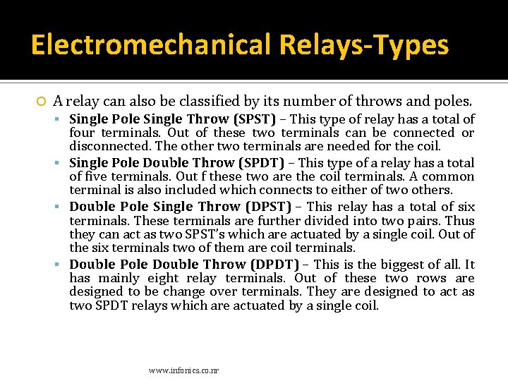
Electromechanical Relays-Types A relay can also be classified by its number of throws and poles. Single Pole Single Throw (SPST) – This type of relay has a total of four terminals. Out of these two terminals can be connected or disconnected. The other two terminals are needed for the coil. Single Pole Double Throw (SPDT) – This type of a relay has a total of five terminals. Out f these two are the coil terminals. A common terminal is also included which connects to either of two others. Double Pole Single Throw (DPST) – This relay has a total of six terminals. These terminals are further divided into two pairs. Thus they can act as two SPST’s which are actuated by a single coil. Out of the six terminals two of them are coil terminals. Double Pole Double Throw (DPDT) – This is the biggest of all. It has mainly eight relay terminals. Out of these two rows are designed to be change over terminals. They are designed to act as two SPDT relays which are actuated by a single coil. www. infonics. co. nr
Electromechanical Relays-Types www. infonics. co. nr
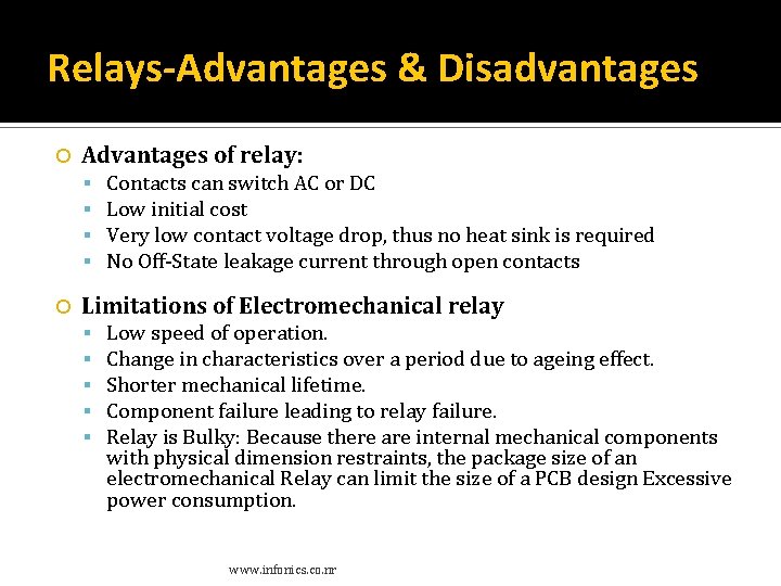
Relays-Advantages & Disadvantages Advantages of relay: Contacts can switch AC or DC Low initial cost Very low contact voltage drop, thus no heat sink is required No Off-State leakage current through open contacts Limitations of Electromechanical relay Low speed of operation. Change in characteristics over a period due to ageing effect. Shorter mechanical lifetime. Component failure leading to relay failure. Relay is Bulky: Because there are internal mechanical components with physical dimension restraints, the package size of an electromechanical Relay can limit the size of a PCB design Excessive power consumption. www. infonics. co. nr
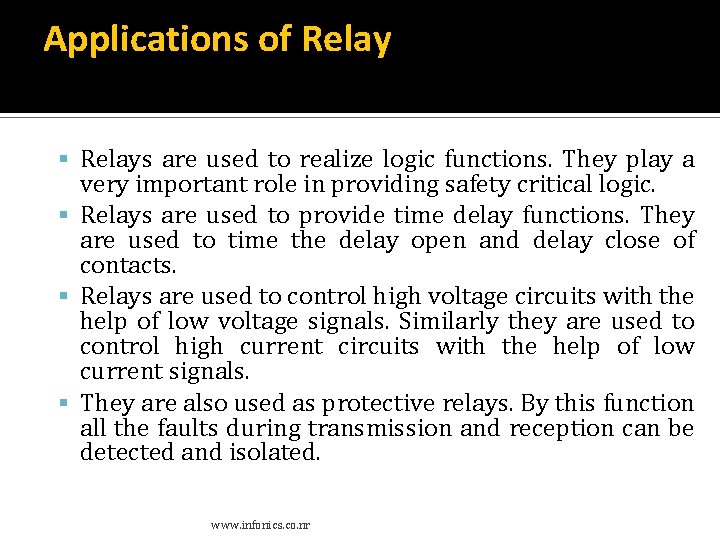
Applications of Relays are used to realize logic functions. They play a very important role in providing safety critical logic. Relays are used to provide time delay functions. They are used to time the delay open and delay close of contacts. Relays are used to control high voltage circuits with the help of low voltage signals. Similarly they are used to control high current circuits with the help of low current signals. They are also used as protective relays. By this function all the faults during transmission and reception can be detected and isolated. www. infonics. co. nr
Contactors When a relay is used to switch a large amount of electrical power through its contacts, it is designated by a special name: contactor. Contactors typically have multiple contacts, and those contacts are usually (but not always) normally-open, so that power to the load is shut off when the coil is de-energized. Perhaps the most common industrial use for contactors is the control of electric motors. www. infonics. co. nr
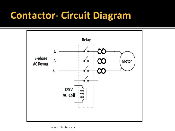
Contactor- Circuit Diagram www. infonics. co. nr
Contactor The top three contacts switch the respective phases of the incoming 3 -phase AC power, typically at least 480 Volts for motors 1 horsepower or greater. The lowest contact is an “auxiliary” contact which has a current rating much lower than that of the large motor power contacts, but is actuated by the same armature as the power contacts. The auxiliary contact is often used in a relay logic circuit, or for some other part of the motor control scheme, typically switching 120 Volt AC power instead of the motor voltage. www. infonics. co. nr
END www. infonics. co. nr/electronics 87