Illumination and Surface Rendering Why Lighting 3 D


 model: determine the color of a surface point")
 Model • To model the interaction of light with surfaces to determine")


 • A surface that is not exposed directly to")


 components.")


- Slides: 63
Illumination and Surface Rendering
Why Lighting? 3 D without lighting 3 D with lighting
3 D without lighting 3 D with lighting 3
“Outline” • Two components: – Lighting Model how we calculate the intensity at a point on the surface – Surface Shading Model Rendering Method - How we calculate the intensity at each pixel
Illumination - the transport of light from a source to a point via direct and indirect paths Lighting – Given a view point, lighting is computing the luminous intensity for a specified 3 D point. Shading - Assigning colors to pixels When we view an opaque non luminous object we see the reflected light from the surface of the object where the total reflected light is the sum of contribution from light source and other reflected surfaces from the scene
Illumination Vs. Shading § Illumination (lighting) model: determine the color of a surface point by simulating some light attributes. § Shading model: applies the illumination models at a set of points and colors the whole image.
Illumination (Lighting) Model • To model the interaction of light with surfaces to determine the final color & brightness of the surface: – Global illumination – Local illumination
Global Illumination • Global Illumination models take into account the interaction of light from all the surfaces in the scene.
Local illumination • Only consider the light, the observer position, and the object material properties Our aim is to do global illumination i. e the transport of light within a scene
What factors play a part in how an object is “lit”? Two components 1. Object Properties – Material – Geometry – Absorption 2. Light Source Properties a. Color (Wavelength(s) of light) b. Shape c. Direction
Object Properties Optical properties of surfaces: Light incident on Opaque Object (Part of it is reflected and part of it absorbed) Material Shiny material Dull material (Reflect more) (Absorb more) Transparent Object (Part of it is reflected and part of it is transmitted
Light Source Properties 1. Color – We usually assume the light has one wavelength 2. Shape – Point Light Source - approximate the light source as a 3 D point in space. Light rays emanate in all directions. • good for small light sources (compared to the scene) e. g far away light sources
Light Source Properties contd… • Light Source Shape continued – Distributed Light Source - approximating the light source as a 3 D object. Light rays usually emanate in specific directions • good for larger light sources e. g area light sources
Light Source Properties contd… 3. Light Source Direction In computer graphics, we usually treat lights as rays emanating from a source. The direction of these rays can either be: 3 a. Omni-directional (point light source) 3 b. Directional (spotlights)
Basic Illumination Model • Simple and fast method for calculating surface intensity or light intensity at a given point. • Lighting calculation are based on: – The background lighting conditions – The light source specification: color, position – Optical properties of surfaces: • Glossy OR matte • Opaque OR transparent (control refection and absorption)
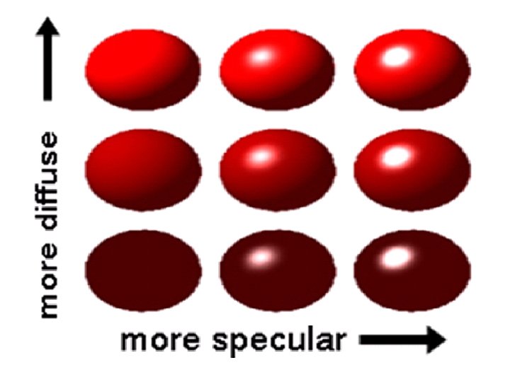
Components of Reflections Ambient – surface exposed to indirect light reflected from nearby objects Diffuse – reflection from incident light with equal intensity in all directions. Depends on surface properties. Specular – The bright spot (specular reflection) shown on a shiny surfaces is the outcome of total reflection of the incident light in a concentrated region
ambient diffuse specular final
Contributions from lights • We will breakdown what a light does to an object into three different components. This APPROXIMATES what a light does. To actually compute the rays is too expensive to do in real -time. • Light at a pixel from a light source = Ambient + Diffuse + Specular contributions Ilight = Iambient + Idiffuse + Ispecular (1)
1. Ambient light (background light) • A surface that is not exposed directly to a light source still will be visible if the nearby object are illuminated i. e due to background/ambient light. • Ambient light has no spatial or directional characteristics. • The amount of ambient light incident on each object is a constant for all surfaces and over all directions.
1. Ambient light Contd…. • Each light source has an ambient light contribution, let Ia. • For a given surface, we can specify how much ambient light the surface can reflect using an ambient reflection coefficient, let Ka (0 < Ka < 1) • So the amount of light that the surface reflect due to ambient light is therefore: Iamb = Ka * Ia (2)
Basic Term The amount of incident light depends on the orientation of the surface relative to the light source direction. Incident light
2. Diffuse Light • Surfaces that are rough or grainy, tend to scatter the reflected light in all directions. This scatter light is called diffuse reflection/ Lambertian reflection. • In this illumination the a surface receives from a light source and reflects equally in all directions. • The brightness of the surface is independent of the observer position (since the light is reflected in all direction equally)
Diffuse light contd. . • Diffuse light is a contribution that a light has on the surface, regardless of viewing direction.
Lambert’s Law Diffuse light contd. . • How much light the surface receives from a light source depends on the angle between its normal and the vector from the surface point to the light (light vector) • Lambert’s law: the radiant energy ’Id’ from a small surface da for a given light source is: (3) I = I * cos( ) d L IL : the intensity of the light source is the angle between the surface normal (N) and light vector (L)
The Diffuse Component Diffuse light contd. . • Surface’s material property: assuming that the surface can reflect Kd (0<Kd<1), diffuse reflection coefficient) amount of diffuse light: (4) I = K * I * cos( ) diff d d d L If N and L are normalized unit vector, then Idiff = Kd * IL * (N. L) (5)
Diffuse light contd. . Examples Sphere diffusely lighted from various angles !
3. Specular Reflection • Specular contribution can be thought of as the “shiny highlight” of a plastic object. OR • These are the bright spots on objects (such as polished metal, apple. . . ) • Light reflected from the surface unequally to all directions. • What is an ideal purely specular reflector? • What does this term depend on? üViewing Direction üNormal of the Surface
Specular Reflection § The result of near total reflection of the incident light in a concentrated region around the specular reflection angle
Snell’s Law Specular reflection applies Snell’s Law. · The incoming ray, the surface normal, and the reflected ray all lie in a common plane. · The angle that the reflected ray forms with the surface normal is determined by the angle that the incoming ray forms with the surface normal, and the relative speeds of light of the mediums in which the incident and reflected rays propagate according to: · We assume l = r
Snell’s Law is for IDEAL surfaces • Think about the amount of light reflected at different angles. N R L V
Specular Reflection for shiny vs. dull objects
Phong’s Model for Specular contd… • As specular reflection from the surface is unequally to all directions -> how much reflection light you can see depends on where you are
Phong’s Model for Specular contd… Approximately the intensity of specular reflection Is is proportional to (cos )shininess Phong Model: - Ispecular = ks. Ilight (cos )shininess = ks. Ilight (V. R)shininess where ks – Specular Coefficient Ilight – Incident light cos (Ø) – Angle between Viewing direction and Reflected ray (6)
Effect of the shininess value
Combining the terms • Ambient - the combination of light reflections from various surfaces to produce a uniform illumination. Background light. • Diffuse - uniform light scattering of light rays on a surface. Proportional to the “amount of light” that hits the surface. Depends on the surface normal and light vector. • Specular - light that gets reflected. Depends on the light ray, the viewing angle, and the surface normal.
Lighting Equation For Single point source: For Multiple point source: Ilambient = light source l’s ambient component Ildiffuse = light source l’s diffuse component Ilspecular = light source l’s specular component kambient = surface material ambient reflectivity kdiffuse = surface material diffuse reflectivity kspecular = surface material specular reflectivity shininess = specular reflection parameter (1 - dull, 100+ very shiny)
Attenuation of light • One factor we have yet to take into account is that a light source contributes a higher incident intensity to closer surfaces. • The energy from a point light source falls off proportional to 1/d 2. • Actually, using only 1/d 2, makes it difficult to correctly light things. Think if d=1? We use:
Contd…. For best we use: Full Illumination Model:
How Colors Get In? Each light source has red, green and blue (RGB) components. Similarly, the ambient, diffuse and specular coefficients of each surface has red, green and blue (RGB) components. Each components of the color is then calculated separately. All final components are then combined to set the final color (RGB) of a point.
Polygon Rendering Methods • Illumination model can be applied at every projected pixel. But it is very expensive. • Shading is how we “color” a polygon with different of different illumination values on its surface.
3 D drawing without rendering results 2 D image. 3 D drawing with rendering obtains depth and perspective impression.
Rendering or Shading Classification There are 3 ways of shading: Ø Constant/ Flat Shading Ø Gouraud Shading Ø Phong Shading Smooth Shading
flat surface rendering • Compute illumination only at one point on the surface and with that color the rest points of polygon. • Flat surface rendering provides accurate display if all the following assumptions are satisfied: – The object is not a curved (smooth) surface (e. g. a polyhedron object) – The light source is very far away (so N. L does not change much across a polygon) – The eye is very far away (so V. R does not change much across a polygon) – The surface is quite small (close to pixel size)
Flat rendering
flat surface rendering Advantage • Fast • Good for some objects Disadvantage • Sudden intensity changes at borders • Shading each polygonal facet individually will not generate an illusion of smooth curved surface
Smooth Shading/Rendering • Need to have per-vertex normal • Gouraud Shading – Interpolate color across triangles/ polygon – Fast, supported by most of the graphics accelerator cards • Phong Shading – Interpolate normal across triangles/ polygon – More accurate, but slow. Not widely supported by hardware
Gouraud Surface Rendering Gouraud surface rendering, called also intensityinterpolation surface rendering, provides smooth color transitions across edges of polygon surfaces. It eliminates the intensity discontinuities occurring in flat rendering.
Gouraud Surface Rendering contd. . 1. Determines normal for each the polygon vertices If we only have per-face normals, the normal at each vertex is the average of the normals of its adjacent faces The normal vector at the vertex V is the average of the polygon normal vectors sharing that point.
Gouraud Surface Rendering contd. . 2. Then apply illumination model at each vertex to obtain color intensities at that position/vertex. 3. Intensity interpolation: linearly interpolate the pixel intensity (color) across a polygon surface Calculate the value of a point based on the distances of the point from it’s two neighbor points If v 1 and v 2 are known, then
Linear Interpolation in a Triangle To determine the intensity/color of point P in the triangle: y 1. determine the intensity of 4 i. e let I 4 by linearly interpolating between intensity I 1 and I 2 of 1 and 2 3 1 Scan-line 4 p 5 2 x
Linear Interpolation in a Triangle contd… To determine the intensity/color of point P in the triangle: y 2. Determine the intensity of 5 i. e let I 5 by linearly interpolating between intensity I 2 and I 3 of 2 and 3 respectively. 3 1 Scan-line 4 p 5 2 x
Linear Interpolation in a Triangle contd… To determine the intensity/color of point P in the triangle: y 3. Determine the intensity of P i. e let Ip by linearly interpolating between intensity I 4 and I 5 of 4 and 5 respectively. or Internal point is interpolated from end points. 3 1 Scan-line 4 p 5 2 x
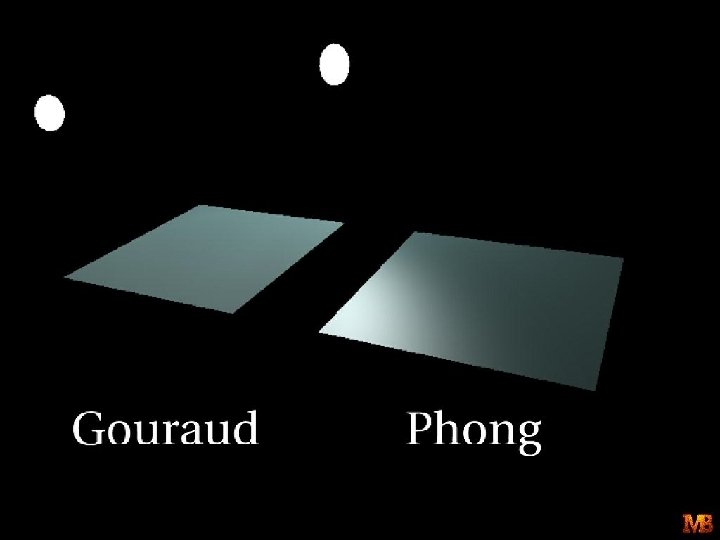
Disadvantage Gouraud rendering may miss specular reflections and also create anomalies of bright or dark bands in image. § Reason: colors are interpolated. Gouraud rendering Accurate rendering
Phong Surface Rendering 1. Instead of interpolating intensities, the average normal vectors at vertices are interpolated. Scan-line y
Phong Surface Rendering 2. Interpolate normal along edges and for each pixel of the scan-lines. (component by component) 3. Compute per-pixel illumination. The computation penalty is that the illumination model is now computed for every point of surface.
Gouraud rendering Phong rendering
Summary of Rendering
Un-lit
Flat Shading
Gouraud Shading
Phong Shading