Ray Tracing Illumination CMSC 435634 Basic Illumination Concepts

Ray Tracing Illumination CMSC 435/634

Basic Illumination Concepts • Terms – Illumination: calculating light intensity at a point (object space; equation) based loosely on physical laws – Shading: algorithm for calculating intensities at pixels (image space; algorithm) • Objects – Light sources: light-emitting – Other objects: light-reflecting • Light sources – Point (special case: at infinity) – Area

Lambert’s Law • Intensity of reflected light related to orientation

Lambert’s Law • Specifically: the radiant energy from any small surface area d. A in any direction relative to the surface normal is proportional to cos

Ambient Light • Additional light bounces we’re not counting • Approximate them as a constant = Amount of extra light coming into this surface = Amount that bounces off of this surface Total extra light bouncing off this surface

Combined Model Adding color: For any wavelength :

Shadows • What if there is an object between the surface and light? 7

Ray Traced Shadows • Trace a ray – Start = point on surface – End = light source – t=0 at Suface, t=1 at Light – “Bias” to avoid surface acne • Test – Bias ≤ t ≤ 1 = shadow – t < Bias or t > 1 = use this light

Mirror Reflection The Dark Side of the Trees - Gilles Tran, Spheres Martin K. B. 9

Ray Tracing Reflection • Viewer looking in direction d sees whatever the viewer “below” the surface sees looking in direction r • In the real world – Energy loss on the bounce – Loss different for different colors • New ray – Start on surface, in reflection direction 10

Calculating Reflection Vector • Angle of of incidence = angle of reflection • Decompose • Recompose

Ray Traced Reflection • Avoid looping forever – Stop after n bounces – Stop when contribution to pixel gets too small

Specular Reflection • Shiny reflection from rough surface • Centered around mirror reflection direction – But more spread more, depending on roughness • Easiest for individual light sources

Specular vs. Mirror Reflection

H vector • Strongest for normal that reflects to • • – One at center of highlight – Zero at 90° • Control highlight width

Combined Specular & Mirror • Many surfaces have both

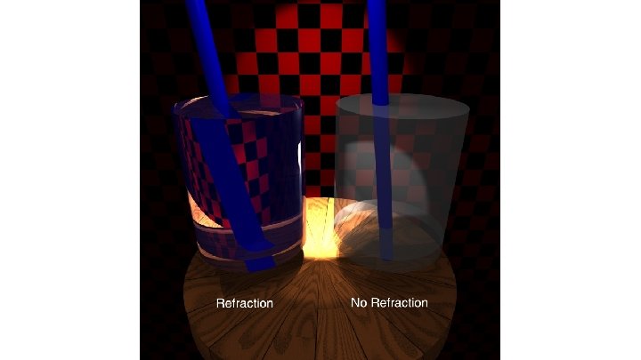
Refraction

Top

Front

Calculating Refraction Vector • Snell’s Law • In terms of • term

Calculating Refraction Vector • Snell’s Law • In terms of • term

Calculating Refraction Vector • Snell’s Law • In terms of and

Alpha Blending • How much makes it through • a = opacity – How much of foreground color 0 -1 • 1 -a = transparency – How much of background color • Foreground*a + Background*(1 -a)

Refraction and Alpha • Refraction = what direction • a = how much – Often approximate as a constant – Better: Use Fresnel – Schlick approximation

Full Ray-Tracing • For each pixel – Compute ray direction – Find closest surface – For each light • Shoot shadow ray • If not shadowed, add direct illumination – Shoot ray in reflection direction – Shoot ray in refraction direction

Motion Blur • Things move while the shutter is open

Ray Traced Motion Blur • Include information on object motion • Spread multiple rays per pixel across time

Depth of Field Soler et al. , Fourier Depth of Field, ACM TOG v 28 n 2, April 2009

Pinhole Lens

Lens Model

Real Lens Focal Plane

Lens Model Focal Plane

Ray Traced DOF • Make sure image plane is at focal plane • Jitter start position within lens aperture – Smaller aperture = closer to pinhole – Larger aperture = more DOF blur
- Slides: 34