Raytracing and Global Illumination R Hoetzlein Rasterization vs

Raytracing and Global Illumination R. Hoetzlein

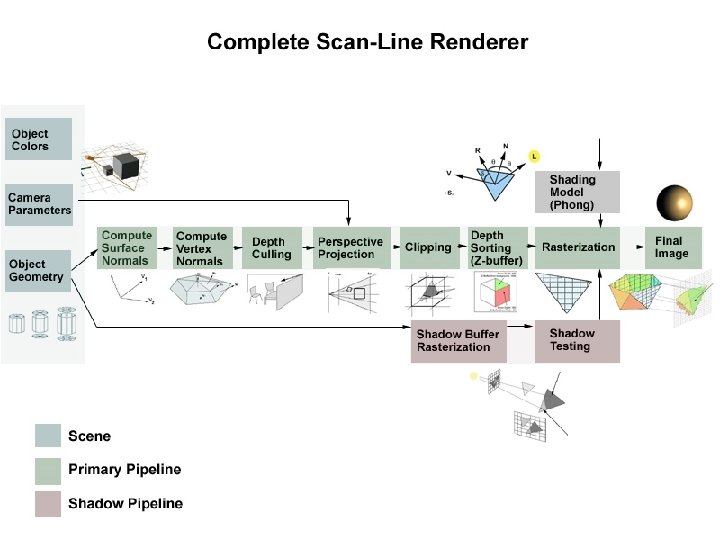
Rasterization vs. Raytracing project cast Rasterize: Raytrace: - Project polygons onto picture plane - Efficient hardware. Open. GL, Direct. X - Cast light rays into scene through picture plane.
 = R 0 + t R")
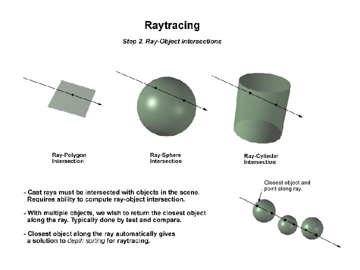
Ray-Sphere Intersection R 0 r p Rdir p(t) = R 0 + t R dir t > 0 p: Ray definition 2 (x – xc)2 + (y – yc)2+ (z – zc) = r 2 Sphere definition Solve for p: At 2 + Bt + C = 0 A = Rx 2 + Ry 2 + Rz 2 B = 2 * (Rx 0–Sx) + Ry (Ry 0 -Sy) + Rz(Rz 0 -Sz) ) 2 2 C = (Rx 0–Sx)2 + (Ry 0–Sy) + (Rz 0–Sz)

Remember: Phong Illumination Model Ambient term Diffuse term Specular term I total Total light received at surface ka I light kd ks Ambient color of surface (RGB vector) Intensity of light source (RGB vector) Diffuse color of surface (RGB vector) Specular color of surface (RGB vector) N L R V Surface normal vector (normalized 3 D) Light direction vector (normalized 3 D) Reflection vector (normalized 3 D) Viewing direction vector (normalized 3 D)

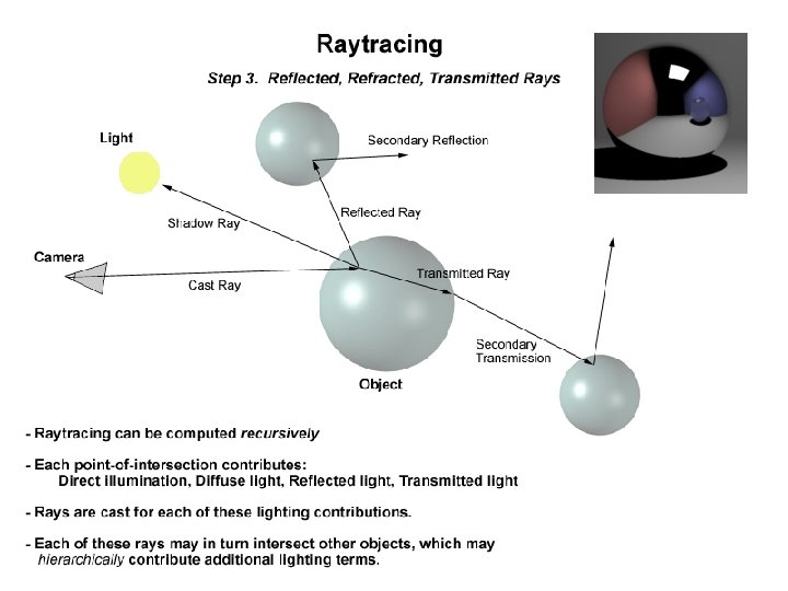
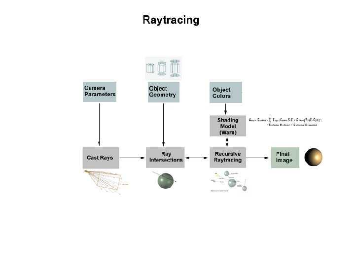
Raytracing Illumination Model - What do we do when we hit an object? -Trace rays to each light source, and also new terms for reflected and refracted light

First application of Raytracing: Rene Descarte, Geometry of Rainbows, 1641 - Rainbows are caused by refraction of light in a spherical water dropplet - Proved that rainbows always occur at 42 degs between viewer & sun

Raytracing - History Turner Whitted An improved illumination model for shaded display Communications of the ACM, v. 23 n. 6, p. 343 -349, June 1980 ABSTRACT To accurately render a two-dimensional image of a three-dimensional scene, global illumination information that affects the intensity of each pixel of the image must be known at the time the intensity is calculated. In a simplified form, this information is stored in a tree of “rays” extending from the viewer to the first surface encountered and from there to other surfaces and to the light sources. Consideration of all of these factors allows the shader to accurately simulate true reflection, shadows, and refraction, as well as the effects simulated by conventional shaders.

Monte Carlo Raytracing - Multiple rays per pixel = Anti-aliasing - Multiple rays per light = Soft shadows - Multiple rays per reflect = Diffuse reflections - Multiple rays per frame = Motion blur
 = clip ( P V M")
Inverse View Matrix p -1 p p’(x, y) = clip ( P V M p(x, y, z) ) = Proj View p p = Cam -1 Proj -1 p’(x, y) T R - Compute ray directions using Inverse Projection and Camera matrix - Loop over all pixels in image. Start with 3 D ray extending from camera

Inverse Projection Matrix x y p - Just draw a line from the origin to the pixel (x, y) - Where else have we see the Inverse Projection Matrix?

What might be some limitations of raytracing?

What might be some limitations of raytracing? 1. Performance 10 million rays, simple scene Monsters, Inc. (Pixar) 13 hours per single frame, most of that is spent ray tracing individual hairs of fur. 2. Light propagation - no caustics 3. Global Illumination – no global diffuse light 4. Memory – All geometry must fit in memory

Raytracing Performance Assume image is: Assume scene is: 1024 x 1024 10, 000 polygons Then there are: 786, 423 pixel, or primary rays Multiply by recursion depth: 5 * 786, 423 = 3. 93 million rays Worst case each ray must check 10, 000 polygons: 3. 9 trillion intersection tests

Geometry is inserted in tree. Acceleration: k-d Tree Rays traverse through it. Special case of BSP Tree. . Axis-aligned BSP Tree


Why is raytracing difficult in GPU shaders? Hint: What is the most complicated part of raytracing?
 2. 4 fps")
GPU Raytracing 16. 3 million rays/sec CPU (AMD 2. 4 ghz) 2. 4 fps GPU (ATI X 1900): 14. 2 fps PS 3 (Cell Proc): 20. 0 fps Free source code 18 x 8 x 4 x Daniel Horn, Jeremy Sugerman, Mike Houston, Pat Hanrahan “Interactive k-D Tree GPU Raytracing”, 2007
 Model a box in Open. GL 2) Model a cylinder in Open.")
Lab 1) Model a box in Open. GL 2) Model a cylinder in Open. GL 3) Coca-Cola challenge 4) Mini-Project 5) Raytracing an arbitrary sphere 6) Other. .
- Slides: 27