HydroElectric Power Plant Introduction One of the most


 Function b) Shape c)")

 Arch dam: It resist the pressure of water partly due to its weight")


 Low head plant • Operating head is less than 15 m. • Vertical")
 Medium head plant • Operating head is less than 15 to 50 m.")
 High head plant • • • Operating head exceed 50 m. Pelton turbines.")


- Slides: 46
Hydro-Electric Power Plant
Introduction: One of the most widely used renewable source of energy for generating electricity on large scale basis is hydropower The power obtained from river or ocean water is called as hydropower. Hydropower is the renewable source of energy since water is available in large quantities from rain, rivers, and oceans and this is will be available for unlimited time to come. 30% of total power of the world is met by hydro-electric power. Total hydro-potential of the world id 5000 GW.
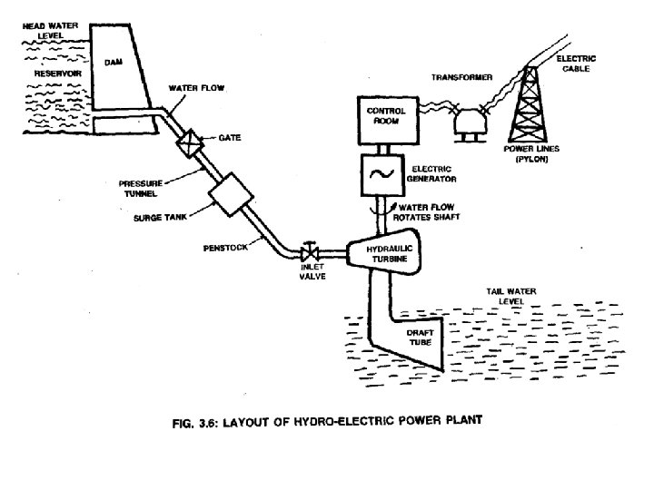
Essential features of Hydro-Electric Power Plant: The essential features of a water power plant are as below: 1. Catchment area. 2. Reservoir. 3. Dam and intake house. 4. water way. 5. Power house. 6. Tail race or outlet water way. 1. Catchment Area. The catchment area of a hydro plant is the whole area behind the dam, draining into a stream or river across which the dam has been built at a suitable place.
2 - Water reservoir: Ø In a reservoir the water collected from the catchment area is stored behind a dam. Ø Catchment area gets its water from rain and streams. Ø The level of water surface in the reservoir is called Head water level. Note : Continuous availability of water is a basic necessity for a hydro -electric power plant. 3 - Dam : ü The purpose of the dam is to store the water and to regulate the out going flow of water. ü The dam helps to store all the incoming water. It also helps to increase the head of the water. In order to generate a required quantity of power it is necessary that a sufficient head is available. 5
• Dam are classified based on following factors: a) Function b) Shape c) Construction material d) Design a) Based on function the dam may be called as storage dam, diversion dam or detention dam. b) Based on the shape the dam may of trapezoidal section & arch type. c) The materials used for constructing dams are earth, rock pieces, stone masonry. d) According to structural design the dam maybe classified as: i. Gravity dam ii. Arch dam iii. Buttress dam
Types of Dam: 1. Masonry Dams. 2. Earth Dams. The masonry dams are of three major classes: a) Gravity dam. b) Buttress dam. c) Arched dam. d) Gravity dam: Resist the pressure of water by its weight. Construction of material used for his dam, is solid masonry or concrete.
b) Arch dam: It resist the pressure of water partly due to its weight and partly due to arch action. c) Buttress dam: • Buttress supporting a flat slab. • When cost of reinforced concrete is high such type of dam is selected.
Spillway: Ø Excess accumulation of water endangers the stability of dam construction. Also in order to avoid the over flow of water out of the dam especially during rainy seasons spillways are provided. This prevents the rise of water level in the dam. Ø Spillways are passages which allows the excess water to flow to a storage area away from the dam. Gate: ü A gate is used to regulate or control the flow of water from the dam. Pressure tunnel: § It is a passage that carries water from the reservoir to the surge tank. 20 February 2021 9
Surge tank: Ø A Surge tank is a small reservoir or tank in which the water level rises or falls due to sudden changes in pressure. Purpose of surge tank: ü To serve as a supply tank to the turbine when the water in the pipe is accelerated during increased load conditions and as a storage tank when the water is decelerating during reduced load conditions. ü To reduce the distance between the free water surface in the dam and the turbine, thereby reducing the water-hammer effect on penstock and also protect the upstream tunnel from high pressure rise. Water-hammer effect : o The water hammer is defined as the change in pressure rapidly above or below normal pressure caused by sudden change in the rate of water flow through the pipe, according to the demand of prime mover i. e. turbine 10
4 - Water Ways. Water ways are the passages, through which the water is conveyed to the turbines from the dam. These may include tunnels, canals, flumes, forebays and penstocks and also surge tanks. A forebay is an enlarged passage for drawing the water from the reservoir or the river and giving it to the pipe lines or canals. 20 February 2021 11
Penstock thickness: •
Number of penstock A hydro Power Plant uses a number of turbine which are to be supplied water through penstock. • To use a single penstock for the whole a plant. • To use on penstock for each turbine separately. • To provide multiple penstock but each penstock supplying water to at least two turbine. Factors for Selecting number of penstocks: • Economy. • Operational safety. • Transportation facilities.
5 - Power House. The power house is a building in which the turbines, alternators and the auxiliary plant are housed. Some important items of equipment provided in the power house are as follows: i. Turbines ii. Generators iii. Governors iv. Relief valve for penstock setting v. Gate valve vi. Transformer vii. Switch board equipment and instruments viii. Oil circuit breaker ix. Storage batteries x. Outgoing connections xi. Cranes xii. Shops & offices
The surface power house has been broadly divided into three subdivisions which is separated from the intake as mentioned below : (a) Substructure ; (b) Intermediate structure ; (c) Super-structure.
Draft tube: v It is connected to the outlet of the turbine. v It allows the turbine to be placed above the tail water level. 6 - Tail water level or Tail race: o Tail water level is the water level after the discharge from the turbine. The discharged water is sent to the river, thus the level of the river is the tail water level. Electric generator, Step-up transformer and Pylon : § As the water rushes through the turbine, it spins the turbine shaft, which is coupled to the electric generator. The generator has a rotating electromagnet called a rotor and a stationary part called a stator. The rotor creates a magnetic field that produces an electric charge in the stator. The charge is transmitted as electricity. The step-up transformer increases the voltage of the current coming from the stator. The electricity is distributed through power lines also called as pylon.
Classification of hydro-Electric power plant The classification of hydro electric power plant depend on the following factors: 1) Quantity of water: It is following types. i. Run of river plant. ii. Storage plant. iii. Pumped storage. 2) a) b) c) Availability of Head of Water: Low head plant. Medium head plant. High head plants Operating head < 15 m. Operating head 15 to 50 m. Operating head > 50 m.
a) Low head plant • Operating head is less than 15 m. • Vertical shaft Francis turbine or Kaplan turbine. • Small dam is required.
a) Medium head plant • Operating head is less than 15 to 50 m. • Francis turbines. • Forebay is provided at the beginning of the penstock.
a) High head plant • • • Operating head exceed 50 m. Pelton turbines. surge tank is attached to the penstock to reduce water hammer effect on the penstock.
Advantages of hydel power plant : Ø Water is a renewable energy source. Ø Maintenance and operation charges are very low. Ø The efficiency of the plant does not change with age. Ø In addition to power generation, hydro-electric power plants are also useful for flood control, irrigation purposes, fishery and recreation. Ø Have a longer life(100 to 125 years) as they operate at atmospheric temperature. Ø Water stored in the hydro-electric power plants can also be used for domestic water supply. Ø Since hydro-electric power plants run at low speeds(300 to 400 rpm) there is no requirement of special alloy steel construction materials or specialised mechanical maintenance.
Disadvantages of hydel power plant : ü The initial cost of the plant is very high. ü Since they are located far away from the load centre, cost of transmission lines and transmission losses will be more. ü During drought season the power production may be reduced or even stopped due to insufficient water in the reservoir. ü Water in the reservoir is lost by evaporation.
Draft Tube: Reaction turbines must be completely enclosed because a pressure difference exists between the working fluid (water) in the turbine and atmosphere. Therefore, it is necessary to connect the turbine outlet by means of a pipe known as draft tube upto tailrace level. Types of Draft Tubes (1) Conical Draft Tube. This is known as tapered draft tube and used in all reaction turbines where conditions permit. It is preferred for low specific speed and vertical shaft Francis turbine. The maximum cone angle of this draft tube is limited to 8° (a = 4°). The hydraulic efficiency of such type of draft tube is 90%.
2 - Elbow Type Draft Tube. The elbow type draft tube is often preferred in most of the power plants, where the setting of vertical draft tube does not permit enough room without excessive cost of excavation. 3 - Moody Draft Tube. This draft tube has an advantage that its conical portion at the center reduces the whirl action of water moving with high velocity centre reduces.
Hydraulic Turbines Advantages: Simple in construction. Easily controllable. Efficient. Ability to work at peak load. Work on load variation. Start from cold conditions & pick up load at short time. Types of turbines: a) Impulse b) Reaction
Impulse Turbine: The passages are not completely filled, water acting on a wheel buckets is at atmospheric pressure and is supplied at few points at the periphery of wheel & kinetic energy is supplied to the wheel. Casing Penstock Nozzle Runner Buckets Needle Valve shaft
Reaction Turbine: Water passages are completely filled with water, water acting on wheel vanes is under pressure greater than atmospheric, water enter all around the periphery of wheel and energy is in the form of both pressure & kinetic energy is utilized by the wheel. Essential parts: Spiral casing Guide wheel Runner Draft tube • Horizontal shaft type or vertical shaft type turbine • Low & medium head turbines
Direction of flow of water: I. III. IV. Tangential flow turbine Radial flow turbine. Axial flow turbine. Mixed flow turbine. Types of turbine Flow direction Kaplan turbine Axial flow Franics Turbine Radial inward or mixed flow Pelton wheel Tangential flow
Position of shaft: I. II. Vertical shaft turbine. Horizontal shaft turbine. Head of water: I. High head turbines. II. Medium head turbines. III. Low head turbines. Impulse turbines Reaction turbines high head. low & medium heads.
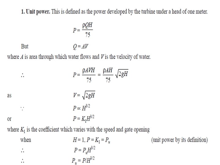
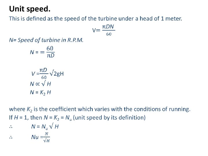
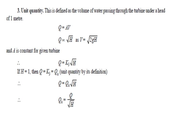
Performance of water turbine: Important parameter for any particular turbine are: • Discharge • Head • Efficiency • Speed • Power The turbine characteristic like unit power, unit speed & unit discharge help in studying the performance of turbines.
Specific Speed: The specific speed of a turbine is defined as the speed at which the turbine runs developing one B. H. P. under a head of one meter. The equation for the specific speed of a turbine can be obtained by using the principle of similarity. where D and N are diameter and speed of a turbine and H is the head acting on the turbine. where B is the height of the blade and Vf is the velocity of flow. Substituting the value of D in the above equation. where P is the power developed.
Substituting the value of Q in the above equation, we get where C is constant depending upon the type of the turbine. If the turbine develops 1 B. H. P. under one meter head then C = N. where Ns is the specific speed as per the definition. Substituting the value of C in the above equation, we get
SELECTION OF SITE FOR A HYDRO-ELECTRIC POWER PLANT The following factors should be given careful consideration while selecting a site for a hydro-electric power plant: 1. Water Available. The recorded observation should be taken over a number of years to know within reasonable, limits the maximum and minimum variations from the average discharge. the river flow data should be based on daily, weekly, monthly and yearly flow ever a number of years. Then the curves or graphs can be plotted between tile river flow and time. These are known as hygrographs and flow duration curves.
2. Water-Storage. The output of a hydropower plant is not uniform due to wide variations of rain fall. To have a uniform power output, a water storage is needed so that excess flow at certain times may be stored to make it available at the times of low flow. To select the site of the Dam, careful study should be made of the geology and topography of the catchment area to see if the natural foundations could be found and put to the best use. 3. Head of Water. The level of water in the reservoir for a proposed plant should always be within limits throughout the year.
4. Distance from Load Center. Most of the time the electric power generated in a hydro-electric power plant has to be used some considerable distance from the site of plant. For this reason, to be economical on transmission of electric power, the routes and the distances should be carefully considered since the cost of erection of transmission lines and their maintenance will depend upon the route selected. 5. Access to Site. It is always a desirable factor to have a good access to the site of the plant. This factor is very important if the electric power generated is to be utilized at or near the plant site. The transport facilities must also be given due consideration.
Hydrology • It is natural science that deal with the distribution of water on land beneath the surface of earth. • It deal with the solid, liquid & vapour forms of water. Hydrologic cycle: The various processes involved in the transfer of moisture from the sea to the land back to the sea again constitute which is called hydrologic cycle. Hydrologic eq. is expressed as follows: P = R + E Where, P = perspiration R = Run-off E = Evaporation.
Perspiration: It includes all the water that falls from atm. To the earth surface. Mostly perspiration is of two types. Liquid perspiration (rainfall) Solid perspiration (Snow, Hail storm) Run-off: It is that portion of the perspiration which makes its way towards stream, lakes or ocean. Run-off occur only if the rate of perspiration exceed the rate at which water infiltrate into the soil & after depression small and large on the soil surface get filled in the water. Evaporation: Transfer of water from liquid to vapour state Transpiration: Process by which water is released to the atmosphere by the plant.
Assignment • Topics: 6. 37 & 6. 38(6. 38. 1, 6. 38. 2, 6. 38. 3, 6. 38. 4) • Examples: • 6. 1 to 6. 13, 6. 15 to 6. 20.
Questions?