DIGITAL RADIOGRAPHY Dr Hussein Ahmed Hassan t i


 Digital")


 plates, the phosphor layer is typically 0. 1 to")


 X-ray")


- Slides: 66
DIGITAL RADIOGRAPHY Dr Hussein Ahmed Hassan
t i v e s D e f i n e t h e t e r m d i
t i v e s C o m p a r e a n d c o n t r a
e r m s Computed radiography DICOM (digital imaging and communications in medicine) Digital imaging Digital radiography Direct capture DR Indirect capture DR Teleradiology
R a d i o g r a p h y M e t h o d i s f i l m b a s
CI o mn av ge en t i Ao cn a ql u i. X sr Drying Xray developer water fixer water
I m a g i n g D i g i t a l i m a g i n g i s a
n t � o f D i g i t a l I m CT coupled imaging devices and the computer. Early CT scanners required hours to produce a single slice. Reconstruction images took several days to produce. First CT scanners imaged the head only.
n M t a �g o n e f t i D c i g i t a l r e s o n a n c e I m i
n F t l �u o o f r o s D c i o g p i i t c a l i m a I g m e
C o n c e p t b e g a n w i t h Digital Radiography Development
E a r l y p r o c e s s i n v o Digital Radiography Development
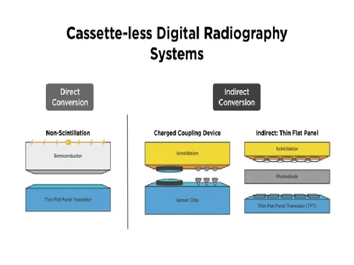
CCD = chargecoupled device, FPD = flat-panel detector, TFT = thin-film transistor. Chart provides a systematic overview of various types of digital detectors.
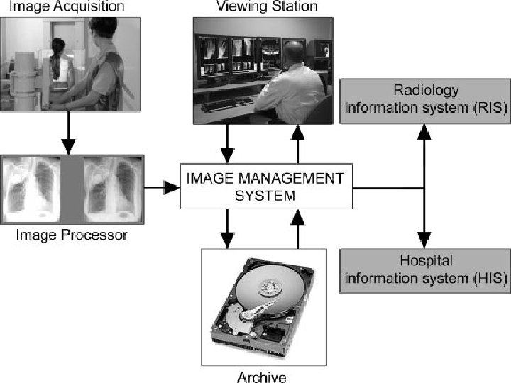
a d i o g r a p h y Uses storage phosphor plates Uses existing equipment Requires special cassettes Requires a special cassette reader Uses a computer workstation and viewing station and a printer
a d i o g r a p h y Storage phosphor plates are similar to intensifying screens. Imaging plate stores x-ray energy for an extended time. Process was first introduced in the United States by Fuji Medical Systems of Japan in 1983. First system used a phosphor storage plate, a reader, and a laser printer.
a d i o g r a p h y M e t h o d w a s s l o w t o
Image Acquisition CR X-ray Tube Latent image Readout Photomultipl ier Erasure ADC IP Ready Fluorescent Workstation
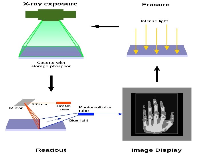
v On photostimulable phosphor (PSP) plates, the phosphor layer is typically 0. 1 to 0. 3 mm thick.
Energy storage v After the initial exposure by typically, X-ray excited electrons enter the conduction band of the crystal and become trapped in the bromine ion empty lattice of the crystal. v These electrons resulting in a metastable state that is higher in energy than the original condition.
Energy release v The release of stored energy within a phosphor by stimulation with visible light, to produce a luminescent signal
v Afterwards, the plates can be "erased, " by exposing the plate to room-intensity white light. Thereby, the plate can be used over and over again. v Imaging plates can theoretically be re-used thousands of times if they are handled carefully and under certain radiation exposure conditions.
Readout of a PSP plate
a d i o g r a p h y C a s s e t t e l e s s s y s t e
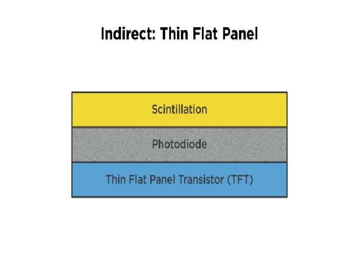
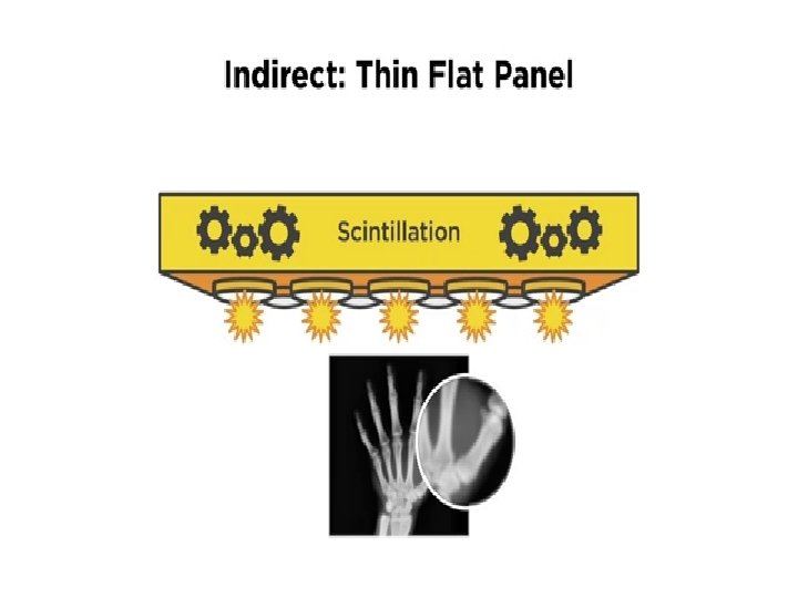
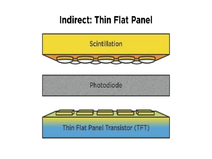
Image Acquisition DR 1. X-ray scintillator bonded to readout ray, thin-film transistor (TFT) X-ray Tube Workstati on Detectors
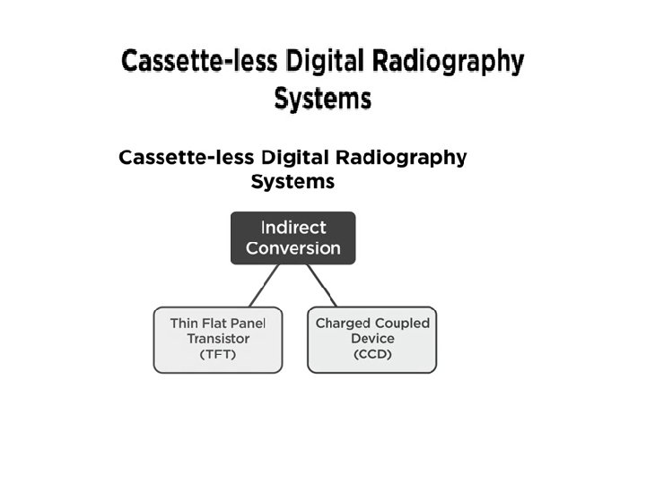
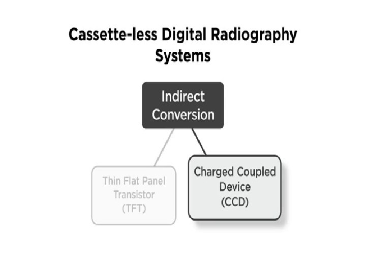
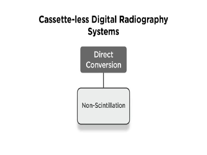
a d i o g r a p h y 1. 2. Two types of digital radiography Indirect capture DR Direct conersion
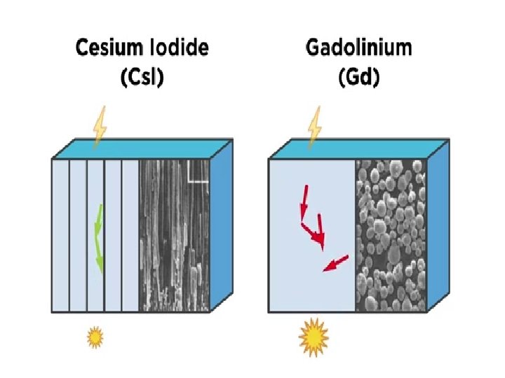
a d i o g r a p h y I n d i r e c t c a p t u r e
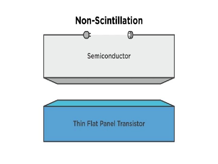
v A photoconductor that converts x-ray photons into electrical charges by setting electrons free v Typical photoconductor materials include amorphous selenium, lead iodide, lead oxide, thallium bromide, and gadolinium compounds
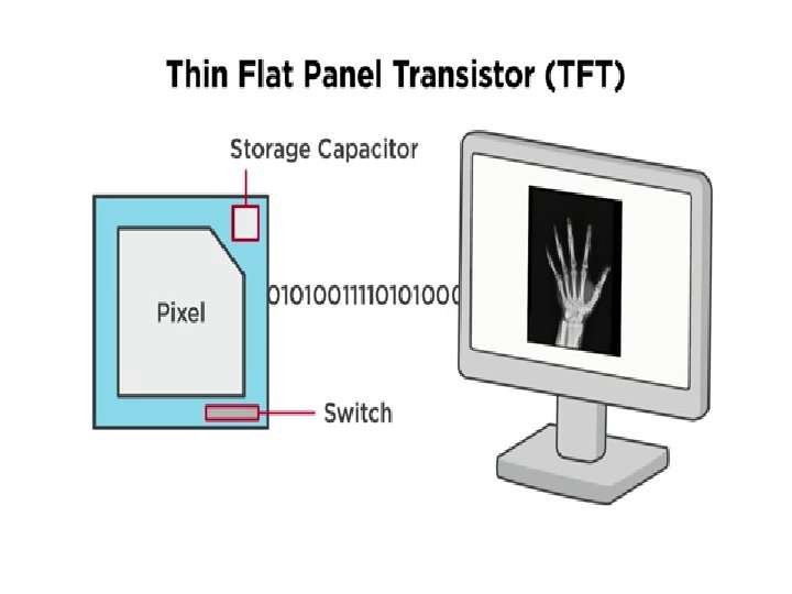
DEL= Dector ELment DEL = charge collecting detector element
Fill Factor The percentage of the pixel face that contains the x-ray detector. Fill factor is approximately 80%
The ability of DEL to produce highb spatial resultion radiograph is desgined by the % of active area within the DLE which is known as Fill Factor.
There dirct relation % of Fill factor and spatial resolution asfill factor increase spatial resoltution increase
A CCD is a light-sensitive sensor for recording images that consists of an integrated circuit containing an array of linked or coupled capacitors.
Charged Couple Device x x in Charged Couple Device there is no photodiode or TFT
Charged Couple Device is connected to Senor through lenses or fiber optics
Optical lenses are needed to reduce the area of the projected light to fit the CCD array
Electrical signal is sent to computer for processing. • Image is viewed on computer screen. •
a d i o g r a p h y D i r e c t c o n e r s i o n n
The semiconuctor is prepared by applyig high voltge electrical charge nono secod before expoure
The interaction between electrical and x-rays cause the semiconductor to release electrical charge
• Electrical signal is sent to computer for processing Image is viewed on computer screen.
a d i o g r a p h y D R u s e d C C D t e c h n o
F o r c o n v e n t i o n a l x Comparison of Film to CR and DR
Comparison of Film to CR and DR Latent image formation is different in CR and DR. Conventional film/screen Film is placed inside of a cassette that contains an intensifying screen. • X-rays strike the intensifying screen, and light is produced. • The light and x-ray photons interact with the silver halide grains in the film emulsion. •
• A n e l e c t r o n i s e j e c t e d f r Comparison of Film to CR and DR
Comparison of Film to CR and DR CR • • • A storage phosphor plate is placed inside of CR cassette. Most storage phosphor plates are made of a barium fluorohalide. When x-rays strike the photosensitive phosphor, some light is given off. Some of the photon energy is deposited within the phosphor particles to create the latent image. The phosphor plate is then fed through the CR reader.
C R , Comparison of Film to CR and DR c o n t i n u e d • F o c u s e
D R • N o c a s s e t t e s a r e Comparison of Film to CR and DR
D R , Comparison of Film to CR and DR c o n t i n u e d • I n d i r e
o c e s s i n g C o n v e n t i o n a l r a d i o g r
C �o o n r v e D n t y i n o a n m a i l c r a R d a i n o
� o r D y n a m i c R a n g CR and DR • • Contain a detector that can respond in a linear manner. Exposure latitude is wide, allowing the single detector to be sensitive to a wide range of exposures. Kilovoltage peak still influences subject contrast, but radiographic contrast is primarily controlled by an image processing look-up table. Milliampere-second setting has more control over image noise, whereas density is controlled by image-processing algorithms.
e n s i t i v i t y I t i s i m p o r t a n t t o 65