Mammography Dr Hussein Ahmed Hassan Mammography Is a


 • The set is designed for a single examination and")


 to")
")

 • In screen-film mammography a separate AEC was required placed")
 device.")


 but this does not give")


, • in which the x-ray")


 • • CAD techniques developed recently for breast cancer The im")

- Slides: 54
Mammography Dr Hussein Ahmed Hassan
Mammography • Is a technique for the radiographic examination of the breast. • This a challenging imaging task since connective tissue, glandular tissue, skin and fat must be visualized but all have very similar attenuation coefficients and thus produce little subject contrast. • Furthermore, it is necessary to image blood vessels, ducts and micro calcifications as small as 100 m diameter.
Types of mammography there are two types of mammography: 1. screening mammogram 2. Workup abnormality mammogram
Image Receptor • Both film/screen and digital receptors are used for mammography. • Each has special characteristics to enhance image quality.
Image Receptor Current x-ray detector technology for mammography
Types of Image Receptor
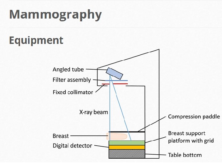
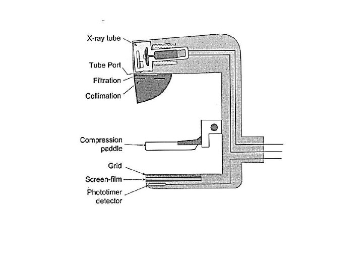
Equipment for Mammography • Equipment for mammography has evolved over at least the last 40 years to the current state of the art. • While there are some differences from one manufacturer to another, there also many characteristics and features that are common to all. • That is what we will introduce here
Angled Tube Head • Due to the anode heel effect, the x-ray beam is not uniform in the direction parallel to the anode-cathode axis of the x-ray tube. • This is used in mammography by aligning the cathode over the chest wall end (thicker area to penetrate, higher energy beam) and the anode over the nipple end (thinner area to penetrate, lower energy beam).
Angled Tube Head When the x-ray tube is tilted in its housing, the effective focal spot is small, the x-ray intensity is more uniform, and tissue against the chest wall is imaged.
C-Arm Design • The x-ray set is a c-arm. The whole gantry rotates so that the tube and breast table remain opposite each other.
Fixed Focus-Detector Distance (FDD) • The set is designed for a single examination and the focus-detector distance (FDD) or focus-to-film distance (FFD) of 65 -66 cm is considered optimum. • This set FDD is a compromise between lower patient doses (lower doses with higher FFDs) and higher film doses (lower exposures with higher FFDs). • Also, higher FDDs require longer exposures for a fixed m. A resulting in more movement unsharpness.
Compression Device • The maximum force applied should be no greater than 200 N (approx. 20 kg weight). • Standard compression forces are normally between 100 - 150 N. • The compression plate is angled so that more of the breast is in contact with the compression paddle.
Compression in mammography has three principal advantages: improved spatial resolution, improved contrast resolution, and lower patient dose.
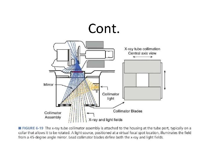
Fixed Field Size • Unlike in general radiography, only one type of examination is done meaning collimation creating fixed field sizes are all that are required
Grids • In mammography, as in general radiography, use of a grid results in improved image contrast at the expense of increased dose to the patient. • Moving anti-scatter grids are used in normal mammography imaging. • For magnification views, the breast support table is above the film to give magnification factors of around 1. 8. In this case the large air gap between the breast and the film works to reduce scatter and so no grid is needed.
Grid • A grid is used in mammography (as in other x-ray procedures) to absorb scattered radiation and improve contrast sensitivity. • Compared to grids for general x-ray imaging, grids for mammography have a lower ratio and the material between the strips is selected for low x-ray absorption. • The grid is contained in a Bucky device that moves it during the x-ray exposure to blur and reduce the visibility of the grid lines.
Anti-Scatter Grids • In mammography, moving grids are used for all contact (broad focus) images. • For magnification images using a fine focal spot size or an air gap technique is used to reduce the amount of scattered radiation reaching the receptor meaning a grid is not required.
HTC Grids • 1. 3: 1 Grid ratio and dose as conventional linear grid • Copper as strips and air interspace A high-transmission cellular grid designed specially for mammography.
Automatic Exposure Control (AEC) • In screen-film mammography a separate AEC was required placed behind the cassette. • With the currently used digital mammography the detectors act as the AEC. • In screen-film radiography an AEC is required to ensure a suitable exposure to prevent under- or over-exposed film. • In digital radiography, however, windowing can negate the effects of unsuitably exposed film and the AEC is more to ensure a suitable radiation dose for the patient and for the working parameters of the digital detector.
The relative position of the automatic exposure control (AEC) device.
Mammogrphy X-ray Tube
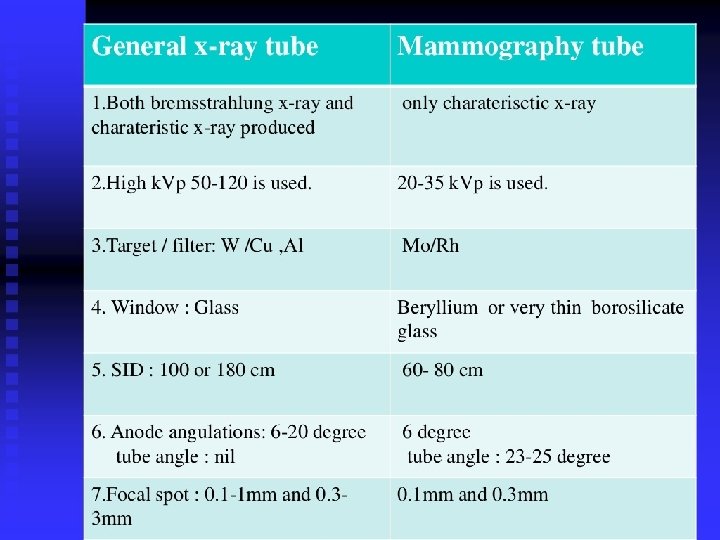
X-ray Tube Anode • Whereas most x-ray tubes use tungsten as the anode material. • Mammography equipment uses molybdenum anodes or in some designs, a dual material anode with an additional rhodium track. • These materials are used because they produce a characteristic radiation spectrum that is close to optimum for breast imaging
Target • Need material that produces characteristic xrays with energies of 17 -20 ke. V (20 -30 ke. V for larger breasts) to produce the best contrast. • The commonly used material is Molybdenum (characteristic x-rays at 17. 5 and 19. 6 ke. V).
Filters • Materials that are placed in the path of x ray beam in order to absorb those x ray with energies above and below the desired spectrum • Whereas most x-ray machines use aluminum or "aluminum equivalent" to filter the x-ray beam to reduce unnecessary exposure to the patient. • Mammography uses filters that work on a different principle and are used to enhance contrast sensitivity. • Molybdenum (same as in the anode) is the standard filter material. • Some systems allow the operator (or automatic control function) to select either the molybdenum or a rhodium filter to optimize the spectrum for specific breast conditions.
Target / filter material • Need good differentiation of low contrast structures • Need very high spatial resolution for microcalcifications
Filter • A filter with a k-edge of an energy just above the characteristic energies is used to remove the higher energy x-ray photons and make the beam as monoenergetic as possible. • Molybdenum has a k-edge of 20 ke. V, just high enough so that the large increase in attenuation (k-edge) doesn't fall into the characteristic energies produced at the molybdenum target.
Alternatives • Mostly Mo. Mo (molybdenum target, molybdenum filter) but this does not give high enough energies for larger breasts. • Rhodium has a k-edge at 23. 3 ke. V and we can use a molybdenum target and rhodium filter (Mo. Rh) to increase the amount of x-rays with energies in the range of 20 - 23. 3 ke. V. • Rhodium characteristic x-rays are at 20. 2 - 22. 7 ke. V. When used as a target this produces a beam with a mean energy that is higher than for Mo. Mo and for Mo. Rh. • Tungsten (W) target and Rhodium filter. The x-ray output is reduced as no characteristic x-rays are produced (and, therefore, longer exposure times) but tungsten is much cheaper. It is mostly used in breasts with implants or that have been treated with radiotherapy as they are much larger and denser. •
X-ray emission spectrum for a molybdenum target x-ray tube with a 30 -μm Mo filter operated at 26 k. Vp. X-ray emission spectrum for a rhodium target x-ray tube with a 50 -μm Rh filter operated at 28 k. Vp.
Emission spectrum from a tungsten target xray tube fltered by molybdenum and rhodium.
A, Un filtered molybdenum x-ray emission spectrum. B, The probability of x-ray absorption in molybdenum. C, Bremsstrahlung x-rays are suppressed and characteristic x-ray emission becomes prominent when a molybdenum target is filtered with molybdenum.
Summary • General use: Mo. Mo • Dense breasts: Mo. Rh or Rh. Rh
Why is molybdenum used in mammography? • The rhodium filter can be used in combination with both the molybdenum and rhodium anodes. . • Molybdenum, and in some cases, rhodium, are materials that produce characteristic xradiation that is near the optimum energy for mammography. • That is why they are used for the anodes.
Spatial Resolution • A very high resolution is required to see microcalcifications. • This is achieved via: 1. Focal spot size 2. Compression 3. Anti-scatter grid
Focal Spots • The typical x-ray tube for mammography has two selectable focal spots. • The spots are generally smaller than for other x-ray procedures because of the requirements for minimal blurring and good visibility of detail to see the small calcifications. • The smaller of the two spots is generally used for the magnification technique.
Small Focal Spot Sizes • Broad focal spot size = 0. 3 mm, fine focus focal spot size = 0. 1 to 0. 15 mm. • From a point source, objects are easily resolved as separate on the film. • However, with increasing focal spot size, the radiation comes from all parts of the source. • The radiation creating the image does not provide a sharp image, but has blurring at the edges. • If the objects are too close together they can appear as one or an extra 'object' can be created.
Compression • Typical compression force is 100 - 150 N • Good compression of the breast is one of the essentials of effective mammography (and a common source of patient discomfort and concern). • Potential benefits derived from compression include: 1. A more uniform breast thickness resulting in a better fit of the exposure into the film latitude or dynamic range. 2. Reduced blurring from patient motion. 3. Reduced scattered radiation and improved contrast sensitivity. 4. Reduced radiation dose. 5. Better visualization of tissues near the chest wall.
Altering Parameters • Parameters need to be altered to provide optimal imaging of different breasts. Two factors need to be taken into consideration: 1. Thickness of breast 2. Composition of breast
1. Thickness In large breasts: More radiation absorbed - higher doses needed More scatter Increased beam hardening (lower contrast) Longer exposure needed at 28 k. V Mo. Mo, therefore, movement artefacts may occur • Thinnest breasts: Mo. Mo at 25 k. V • Thickest breasts: Mo. Rh or even WRh for very thick breasts at 32 k. V • • •
2. Composition • With more dense breasts, higher doses are needed due to extra attenuation and more beam hardening. Due to beam hardening, the AEC may cut off the exposure prematurely (the measured exposure will be of a higher intensity). To ensure this doesn't happen, one of two methods may be used: I. A pre-exposure determines whether the breast is as dense as expected for this thickness by looking at the dose rate and beam hardening. II. Adjustment on dose rate based on measuring the dose detected at the start of the examination and then adjusting the dose and exposure time as necessary.
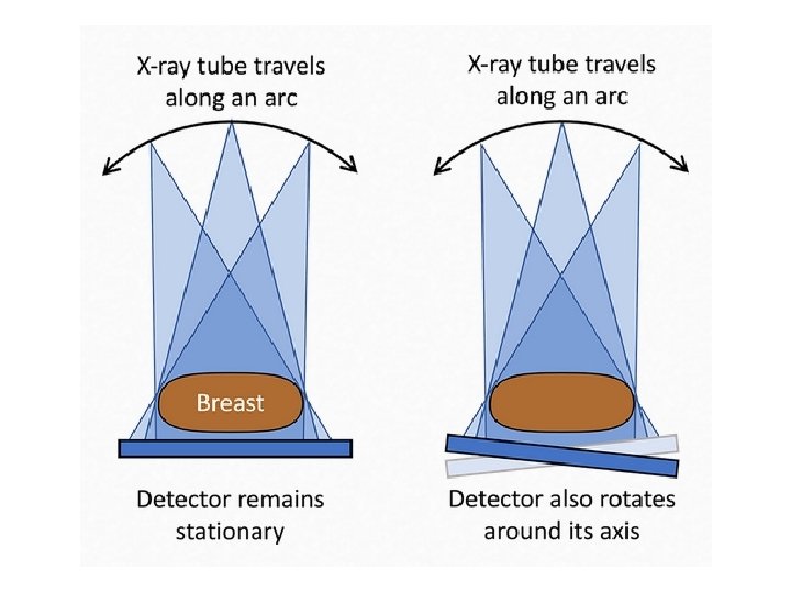
Tomosynthesis • Superimposed tissue can mask pathology and, often, the pathology in breast disease can be very subtle. Breast tomography uses digital radiography to reconstruct planar images of sections of the breast. There are two main methods of acquiring breast tomosynthesis: • The x-ray tube traverses along an arc acquiring images as it travels and the detector remains stationary • The x-ray tube traverses along an arc and the detector also rotates • The images are then reconstructed using filtered back projection or iterative reconstruction.
Advances in Mamography • Three recent advances in mammography include: o digital mammography, ocomputer-aided detection and o breast tomosynthesis
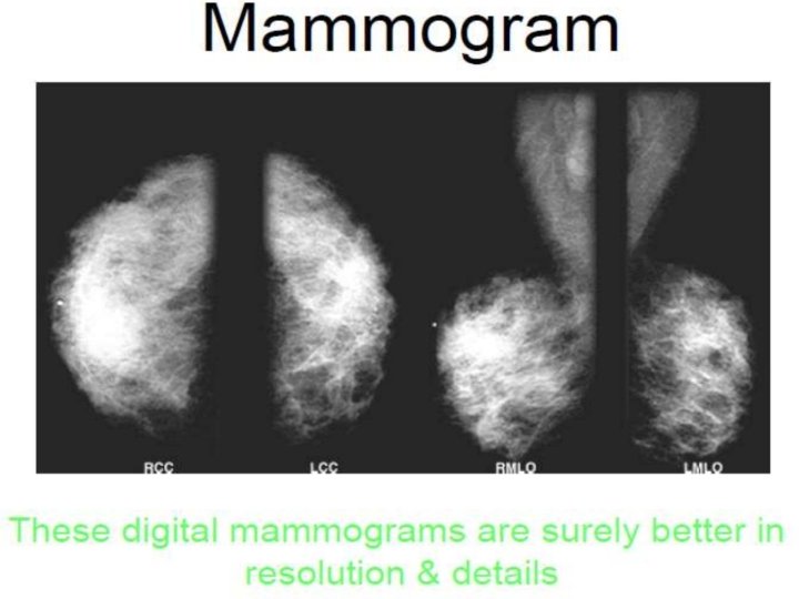
Digital mammography • also called full-field digital mammography (FFDM), • in which the x-ray film is replaced by electronics that convert x rays into mammographic pictures of the breast. • These detectors convert the x-rays that pass through them into electronic signals that are sent to a computer. • The computer then converts these electronic signals into images that can be displayed on a monitor and also stored for later use.
Breast tomosynthesis • • • ü ü • in which x-rays of the breast are taken at different angles to generate thin cross-sections while In 2 D mammograms, take images only from the front and side, this may create images with overlapping breast tissue. The 3 D representation of the breast is similar to the 3 d images created by standard CT technology. Tomosynthesis differs from CT technology in that significantly fewer x-ray beams are projected through the breast Breast tomosynthesis may also result in: earlier detection of small breast cancers that may be hidden on a conventional mammogram greater accuracy in pinpointing the size, shape and location of breast abnormalities fewer unnecessary biopsies or additional tests detecting multiple breast tumors clearer images of abnormalities
The movements of an x-ray mammography imaging system that produce digital mammographic tomosynthesis images.
Three axis reconstructed images showing improved contrast resolution when performing digital mammographic tomosynthesis. Same patient, A and C diagnostic images. B and D, Tomosynthesis images showing architectural distortion in the right upper outer quadrant suspicious for malignancy.
Pros and Cons • Pros 1. Provides enhanced lesion detection 2. Reduces false positive recalls 3. Allows more precise lesion localisation • Cons 1. Higher radiation dose (approximately double) 2. High contrast objects (e. g. surgical clips) can cause significant artefacts 3. Longer interpretation time 4. Requires substantially more data storage
Computer-aided detection (CAD) • • CAD techniques developed recently for breast cancer The im 3 D CAD digital tomosythesis system allows detection of both masses and microcalcification clusters at DBT examination(three-dimensional digital breast tomosynthesis). including detection of abnormal areas of density, mass, or calcification that may indicate the presence of cancer. The CAD system highlights these areas on the images. Therefore, (CAD) system is still in developing to help reduce reading time and prevent errors.
When Technologists taking selfie