Computer Graphics II Rendering CSE 168 Spr 21
![Computer Graphics II: Rendering CSE 168 [Spr 21], Lecture 3: Illumination and Reflection Ravi](https://slidetodoc.com/presentation_image_h2/7745fe14d89eab870d81f54902a53dcc/image-1.jpg "Computer Graphics II: Rendering CSE 168 [Spr 21], Lecture 3: Illumination and Reflection Ravi")
 due early next week § Next assignment")

![Diffuse Interreflection Diffuse interreflection, color bleeding [Cornell Box]](https://slidetodoc.com/presentation_image_h2/7745fe14d89eab870d81f54902a53dcc/image-4.jpg "Diffuse Interreflection Diffuse interreflection, color bleeding [Cornell Box]")


")
 properties of")


 –")

 N Irradiance Environment Map")
 properties of")
![Building up the BRDF • Bi-Directional Reflectance Distribution Function [Nicodemus 77] • Function based](https://slidetodoc.com/presentation_image_h2/7745fe14d89eab870d81f54902a53dcc/image-28.jpg "Building up the BRDF • Bi-Directional Reflectance Distribution Function [Nicodemus 77] • Function based")


 Emission BRDF Incident Light (from light source) Cosine")
 Emission BRDF Incident")
 Emission BRDF Incident Light")


 properties of")

")


- Slides: 48
Computer Graphics II: Rendering CSE 168 [Spr 21], Lecture 3: Illumination and Reflection Ravi Ramamoorthi http: //viscomp. ucsd. edu/classes/cse 168/sp 21
To Do § Homework 1 (ray tracer) due early next week § Next assignment direct lighting (on UCSD online). Will cover that material next week
Illumination Models Local Illumination § Light directly from light sources to surface § No shadows (cast shadows are a global effect) Global Illumination: multiple bounces (indirect light) § Hard and soft shadows § Reflections/refractions (already seen in ray tracing) § Diffuse and glossy interreflections (radiosity, caustics) Some images courtesy Henrik Wann Jensen
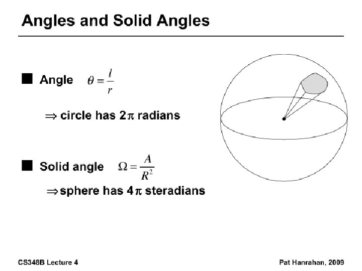
Diffuse Interreflection Diffuse interreflection, color bleeding [Cornell Box]
Radiosity
Caustics: Focusing through specular surface § Major research effort in 80 s, 90 s till today
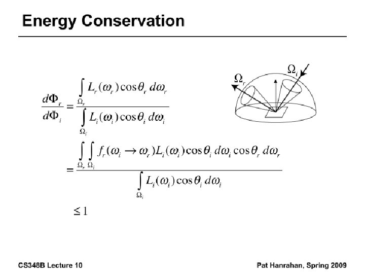
Motivation: BRDFs, Radiometry § Basics of Illumination, Reflection § Formal radiometric analysis (not ad-hoc) § Reflection Equation (Local Illumination) § Discussion of BRDFs § Rendering Equation (Global Illumination) on Thu § Formal analysis important for correct implementation
Radiometry § Physical measurement of electromagnetic energy § Measure spatial (and angular) properties of light § Radiance, Irradiance § Reflection functions: Bi-Directional Reflectance Distribution Function or BRDF § Reflection Equation § Simple BRDF models
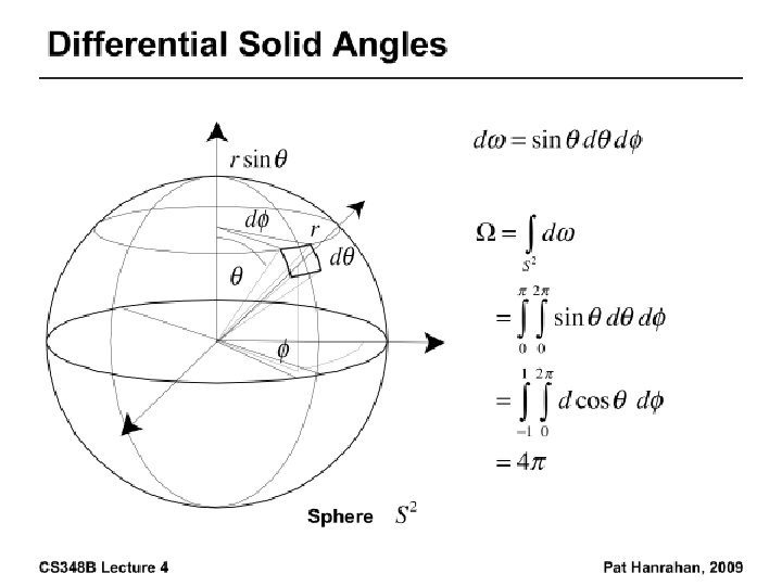
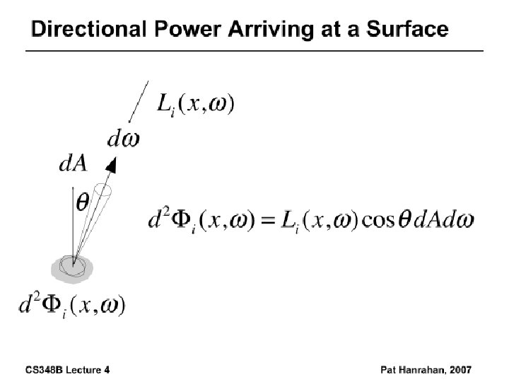
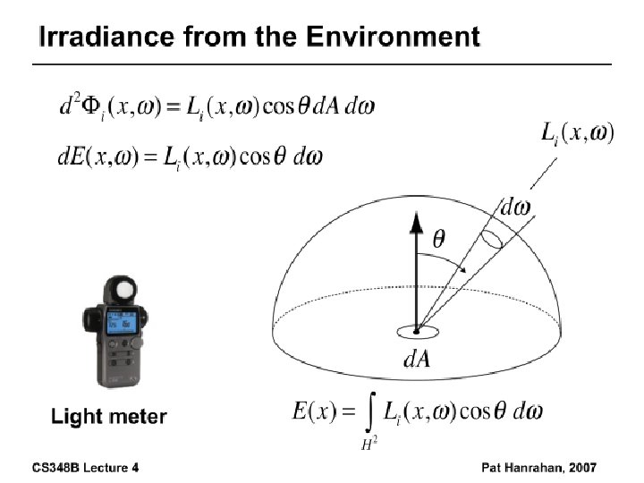
Radiance • Power per unit projected area perpendicular to the ray per unit solid angle in the direction of the ray • Symbol: L(x, ω) (W/m 2 sr) • Flux given by dΦ = L(x, ω) cos θ dω d. A
Radiance properties • Radiance constant as propagates along ray – Derived from conservation of flux – Fundamental in Light Transport.
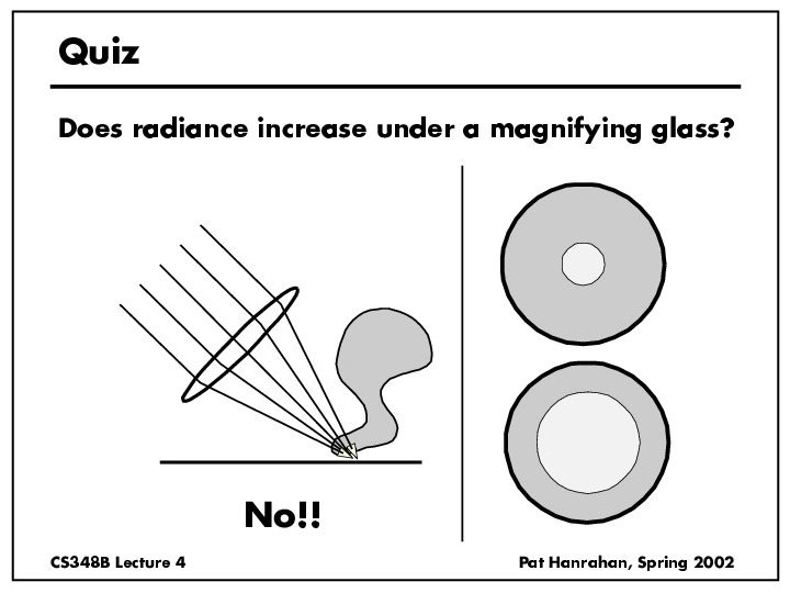
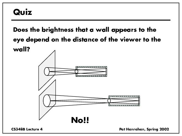
Radiance properties • Sensor response proportional to radiance (constant of proportionality is throughput) – Far away surface: See more, but subtends smaller angle – Wall equally bright across viewing distances Consequences – Radiance associated with rays in a ray tracer – Other radiometric quants derived from radiance – This course primarily about computing radiance
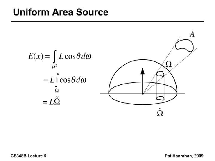
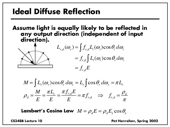
Irradiance, Radiosity • Irradiance E is radiant power per unit area • Integrate incoming radiance over hemisphere – Projected solid angle (cos θ dω) – Uniform illumination: Irradiance = π [CW 24, 25] – Units: W/m 2 • Radiant Exitance (radiosity) – Power per unit area leaving surface (like irradiance)
Irradiance Environment Maps R Incident Radiance (Illumination Environment Map) N Irradiance Environment Map
Radiometry § Physical measurement of electromagnetic energy § Measure spatial (and angular) properties of light § Radiance, Irradiance § Reflection functions: Bi-Directional Reflectance Distribution Function or BRDF § Reflection Equation § Simple BRDF models
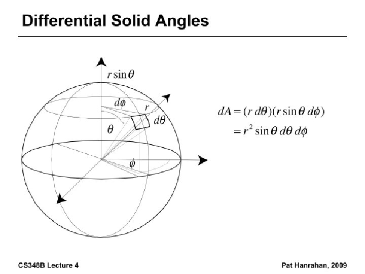
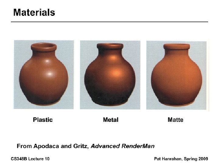
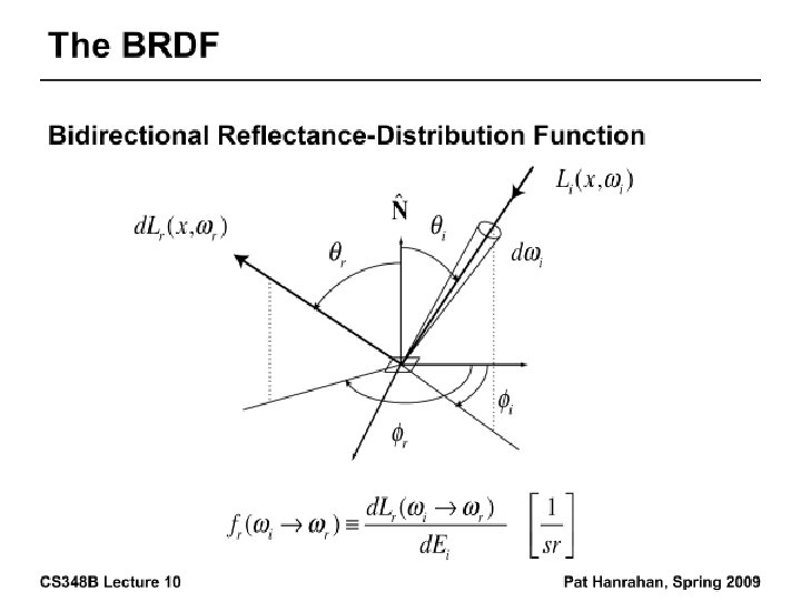
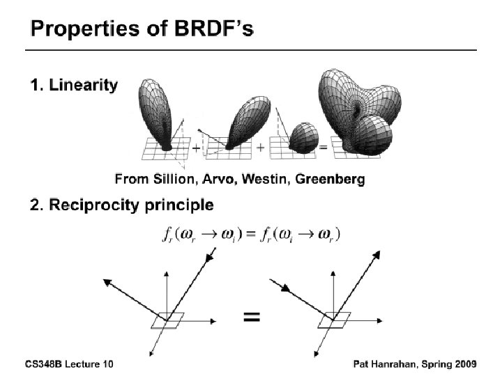
Building up the BRDF • Bi-Directional Reflectance Distribution Function [Nicodemus 77] • Function based on incident, view direction • Relates incoming light energy to outgoing • Unifying framework for many materials
BRDF • Reflected Radiance proportional Irradiance • Constant proportionality: BRDF • Ratio of outgoing light (radiance) to incoming light (irradiance) – Bidirectional Reflection Distribution Function – (4 Vars) units 1/sr
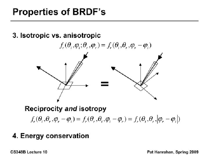
Isotropic vs Anisotropic § Isotropic: Most materials (you can rotate about normal without changing reflections) § Anisotropic: brushed metal etc. preferred tangential direction Isotropic Anisotropic
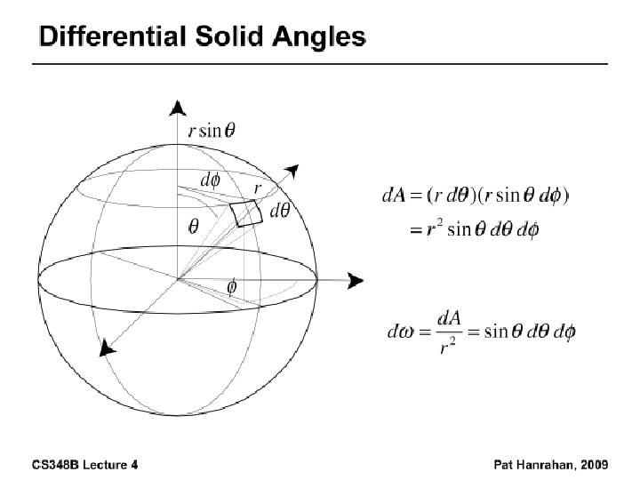
Reflection Equation Reflected Light (Output Image) Emission BRDF Incident Light (from light source) Cosine of Incident angle
Reflection Equation Sum over all light sources Reflected Light (Output Image) Emission BRDF Incident Light (from light source) Cosine of Incident angle
Reflection Equation Replace sum with integral Reflected Light (Output Image) Emission BRDF Incident Light (from light source) Cosine of Incident angle
Environment Maps § Light as a function of direction, from entire environment § Captured by photographing a chrome steel or mirror sphere § Accurate only for one point, but distant lighting same at other scene locations (typically use only one env. map) Blinn and Newell 1976, Miller and Hoffman, 1984 Later, Greene 86, Cabral et al. 87
Environment Maps § Environment maps widely used as lighting representation § Many modern methods deal with offline and real-time rendering with environment maps § Image-based complex lighting + complex BRDFs
Radiometry § Physical measurement of electromagnetic energy § Measure spatial (and angular) properties of light § Radiance, Irradiance § Reflection functions: Bi-Directional Reflectance Distribution Function or BRDF § Reflection Equation § Simple BRDF models
Brdf Viewer plots Diffuse Torrance-Sparrow Anisotropic bv written by Szymon Rusinkiewicz
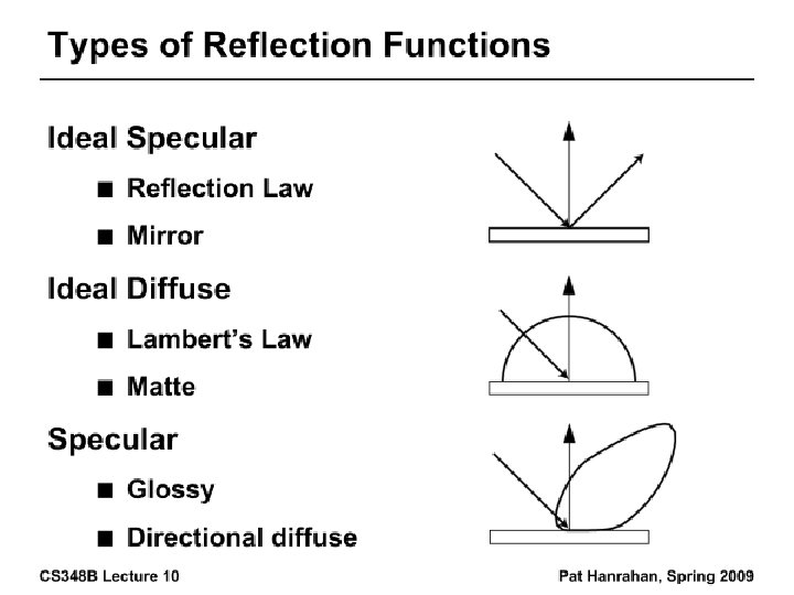
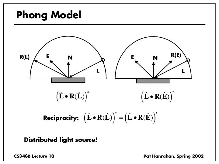
Specular Term (Phong)
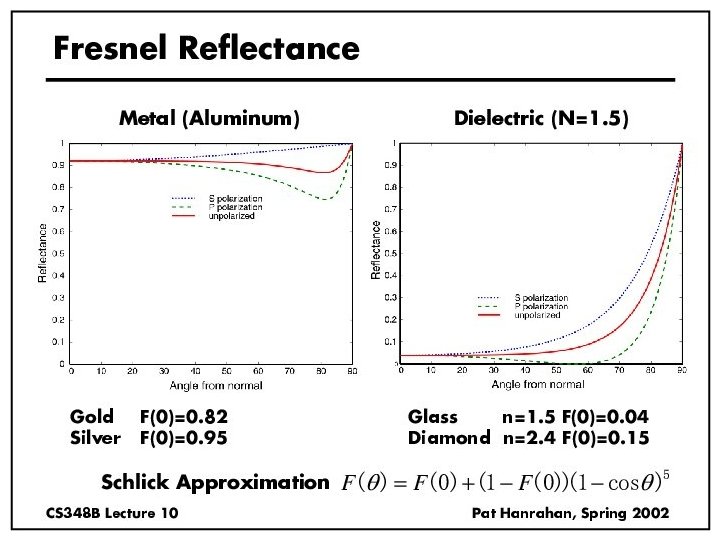
Torrance-Sparrow Fresnel term: allows for wavelength dependency How much of the macroscopic surface is visible to the light source Geometric Attenuation: reduces the output based on the amount of shadowing or masking that occurs. How much of the macroscopic surface is visible to the viewer Distribution: distribution function determines what percentage of microfacets are oriented to reflect in the viewer direction.
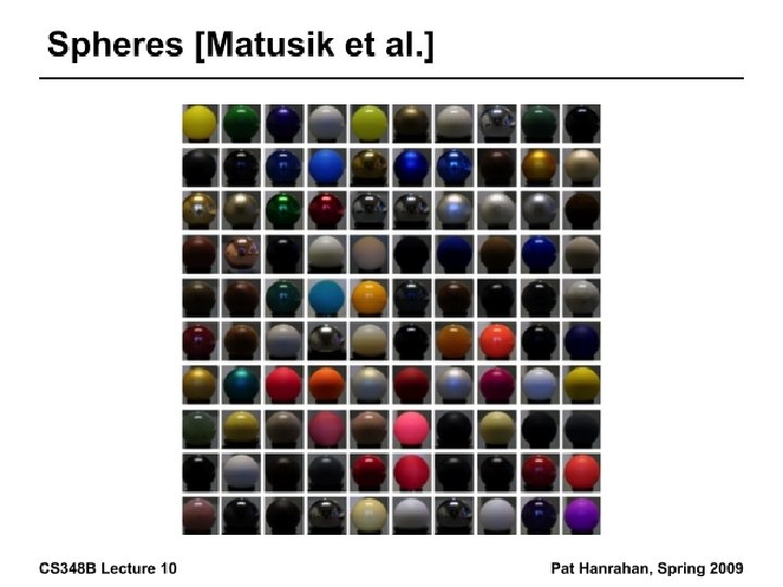
Other BRDF models § Empirical: Measure and build a 4 D table § Anisotropic models for hair, brushed steel § Cartoon shaders, funky BRDFs § Capturing spatial variation § Very active area of research