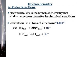
Chapter 20 Electrochemistry Electrochemical Reactions In electrochemical reactions


![Free Energy Under standard conditions, Standard conditions = 1 atm, 25°C, [1 M] concentrations Free Energy Under standard conditions, Standard conditions = 1 atm, 25°C, [1 M] concentrations](https://slidetodoc.com/presentation_image_h2/eb8769e9aa1f3a37cdf4b7acd5313035/image-29.jpg)


- Slides: 40

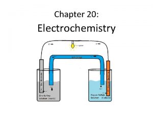
Chapter 20: Electrochemistry

Electrochemical Reactions In electrochemical reactions, electrons are transferred from one species to another. © 2009, Prentice-Hall, Inc.

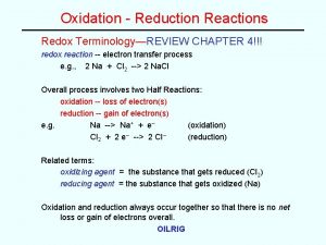
Oxidation Numbers In order to keep track of what loses electrons and what gains them, we assign oxidation numbers. © 2009, Prentice-Hall, Inc.

Oxidation and Reduction • A species is oxidized when it loses electrons. – Here, zinc loses two electrons to go from neutral zinc metal to the Zn 2+ ion. © 2009, Prentice-Hall, Inc.

Oxidation and Reduction • A species is reduced when it gains electrons. – Here, each of the H+ gains an electron, and they combine to form H 2. © 2009, Prentice-Hall, Inc.

Voltaic Cells In spontaneous oxidation-reduction (redox) reactions, electrons are transferred and energy is released. © 2009, Prentice-Hall, Inc.

Voltaic Cells • We can use that energy to do work if we make the electrons flow through an external device. • We call such a setup a voltaic cell. © 2009, Prentice-Hall, Inc.

Voltaic Cells • A typical cell looks like this. • The oxidation occurs at the anode. • The reduction occurs at the cathode. © 2009, Prentice-Hall, Inc.

Voltaic Cells Once even one electron flows from the anode to the cathode, the charges in each beaker would not be balanced and the flow of electrons would stop. © 2009, Prentice-Hall, Inc.

Voltaic Cells • Therefore, we use a salt bridge, usually a U -shaped tube that contains a salt solution, to keep the charges balanced. – Cations move toward the cathode. – Anions move toward the anode. © 2009, Prentice-Hall, Inc.

Voltaic Cells • In the cell, then, electrons leave the anode and flow through the wire to the cathode. • As the electrons leave the anode, the cations formed dissolve into the solution in the anode compartment. © 2009, Prentice-Hall, Inc.

Voltaic Cells • As the electrons reach the cathode, cations in the cathode are attracted to the now negative cathode. • The electrons are taken by the cation, and the neutral metal is deposited on the cathode. © 2009, Prentice-Hall, Inc.

Terminology for Voltaic Cells

Electromotive Force (emf) • Water only spontaneously flows one way in a waterfall. • Likewise, electrons only spontaneously flow one way in a redox reaction —from higher to lower potential energy. © 2009, Prentice-Hall, Inc.

Electromotive Force (emf) • The potential difference between the anode and cathode in a cell is called the electromotive force (emf). • It is also called the cell potential and is designated Ecell. • Cell potential is measured in volts (V). 1 V = 1 J/C © 2009, Prentice-Hall, Inc.

Standard Reduction Potentials Reduction potentials for many electrodes have been measured and tabulated. © 2009, Prentice-Hall, Inc.

Potential Ladder for Reduction Half. Reactions Stronger oxidizing agents Stronger reducing agents

Standard Cell Potentials The cell potential at standard conditions can be found through this equation: = Ered (cathode) − Ered (anode) Ecell (also written as: E reduction + Eoxidation) Because cell potential is based on the potential energy per unit of charge, it is an intensive property (amount is not a factor when calculating). © 2009, Prentice-Hall, Inc.

E cell & Spontaneity • Under standard conditions: – 25 C – 1 atm pressure – 1 M concentration • E cell> 0 = spontaneous • E cell < 0 = non spontaneous • E cell = 0 system as at equilibrium

Cell Potentials • For the oxidation in this cell, = − 0. 76 V Ered • For the reduction, = +0. 34 V Ered © 2009, Prentice-Hall, Inc.

Cell Potentials = Ered (cathode) − Ered (anode) Ecell = +0. 34 V − (− 0. 76 V) = +1. 10 V © 2009, Prentice-Hall, Inc.

Oxidizing and Reducing Agents • The strongest oxidizers have the most positive reduction potentials. • The strongest reducers have the most negative reduction potentials. © 2009, Prentice-Hall, Inc.

Oxidizing and Reducing Agents The greater the difference between the two, the greater the voltage of the cell. © 2009, Prentice-Hall, Inc.

Standard Hydrogen Electrode • Their values are referenced to a standard hydrogen electrode (SHE). • By definition, the reduction potential for hydrogen is 0 V: 2 H+ (aq, 1 M) + 2 e− H 2 (g, 1 atm) © 2009, Prentice-Hall, Inc.

Cell Notation • Shorthand notation for describing the voltaic cell: Anode information ll Cathode information Ex: Cu(s)l. Cu 2+ (aq 1. 0 M)ll Ag+ (aq, 1. 0 M)l. Ag(s) • Cell notation also applies when the metal(s) is not part of the reaction and an inert (non-reactive) electrode is used) Ex: Pt(s)l H 2(g) l. H+(aq) ll Ag+(aq)l Ag(s)

Example: Volatic cell with inert electrode

Voltaic Cells and Standard Reduction Potential 1. Sketch the diagram for the voltaic cell under standard conditions using the following half-cells. Cu(s) + Ag+(aq) Cu 2+(aq) + Ag(s) 2. Write a balanced equation for the overall reaction. 3. Give the standard line notation for each cell (cell notation). 4. Calculate the Eº values for the cells using standard reduction potentials and the following equation: Eºcell = Eºred Cathode - Eºred anode 5. Determine if the process is spontaneous (E >0)

Free Energy G (Gibb’s free energy) for a redox reaction can be found by using the equation: G = −n. FE where n is the number of moles of electrons transferred, and F is a constant, the Faraday. 1 F = 96, 485 C/mol e- -or- 1 F = 96, 485 J/V-mol e© 2009, Prentice-Hall, Inc.
![Free Energy Under standard conditions Standard conditions 1 atm 25C 1 M concentrations Free Energy Under standard conditions, Standard conditions = 1 atm, 25°C, [1 M] concentrations](https://slidetodoc.com/presentation_image_h2/eb8769e9aa1f3a37cdf4b7acd5313035/image-29.jpg)
Free Energy Under standard conditions, Standard conditions = 1 atm, 25°C, [1 M] concentrations G = −n. FE © 2009, Prentice-Hall, Inc.

Free Energy and electrochemistry Based on the following relationships: ΔG◦ = - n. FE◦, ΔG◦ = -RTln. K Calculate the ΔG◦ and K at 25◦C for the reaction previously described. Cu(s) + 2 Ag+ Cu 2+ + 2 Ag(s) Ecell = 0. 46 V

Nernst Equation • Remember that G = G + RT ln Q • This means −n. FE = −n. FE + RT ln Q © 2009, Prentice-Hall, Inc.

Nernst Equation Dividing both sides by −n. F, we get the Nernst equation: RT ln Q E = E − n. F or, using base-10 logarithms, 2. 303 RT log Q E = E − n. F © 2009, Prentice-Hall, Inc.

Nernst Equation At room temperature (298 K), 2. 303 RT = 0. 0592 V F Thus the equation becomes 0. 0592 log Q E = E − n © 2009, Prentice-Hall, Inc.

Nernst Equation: • Using the same system as in the previous problems, identify the voltage (E) when the concentration is altered [Cu 2+] = 0. 75 M [Ag+] = 0. 50 M

Concentration Cells • Notice that the Nernst equation implies that a cell could be created that has the same substance at both electrodes. would be 0, but Q would not. • For such a cell, Ecell • Therefore, as long as the concentrations are different, E will not be 0. © 2009, Prentice-Hall, Inc.

Nernst Equation: Concentration cell: Consider the concentration cell in which both chambers contain a silver electrode and a solution containing Ag+ ions. The left compartment contains [Ag+] at standard conditions of 1 M, 25 ◦ C and I atm. Calculate the cell potential at 25◦C when the concentration of Ag+ in the compartment on the right is the following: a. 1. 0 M b. 2. 0 M c. 0. 10 M

Commercial Voltaic Cells: • Requirements: – – Compact, robust Provide a constant voltage Concentrated to produce current over prolonged use. Rechargeable Primary batteries: cannot be recharged Secondary batteries: rechargeable (reaction in the battery can be reversed)

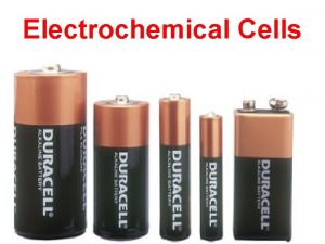
Common battery chemistries : • Zinc-carbon battery (primary): The zinc-carbon chemistry is common in many inexpensive AAA, C and D dry cell batteries. The anode is zinc, the cathode is manganese dioxide, and the electrolyte is ammonium chloride or zinc chloride. • Alkaline battery (primary): This chemistry is also common in AA, C and D dry cell batteries. The cathode is composed of a manganese dioxide mixture, while the anode is a zinc powder. It gets its name from the potassium hydroxide electrolyte, which is an alkaline substance. • Lithium-ion battery (rechargeable): Lithium chemistry is often used in highperformance devices, such as cell phones, digital cameras and even electric cars. A variety of substances are used in lithium batteries, but a common combination is a lithium cobalt oxide cathode and a carbon anode. • Lead-acid battery (rechargeable): This is the chemistry used in a typical car battery. The electrodes are usually made of lead dioxide and metallic lead, while the electrolyte is a sulfuric acid solution. http: //electronics. howstuffworks. com/everyday-tech/battery 3. htm

Batteries, cont. Dry cell battery (zinc/carbon) Lithium-ion battery

Fuel Cells: • Reactants supplied from an external reservoir. • Example: hydrogen-oxygen fuel cell Net reaction: 2 H 2 + O 2 2 H 2 O
 Ap chemistry chapter 18 electrochemistry test
 Introduction of electrochemistry
 Chapter 20 review electrochemistry
 Cell chapter 21
 Difference between galvanic cell and electrolytic cell
 Chapter 20 electrochemistry
 Section 2 reinforcement classifying chemical reactions
 What are redox reactions examples
 Section 2 classifying chemical reactions worksheet answers
 Types of reactions
 Unit 5 chemical reactions answers
 Cell chapter 20
 Electrochemical deposition
 Electrochemical theory of corrosion
 Electrochemical machining animation
 Refractory period anatomy
 Electrochemical series
 Types of electrochemical sensors
 Chloride half equation
 Electrochemical deposition
 Difference between dry and wet corrosion
 Electrochemical etch stop
 What are electrochemical series
 Electrochemical series order
 Electrochemical impulse
 Impedance definition
 The body's speedy electrochemical communication network
 Types of electrochemical corrosion
 Advantages of electrochemical machining
 The stage that creates an “electrochemical gradient”. *
 Breathalyzer chemical reaction
 Electrochemical gradient
 Lithium ion battery reaction equation
 Electrochemical gradient
 Giner electrochemical systems
 Electrons flow from anode to cathode
 Is electrochemistry
 Electrochemical impedance spectroscopy
 Electrochemical impulse
 Chapter 10 chemical reactions answer key
 Chapter 9 study guide chemical reactions

