The V Model Damian Gordon Contents 1 2


- Slides: 59
The V Model Damian Gordon
Contents 1. 2. 3. 4. 5. 6. 7. 8. Overview Details Advantages Disadvantages Interesting Reflection Review Summary
1. Overview
Overview • The “V Model” is a model that represents one method as to how software can be developed.
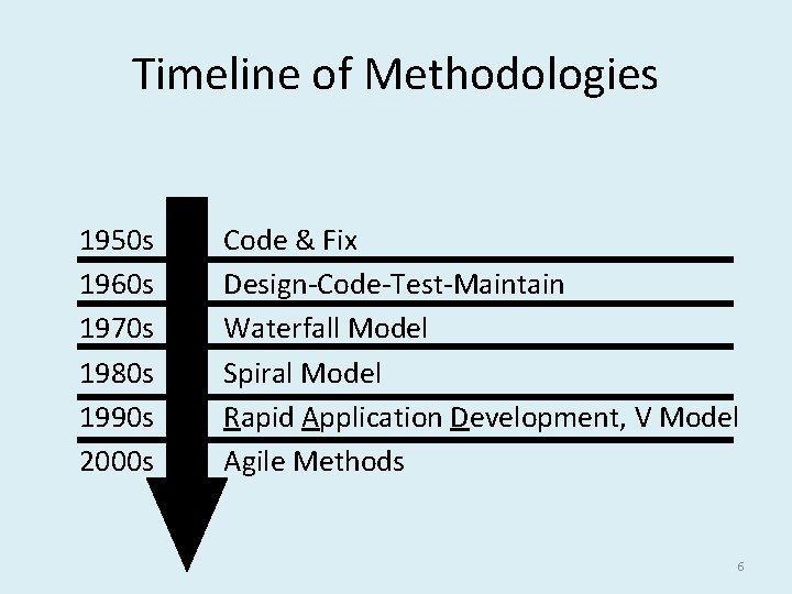
Timeline of Methodologies 1950 s Code & Fix 1960 s Design-Code-Test-Maintain 1970 s Waterfall Model 1980 s Spiral Model 1990 s Rapid Application Development, V Model 2000 s Agile Methods 6
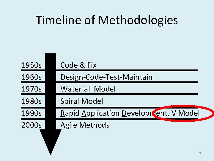
Timeline of Methodologies 1950 s Code & Fix 1960 s Design-Code-Test-Maintain 1970 s Waterfall Model 1980 s Spiral Model 1990 s Rapid Application Development, V Model 2000 s Agile Methods 7
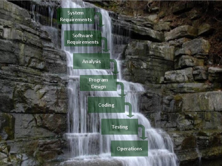
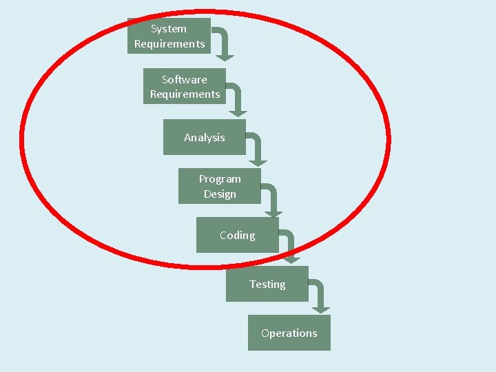
System Requirements Software Requirements Analysis Program Design Coding Testing Operations
System Requirements Software Requirements Analysis Program Design Coding Testing Operations
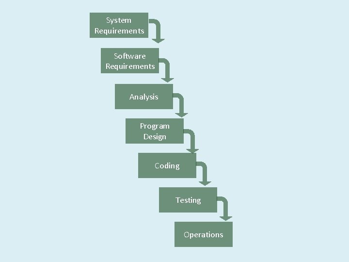
System Requirements Software Requirements Analysis Program Design Coding Testing Operations
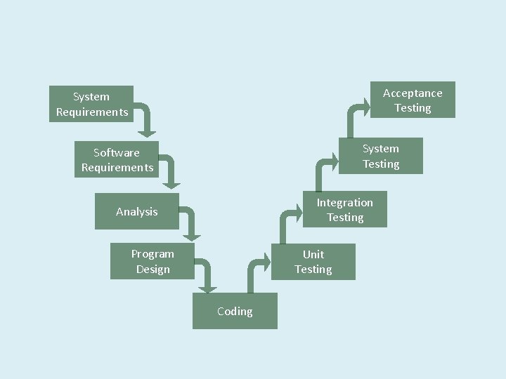
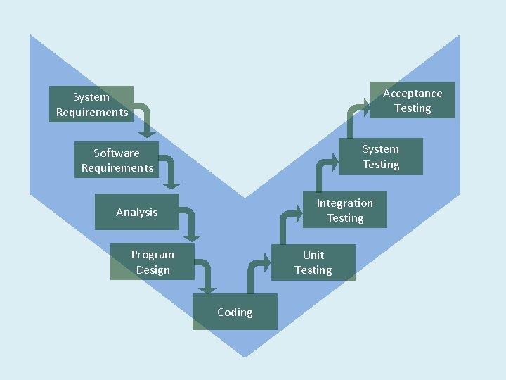
Acceptance Testing System Requirements System Testing Software Requirements Integration Testing Analysis Program Design Unit Testing Coding
Acceptance Testing System Requirements System Testing Software Requirements Integration Testing Analysis Program Design Unit Testing Coding
Reference • Forsberg, K. , Mooz, H. , 1991, "The Relationship of System Engineering to the Project Cycle", Chattanooga, Tennessee: Proceedings of the National Council for Systems Engineering (NCOSE) Conference, pp. 57– 65.
Kevin Forsberg • Born in 1934. • An American engineer, business consultant, and with Harold Mooz co-founder and executive director of The Center for Systems Management
Harold Mooz • Born in 1932. • An American engineer, business consultant, and with Kevin Forsberg co-founder and executive director of The Center for Systems Management
2. Details
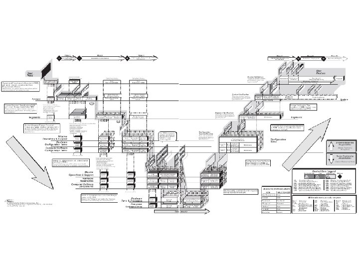
Abstract • “A new way of portraying the technical aspect of the project cycle clarifies the role and responsibility of system engineering to a project. This new three dimensional graphic illustrates the end-to-end involvement of system engineering in the project cycle, clarifies the relationship of system engineering and design engineering, and encourages the implementation of concurrent engineering. ”
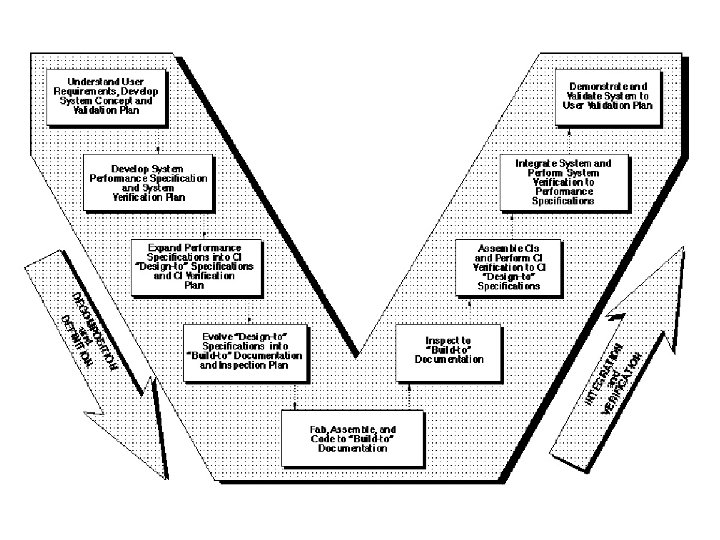
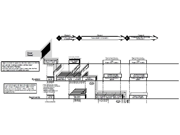
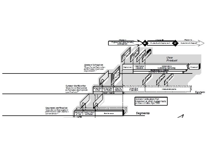
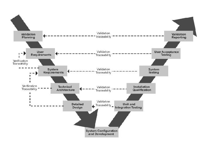
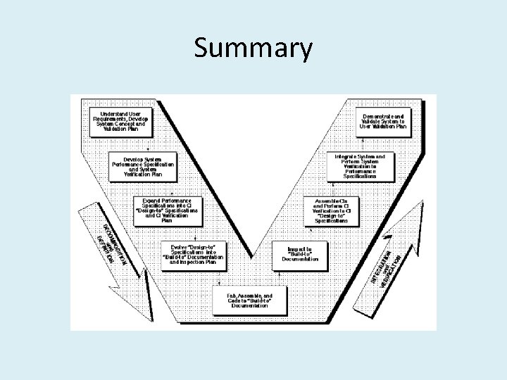
The “Vee” Model • Start with the user needs on the upper right, and ending with a user-validated system on the upper right.
Detailed Discussion of the “Vee” Model • As project development progresses, a series of six baselines are established to systematically manage cohesive system development:
Detailed Discussion of the “Vee” Model • 1. The first is the “User Requirements Baseline” established by the System Requirement Document approved and put under Configuration Management prior to the System Requirements Review.
Detailed Discussion of the “Vee” Model • 2. The second is the “Concept Baseline” established by the Concept Definition section of the Integrated Program Summary document at the System Requirements Review.
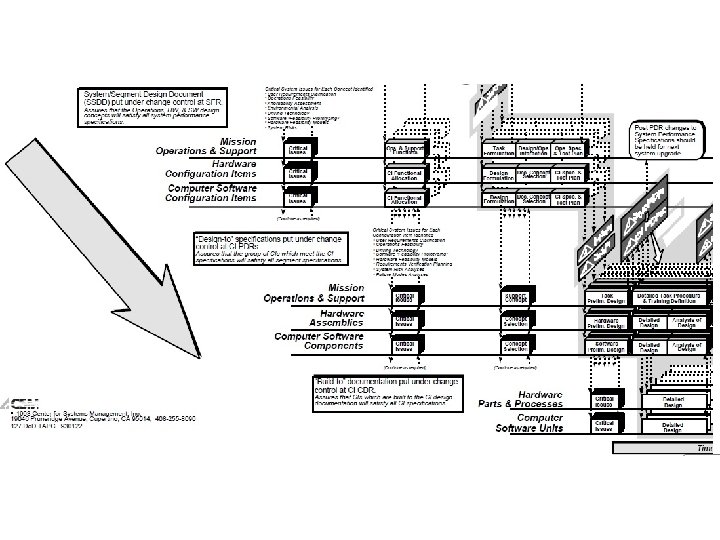
Detailed Discussion of the “Vee” Model • 3. The third is the “System Performance Baseline” (or Development Baseline) established by the System Performance Specification at the System Design Review.
Detailed Discussion of the “Vee” Model • 4. The fourth is the “‘Design-To’ Baseline” (or Allocated Baseline) established at the series of Preliminary Design Reviews.
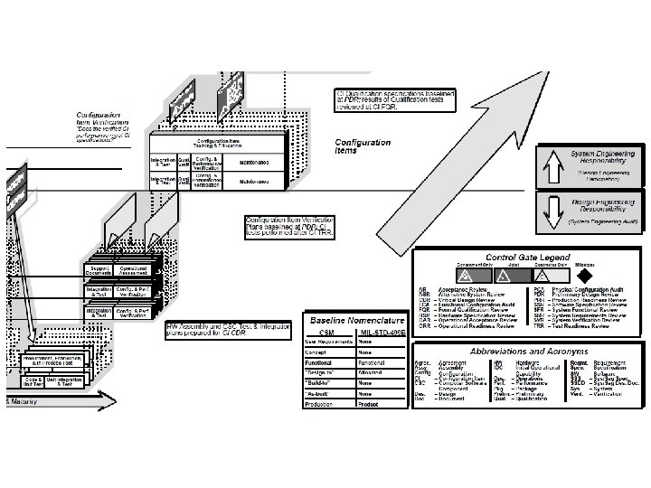
Detailed Discussion of the “Vee” Model • 5. The fifth is the “‘Build-To’ Baseline” (or preliminary Product Baseline) established at the series of Critical Design Reviews.
Detailed Discussion of the “Vee” Model • 6. The sixth is the “‘As-Built’ Baseline” (or Production Baseline) established at the series of Formal Qualification Reviews (FQRs). Each of the baselines is put under formal Configuration Management at the time they are approved.
Detailed Discussion of the “Vee” Model • Incremental Development • If the User Requirements are too vague to permit final definition at Preliminary Design Review, one approach is to develop the project in predetermined incremental releases. • The first release is focused on meeting a minimum set of User Requirements, with subsequent releases providing added functionality and performance. This is a common approach in software development.
Detailed Discussion of the “Vee” Model • Concurrent Engineering • If high iteration with User Requirements is required after the System Design Review (SDR), it is probable that the project has passed early Control Gates prematurely, and it is not sufficiently defined. • One cause of premature advance is that the appropriate technical experts were not involved at early stages, resulting in acceptance of requirements and design concepts which cannot be built, inspected, and/or maintained.
3. Advantages
Advantages • It is easy to understand use.
Advantages • Testing activities like planning, test designing happens well before coding. This saves a lot of time. Hence higher chance of success over the waterfall model.
Advantages • Proactive defect tracking – that is defects are found at early stage.
Advantages • Avoids the downward flow of the defects.
Advantages • It works well for smaller projects where requirements are very well understood.
4. Disadvantages
Disadvantages • Very rigid and least flexible.
Disadvantages • Software is developed during the implementation phase, so no early prototypes of the software produced.
Disadvantages • If any changes happen in midway, then the test documents along with requirement documents has to be updated.
Disadvantages • Not a good model for complex and objectoriented projects, or long and ongoing projects.
5. Interesting
Interesting When to use the V Model: • The V-shaped model should be used for small to medium sized projects where requirements are clearly defined and fixed. • The V-Shaped model should be chosen when ample technical resources are available with needed technical expertise.
Interesting • In common practice, the V model result in a project schedule with: – 20– 40% of the time invested for the first two phases, – 30– 40% of the time to coding, and – 20– 40% to testing and implementation.
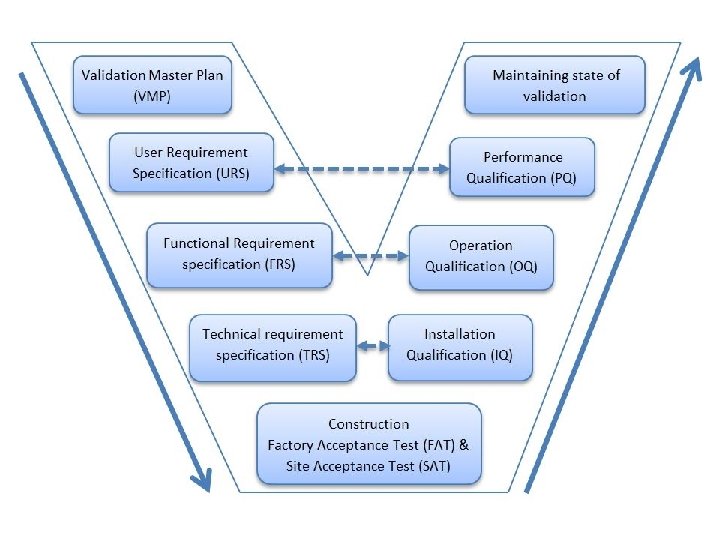
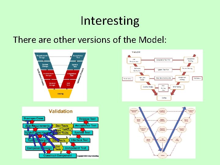
Interesting There are other versions of the Model:
6. Reflections
Reflections • The V Model works very well with Project Management approaches.
Reflections • The system defined at project start might not be suitable by the end of the project, since the customer will be dealing with change in their industry every business day.
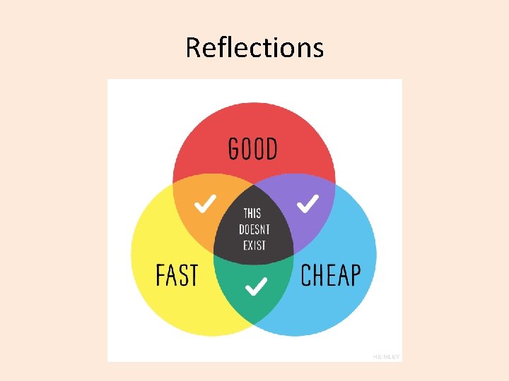
Reflections
7. Review
Review • What did we learn?
8. Summary
Summary