SST1 Data Acquisition Control H D Pujara Institute


 system. - Responsible for driving")


 VME based CPU")


 STOP DS_Set. Attr. Value (ds. Handle, \"Samp_Rate 1\", CAVT_FLOAT, &Samp. Rate")
; DS_EVENT_STATUSUPDATED: Client DS_EVENT_DATAUPDATED hr =")


- Slides: 86
SST-1 Data Acquisition & Control H D Pujara Institute for Plasma Research pujara@ipr. res. in
Institute for Plasma Research
Plan of the Talk Brief Introduction of SST-1 Objective of data acquisition and Control Timing System PXI & CAMAC based Data Acquisition system Major Constituents of Control systems Software aspects
Indian Tokamaks ADITYA SINP 0. 75 m 0. 25 m 1. 50 T 250 k. A 250 ms Circular Poloidal Limiters 0. 30 m 0. 075 m 2. 00 T 75 k. A 20 -30 ms Circular Poloidal Copper Water cooled Ohmic Transformer Copper Ohmic (Air Core) Vessel with Electrical break (Iron Core) Conducting Tokamak Major Radius R 0 Minor Radius a Toroidal Field BT Plasma Current Ip Pulse Duration Plasma Cross-section Configuration Limiters Coils Type (TF & PF) Current Drive & Heating transformer Vacuum vessel Shell Design & Fabrication M/S Toshiba, Japan Installation Indigenous 1989
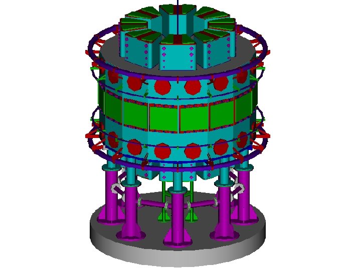
SST 1 MACHINE PARAMETERS MAJOR RADIUS MINOR RADIUS ELONGATION TRIANGULARITY TOROIDAL FIELD PLASMA CURRENT ASPECT RATIO SAFETY FACTOR AVERAGE DENSITY AVERAGE TEMP. : 1. 1 M : 0. 2 M : 1. 7 -2 : 0. 4 -0. 7 : 3 T : 220 k. A. : 5. 2 : 3 : 1 X 1013 cm-3 : 1. 5 ke. V PLASMA SPECIES : HYDROGEN PULSE LENGTH : 1000 s CONFIGURATION : : DOUBLE NULL : POLOIDAL DIVERTER HEATING & CURRENT DRIVE: LOWER HYBRID : 1. 0 MW NEUTRAL BEAM : 0. 8 MW ICRH : 1. 0 MW TOTAL INPUT POWER : 1. 0 MW FUELLING : GAS PUFFING ISOMETRIC CUT- VIEW OF SST-1
MACHINE PARAMETERS MAJOR RADIUS = 1. 1 m MINOR RADIUS = 0. 2 m ASPECT RATIO = 5. 5 ELONGATION = 1. 7 -2 TRIANGULARITY TOROIDAL FIELD = 0. 4 -0. 7 PLASMA CURRENT = 220 k. A PULSE LENGTH AVERAGE DENSITY : 1000 S = 1 X 1013 cm-3 AVERAGE TEMP. = 1. 5 ke. V PLASMA : HYDROGEN = 3 T
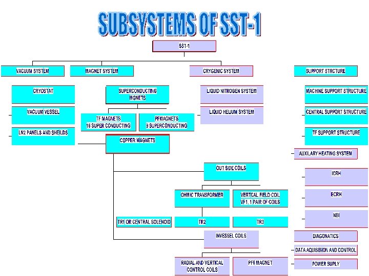
Vacuum Subsystem Vacuum Vassal made up of 16 Wedge shape sections 16 Interconnection ring • Cryostat • Pumping system • Gas Feed System
VACUUM VESSEL MODULE • VESSEL SECTOR • INTERCONNECTING RING : 1 • TOP VERTICAL PORT • BOTTOM VERTICAL PORT : 1 • RADIAL PORT FLANGE : 1 • RADIAL PORT BLANKING FLANGE TOP PORT : 1 VESSEL RING : 1 VESSEL SECTOR RADIAL PORT : 1 PORT FLANGE BLANKING FLANGE BOTTOM PORT
SST 1 CRYOSTAT Cryostat Parameters: Vertical Height : 2. 6 m Outer Diameter : 4. 4 m Inner Diameter : 0. 355 m Wall Thickness : 10 mm Total Surface Area : 59 m 2 Total Volume : 39 m 3 Total Weight : 4520 kg Material : SS 304 L
SST-1 MAGNET SYSTEM Requirements: • Confinement, Shaping and Equilibrium Fields • Ohmic Flux Storage • Feed-Back Control Supercondcting Magnets: • Toroidal Field (TF) Coils : Nos. • Poloidal Field (PF) Coils : Copper Nos. Magnets (Water Cooled) : • Ohmic Transformer (TR) Coils : Nos. 16 9 7 • Poloidal Field (PF ) Coils ( in-Vessel): 2 Nos. • Position Control Coils ( in-Vessel) Nos. : 2
SST-1 Poloidal Field Coils Design Drivers: • Support single & double null equilibria with wide range of Triangularity ( 0. 40. 7), Elongations ( 1. 7 -1. 9), li (0. 75 -1. 4), p ( 0. 01 -0. 85) & slot divertor configuration • Limiter operation during Plasma current ramp up Parameters of PF Coils
Gas feed System • Plasma of Hydrogen gas • Gas fueling during normal operation of 1000 sec. • Uniform gas distribution. • 28 pizo electric gate valve around the machine. • Plasma Density control for constant density • Online feed control by adjusting gas flow.
Auxiliary Heating system • Lower hybrid current drive (LHCD) system. - Responsible for driving the plasma and maintain current for 1000 sec. -One Megawatts of CW power at 3. 7 Ghz -Two High Power Klystron, each delivering 500 KW - Ohmically driven Ip (110 KA to 220 Kam) will be Taken over by LHCD - Circular plasma will be shaped with PF coils - Will be lunched through redial port to a grill of 64 wave guides - Pressured transmission line to avoid the Breakdown
Ion Cyclotron Resonance Freq. • • Tetrode based 1. 5 MW ICRF system. Frequency of operation 20 to 92 MHz Temp of 1. 0 Ke. V Lunched through radial port, four antennas 375 Kw each • Pressurized 90 meter long & 9 inch dia 50 ohm transmission line • Online stub and frequency matching for optimum power transfer. • Reflected power will be compensated with hike in input RF power.
Electron Cyclotron Resonance Freq. Heating. • Gyrotron Based 200 KW CW @ 84 GHz • Focused Microwave beam of 18 mm radius.
SST 1 ECRH SYSTEM Objectives: • Pre-Ionisation & Plasma start up • Electron Cyclotron Heating to assist Current drive during LHCD Main Parameters • Gyratron Frequency : 82. 6 GHz • Output Power CW : 200 k. W • Output Mode : HE-11 • Operating TF Field : • Fundamental : 3 T • 2 nd Harmonic : 1. 5 T • Exit dimensions of Waveguide : 63. 5 mm
SST-1 LHCD SYSTEM Frequency : 3. 7 GHz. Power ( 2 klystrons each of 500 k. W CW): 1 MW Antenna type : Grill # of subwaveguides : 32 x 2 rows Periodicity (with 2 mm thick septa) : 9 mm Subwaveguide opening : 76 x 7 mm 2 Design NII (at 90 o phasing) : 2. 25 NII variation (from 40 o to 60 o phasing) : 1. 0 4. 0 Klystron input power : 10 Watt
Plasma Facing Components of SST-1 Design Drivers: • Steady state heat and particle removal • 1 MW power Input • Surface temperature 1000 0 C • Baking up to 350 0 C • Electromagnetic forcesss during VDE, disruptions and halo currents • Modularity • Isostatically pressed, low ash content, Graphite • Tiles mechanically attached to High strength copper alloy (Cu. Zr & Cu Cr. Zr) backplate; • Cooling tubes (SS 304) embedded in & brazed to the back plates.
PLASMA FACING COMPONENTS OF SST-1
Objective and Requirements of DAS SST-1 is a steady state device… The system must capable enough to acquire all required physics information. . Due to continuous nature of operation … no physics information should be lost. . And no unnecessary data should be acquired. Concept of event for data reduction, Scheduled and un scheduled events. If required … must offer lossless acquisition. . Provide support for real time visualization of data. On line processing for Physics Information. Remote operation, processing and viewing… GUI based local and synchronous operations. Tagged with events for post processing and viewing. Distributed DAS for batterperformance data managements enhancement with growing tech
How SST-1 DAS Differs Most of the Tokamak operates in pulse mode Discharge duration could be few seconds Captures data during discharge. Retrieves it later on for analysis Display of data as a single trace. Do not demand any need of viewing data during discharge since discharge is limited for few seconds Generates manageable data during shot-10 Mb or so
However SST 1 will be operated under steady State for 1000 Seconds Demands online viewing 1000 seconds 20 minutes, can’t wait till end of the pulse Online processing to infer physics parameter like Density, Plasma current Demands large local buffers for storage Generates large amount of data Demands transfer to host-as fast as possible for loss less acquisition Storage for post processing Tagging of events and time These all puts significant effect on acquisition instruments
Above requirements poses many Technical problems Large amount of data Network load increases substantially Storage requirements grows enormously Processing needs also grows and demands faster CPUs Large buffers or Multi buffer schemes Deterministic nature of network and minimum latency Here the root cause is LARGE AMOUNT OF DATA
How one can reduce the data? – EVENT DRIVEN SAMPLING Acquire data at lower sampling rate during low activity period Change Sampling rate as and when important event occurs Revert-back to normal sampling rate after / t If everything is sequential and pre determined ---window based acquisition Event driven sampling
How much reduction in data one can achieve in Event base triggering? · Depends on number of events, duration of events. · Sampling rate during event. · Base level Sampling rate. · Depends on diagnostic and its needs.
What are the problems caused by event driven sampling Scheme? Each diagnostic has to identify the events, its duration and required Sampling rate. · Each sub-system like NBI, LHCD, ICRH etc. Has to identify events. · Generation of events- Electronics hardware. Encoding of events- numbering of events. · Distribution of events to various sub-systems and digitizers, Its Time criticality. · · Selection of digitizer which can accepts such events triggering. · Time tagging of events while storing the data. · Event recording- Sampling rate, event etcs needs to be stored for post archival. This basically demands a very unique timing/triggering system.
Employ various diagnostics to study the various parameters like Electron Density Bolo meters Soft X-Ray radiation Charge-exchange Langmiur Probes Thomson scattering Plasma Current Microwave Interferometer Loop Voltage Spectroscopy Electron Temperature
S. N DIAGNOSTICS 1 Mirnov coils 2 No. of channels Sampling Freq Type of Acquisition 44 1 Mhz Event based Diagnostics and Events 100 ms Multiple window # Current Ramp up Two component Magnetic probes 48 Halo Rogowski coils 50 10 KHz Remarks 100 ms Multiple window # Current Ramp up # LHCD / NBI ON # Gas puff/ Pellet # Current ramp down or Disruption Continuous Control + Daq 1 Mhz Event Based 100 ms multiple windows # Z-position(thres) # Disruption 16 1 k. Hz Continuous control + DAQ 4 10 KHz Continuous control + DAQ # LHCD / NBI ON 3 # Gas puff 4 Saddle loops 5 Rogowski coils 6 Fiber optics Current sensor 2 7 Voltage Loops 24 8 Diamagnetic Loops 4 10 KHz Continuous Monitor + DAQ 9 Hall sensors 24 10 KHz Continuous Control + DAQ 10 Bolometer System 10 20 100 Hz 20 KHz Continuous # Current ramp down # Disruption 10 KHz
11 SXR Imaging System 10 125 100 Hz 1 Mhz Continuous Event Based 12 HXR Tomography 10 100 Hz 1 MHz Continuous Event Based Sodium Iodide (NI) 2 5 100 Hz 1 MHz Continuous Event Based 2 5 10 KHz 1 MHz Continuous Event Based 13 14 VUV Broadband 15 FIR interferometer 24 10 KHz Continuous 16 Spectroscopy 12 8 10 KHz 1 MHz Continuous Event Based 17 ECE Radiometer 16 8 1 KHz 1 Mhz Continuous Event Based 18 Langmuir Probes 32 64 10 KHz 1 MHz Continuous Event Based 19 Michelson @ Interferometry Charge Exchange 20 8 Monitor + DAQ 100 ms multiple windows # NBI ON (L-H trans & H mode) # Gas puff/pellet # Disruption 100 ms multiple windows # NBI ON (L-H trans & H mode) # Gas puff/pellet #Digital Disruption Counts 100 ms multiple windows # NBI ON (L-H trans & H mode) # Gas puff/pellet # MARFE / DP # Disruption
Diagnostics and Data Volume
Total of 250 Data channels demanding Continuous Acquisition for all 1000 sec. @ 10 Khz sampling Generate 3. 5 Gbytes of data. Generate 3. 5 Mbytes/sec Total of 450 Channels at fast sampling rate @1 Mhz, event based… Number of schedule and unscheduled events about 5 Total Data 225 Mbyte on board timing/triggering system
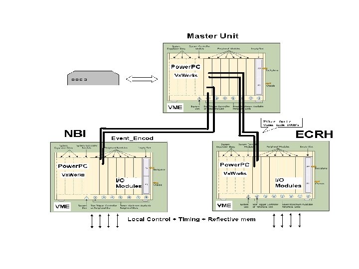
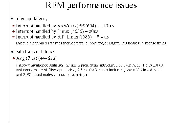
Timing System SST-1 is consists of various subsystems Subsystems are Physically wide apart. Time synchronization between the subsystem is required for proper and reliable operation of Experiment. Exchange of events between sub systems is essential for smooth operation. Deterministic distribution within 5 micro sec Common clock reference for tight simultaneity between subsystem and central control. Event based sampling to limit data volume and not to lose the physics information.
Constituents of Timing system Master Control Unite (Event Sequencer & distributor) VME based CPU Fiber Optic communication Link @100 Mbits/sec Tree Structure Event Encoder Module 8 Event Inputs 16 bit code Fiber optic link with master unit Timer Module Event Decoder Programmable Delay & Trigger generators. Reference Clock Fiber optic link with master unit
Available BUS Options ISA 8 bit, 16 bit, Max 8 MB/s Limitation of slots PCI 32 Bit, 132 Mbyte/sec CPCI 32 Bit 64 Bit 132/256 MB/s PXI Extension of PCI, Sync. Clock, Trigger lines, Local Bus EMI/EMC, Cooling, Pug & Play, VISA VME 32/64 Bit, 40/80 MB VXI 32 Bit, 40 MB/s 10 MHz sync clock, Trigger lines, Local Bus, Module ID, Resource manager, EMI/EMC IEEE 1934 Serial Bus, 200/400 Mbits CAMAC
Available BUS Options For Instrumentations ISA 8 bit, 16 bit, Max 8 MB/s Limitation of slots PCI 32 Bit, 132 Mbyte CPCI 32 Bit 64 Bit 132/256 MB/s PXI Extension of PCI, sync. Clock, Trigger lines, Local Bus EMI/EMC, cooling , P & P VISA VME 32/64 Bit, 40/80 MB VXI 32 Bit, 40 MB/s 10 MHz sync clock, Trigger lines, Local Bus, Model ID, P & P, Resource manager EMI/EMC , VISA IEEE 1934 Serial Bus, 200 M/400 Mbits CAMAC
What is the solution Considering the data rate generation as per the requirements For Slow Diagnostics Demanding Continuous Loss less acquisition. Volume of data generation is less per sec FIFO/Dual Ported RAM buffer Fast back plane Data streaming to disk For Fast Diagnostics demanding higher sampling rate Data must be stored on Onboard Memory Multi Buffer or Segmented memory for different events
Opted for Fast Diagnostics: CAMAC based stand alone system has been chosen. For this a ISA bus based 16 Bit Crate Controller and a special digitizer supporting multiple segments of memory for Events has be developed in house. PXI for Slow Diagnostics: The PXI based system has been chosen. The major reason of choosing PXI is that it is based on the industry standard PCI bus. For making it perfect for instrumentations, the additional trigger lines, local bus and a clock signal has been incorporate. In addition the chassis complies with EMC/EMI standard. All the PXI module comes bundled with Plug and Play driver for windows platform. The bus offers a transfer rate of 132 Mbytes @33 MHz & Fiber optic link to host.
Opted for CAMAC based- Computer Automated Measurement And Control. Fast Diagnostics PXI for Slow Diagnostics Data Streaming to the disk VME For control applications
PCI bus • PCI bus developed by Intel. • Introduced in 1993. 486 motherboards use PCI as well. • Clearly is the Bus of the ‘future’
PCI Highlights • 32 -bit bus that normally runs at a maximum of 33 MHz • Greater system performance , with a maximum data transfer rate of 132 MB/s • Offers excellent expandability for highperformance peripheral devices • investment spanning multiple CPU generations • Processor independent
Computer Bus Architecture RAM 32 -bit PCI bus Hard drive CPU local bus (32 -bit) PCI Bridge 32 -bit Video ISA bridge 16 -bit ISA Slot PCI Slot
PCI bus 33 MHz, 32 -bit, address lines and data lines are shared – Memory (where cards live) – IO (chip connection) – Configuration • Bios on bootup 16 15 31 0 Device ID Vendor ID Status Command Class Code BIST Header Latency Rev Cache Base Address Registers • Each slot on the PCI bus has the configuration registers shown at the right. Cardbus CIS Pointer Subsystem ID Sub. Vendor ID Expansion ROM Base Address Reserved Max. Lat Min. Gnt Int Pin Int Line 0 x 00 0 x 04 0 x 08 0 x 0 C 0 x 10 0 x 14 0 x 18 0 x 1 C 0 x 20 0 x 24 0 x 28 0 x 2 C 0 x 30 0 x 34 0 x 38 0 x 3 C
The PCI bus • Wide Industry Support • Plug and Play capability • Thousands of software products • 32 -bit data transfers at 33 MHz (132 Mbytes/sec) • PCI is a de facto standard • Automatic Resource Allocation BIOS will normally "lock" the "PCI IRQ and DMA Settings" • PCI IRQ and DMA Settings can also be set manually But limited slots…. 1 2 3 4
Peripheral Sizes in PCI and Compact. PCI PXI/Compact. PCI Half Size Full Size 6 U PCI boards can be redesigned to fit in PXI/Compact. PCI with little or no electrical changes. 3 U • Eurocard Packaging Proven over decades of use in industrial applications (VME, VXI, etc. ) Defined by IEEE 1101 Standard
PC Motherboard = Controller + Backplane PC Motherboard with 4 PCI slots 1 2 3 4 Compact. PCI 8 -slot Backplane Compact. PCI Embedded Controller 1 2 3 4 5 6 7 8
Electrical Extensions : Star Trigger Peripheral Local Bus Peripheral Star Trigger Controller System Controller 10 MHz CLK 132 Mb/s, 33 MHz, 32 -bit Computer Bus Trigger Bus • Integrated 8 Trigger Lines, 10 MHz reference clock, Star Trigger Bus • Local Bus between adjacent slots 13 lines
Mechanical Extensions Mandatory Active Cooling • System-level environmental specifications for EMC, shock, vibration, and humidity • Defined embedded controller location
PXI/Compact. PCI Form Factors 3 U PXI/CPCI J 2 64 -bit PCI and PXI Features J 1 32 -bit PCI J 5 J 4 6 U PXI/CPCI PXI Reserved J 3 PXI Reserved J 2 64 -bit PCI and PXI Features 6 U Adapter Panel J 1 32 -bit PCI
Software Extensions PXI speeds application development because: • PXI Controllers MUST support a standard software framework by including a pre-loaded OS: – Windows NT – Windows 9 x • Peripherals modules MUST be supplied with a WIN 32 Device Driver
PXI and PC Software is Identical • Operating systems and application software run unchanged on PXI systems • Configuration tools recognize PXI modules as PCI devices
PXI Also Works with Other Standards PXI Chassis VXI or VME Chassis GPIB INSTRUMENT GPIB MXI Compact. PCI
Controller Option • Embedded controllers – Most compact solution – Modular – Pentium and Pentium III Class • Remote MXI-3 controllers –Short or long 200 meter distance –cupper or fiber connectivity 1. 2 Gbits/s can sustain data transfers at over 80 Mbytes/s –Fully transparent –Low cost
MXI-3 Benefits • • • More slots for PCs and PXI/Compact. PCI Very high performance serial fiber link 1. 2 GB/s Easy to integrate — software transparent 200 meter L O N G distances Low cost
Front_end Electronics with built in Intelligence for Plasma Diagnostics. During operation no entry to hall Remote setting of front end electronics is required Signal Originating from diagnostics has large dynamic ranges Dynamic control of various settings of Front_end Electronics Gain, BW Shielded twisted pair Cables Opto Isolations CANBuse base system, multi drop, serial bus @1 MBits/s, msg exchange with priority, priority and address is part of msg, received by all, act if req.
PXI Based Lossless Continuous Data Acquit ion Platform Windows 2000 Development Tool Lab. Windows/CVI Data Socket based Client/Server Architecture Direct Data Streaming to Hard Disk 1. 2 GB/s Fiber Optic Link
d. Samp. Rate = 1200000; i. Half. Bufs. To. Read = iteration ; Get. Ctrl. Val (panel. Handle, PANEL_LST 1, &Samp. Rate 1); Server Architecture ul. Count 1 = Samp. Rate 1*Num_of_Channel*2; pi. Buffer 1 = (short *)malloc(ul. Count 1*2) ; pi. Half. Buffer 1 = (short *)malloc(ul. Count 1); DS_Control. Local. Server (DSConst_Server. Launch); Init_DA_Brds (1, &brd 1); Init board AI_Configure (1, -1, 2, 10, 0, 1) DS_Open ("dstp: //202. 41. 112. 140/dataport 1", DSConst_Write, DSCallback, NULL, &ds. Handle); DAQ_DB_Config(i. Device 1, i. DBmode. ON) SCAN_Start(i. Device 1, pi. Buffer 1, ul. Count 1, i. Samp. TB 1, u. Samp. Int 1, i. Scan. TB 1, u. Scan. Int 1);
Wihle (loops <100) STOP DS_Set. Attr. Value (ds. Handle, "Samp_Rate 1", CAVT_FLOAT, &Samp. Rate 1, 0, 0); DAQ_DB_Half. Ready(i. Device 1, &i. Half. Ready 1, &i. DAQstopped); if ((i. Half. Ready 1 == 1) DAQ_DB_Transfer(i. Device 1, pi. Half. Buffer 1 fwrite (pi. Half. Buffer 1, 2, ul. Pts. Tfr, ffp 1); Plot. Y (panel. Handle, PANEL_GRAPH DS_Set. Data. Value (ds. Handle, CAVT_SHORT|CAVT_ARRAY DS_Update(ds. Handle);
DS_Open (URL, DSConst_Read. Auto. Update, DSCallback, NULL, &ds. Handle); DS_EVENT_STATUSUPDATED: Client DS_EVENT_DATAUPDATED hr = DS_Get. Attr. Type (ds. Handle, "Samp_Rate 1", &type)) If (data type matches) DS_Get. Attr. Value (ds. Handle, "Samp_Rate 1", type, &Samp. Rate 1)
DS_Get. Data. Type If (data type matches DS_Get. Data. Value (ds. Handle, type, data. Array Integrate(input_integrater Plot. Y (main. Panel, MAINPNL_GRAPH)
Observed Performance of PXI on Windows 2000 Data Acquisition Module with 16 Channels, 12 Bit ADC, supporting aximum 1. 2 Msamaples/sec. 2 channel DAC, 2 Channel of counter/timers and 8 Lines of gital I/O. Such three modules. ( 48 Ch of Analog In, 6 ch of Analog out, 24 I/O nd 6 counter timers) Continuous Data Acquisition. . Acquisition Server (48 channel @ 10 k. Hz, writing to file for 1000 sec. and pushing the all 48 channel on network using Data Sockets ) Synchronized Continuous Acq. with start trigger (One common start trigger to module and the same is applied to rest by the back plain) one Single Shot application. . On fly sampling rate changing in case of Scheduled Event triggering. Multi. Trigger: In case of event based sampling 100 events with time gap of 70 msec can be acquired with ploting of the data and with out plot the subsequent time gap can be 15 msec. (This was tried with pre/post trigger facility
Following performance was very recently HP Vectra P-III @1. 2 GHz supports 96 channels acquisition @10 KHz with pushing all data no network and storing it on hard disk with few channels plotting on local machine. Embedded PC of NI P-II @1. 2 GHz working supports up 96 channel @20 KHz. This is double the channel handling capacity compare with PCL machine working at P-III @500 MHz
CAMAC based Data Acquisition for fast diagmnostics Platform Windows 2000 Development Tool. Lab. Windows/CVI Data Socket based Client/Server Architecture On board memory, Multiple segments Standalone CAMAC system
Crate Controller 16 bit parallel crate controller Data transfers under PIO and DMA mode Device Driver with DAM for Windows 2000 platform Differential line drivers to support the longer distance ISA bus
CAMAC Digitizer for Fast Diagnostics Design our own CAMAC Module Independent 8 bit ADC per channel, +/- 5 V Four channel per module 512 KB memory per channel Single width CAMAC module Digitizing rate up to 1 MHz Selectable pre/post trigger samples Selectable segment size Facility for Onfly Reading Supports Continuous, Transient and Monitoring Mode
INPUT SIGNAL ON FLY READ BUFFER HF CLOCK GENERATOR FF CAMAC READ LINES EF L A T C H A D C INSTRUMENTATION AMPLIFIER CLOCK DIVISION CLK FIFO CONTINUOUS READ BUFFER EN TRANSIENT READ BUFFER W* CLOCK Function R Decoder CLOCK SELECTION HF START TRIGGER SAMPLING CLOCK FF R B U F 1 CLOCK OR COMPARATOR NOT INPUT SIGNAL CLOCK DIVISION R A M ENB 1 OR ENB 2 B U F 2 R/W A 0 -A 14 ADDRESS COUNTER CAMAC WRITE LINES L A T C H D A C CONTROL LOGIC CAMAC DIGITIZER
START RESET SELECT SAMPLING RATE CONTINUOUS MODE START DIGITIZING TRANSIENT MODE START DIGITIZING MONITORING MODE START TRIGGER START DIGITIZING STORE DATA IN FIFO & RAM READ DATA FROM FIFO ON LAM READ DATA FROM ADC ON-FLY NO IS STOP TRIGGER YES STOP NO IS STOP TRIGGER YES ON FULL FLAG (FIFO) READ DATA FROM FIFO FUNCTIONAL SEQUENCE OF CAMAC BASED DUAL RATE DIGITIZER READ DATA FROM RAM STOP
FOUR IDENTICAL CHANNELS HF R ANALOG INPUT INSTRUMENTATION AMPLIFIER FIFO ADC CAMAC RAM READ BUFFER LINES CLK WR R/W CLOCK ADDRESS COUNTER HF CLOCK GENERATOR CLOCK R OR CLOCK DIVISION TRIGGER OR OR CLOCK SELECTION SAMPLING CLOCK START SAMPLING CLOCK READ OR OR ACQUISITION WINDOW CONTROL LOGIC HIGH SPEED CAMAC DIGITIZER
Objective and Requirements of Control Since SST-1 is consist of many subsystem the major objective is to ensure reliable and smooth operation. Provide Integrated interactive Remote control environment Proper sequencing of subsystem for synchronized operation Safety interlocks and fail safe measure under normal and abnormal conditions Fast real time control of Plasma shape and position. Interactive strategic control during the pulse. Configuring and downloading operation parameters to various subsystem
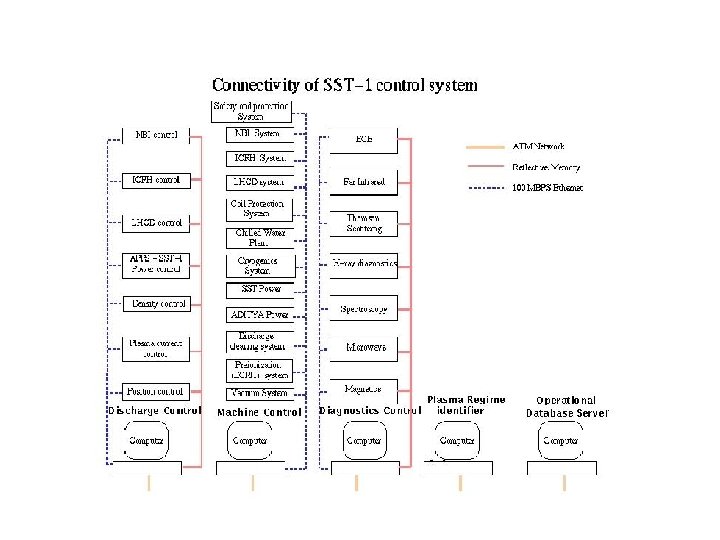
Implementation approach Hierarchical distributed control system. Supervisory central control at the top Supervising subsystems and exchanging status , parameters and commands Individual subsystems are directly controlled and monitored by its own dedicated intelligent control system For quicker and faster actions Interlocks and safety measures will be exercised by individual subsystem For batter and Efficient managements of the system entire control activity has been divided in following groups Machine Control system Discharge Control System Diagnostic Control System
Machine Control All the subsystem doing routine tasks like monitoring temp, water flow, vac pressure etc. are covered under machine control. Status and heath of all the subsystem will be monitored under the Machine control Down load of limit values and summary of status from subsystem Power Supply System Vacuum System Status of switch Yard Control of vacuum pumping system, TF currents on/off, sequencing gate valves, limit values, Partial pressure measurements TF current profiles Status of various components
Water Cooling System Number of cooling system Discharge cleaning system for passive plate divertor On/off, Copper coils Discharge currents OT cooling system temp alarm and limit sets water flow Cryogenics status water pressure etc Coil Protection and Monitoring system Status Limit values Auxiliary Heating system Status of LHCD, ICRH, NBI
Dynamic Discharge control System Due to long discharge time. . One has a option of changing the strategy online depending upon the situations Scheduled discharge phases can be dynamically changed… Includes Plasma Current, Shape, Position and Density Control
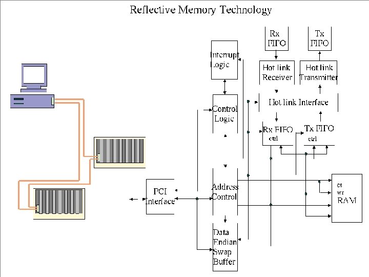
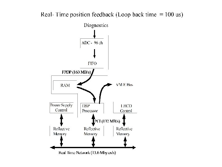
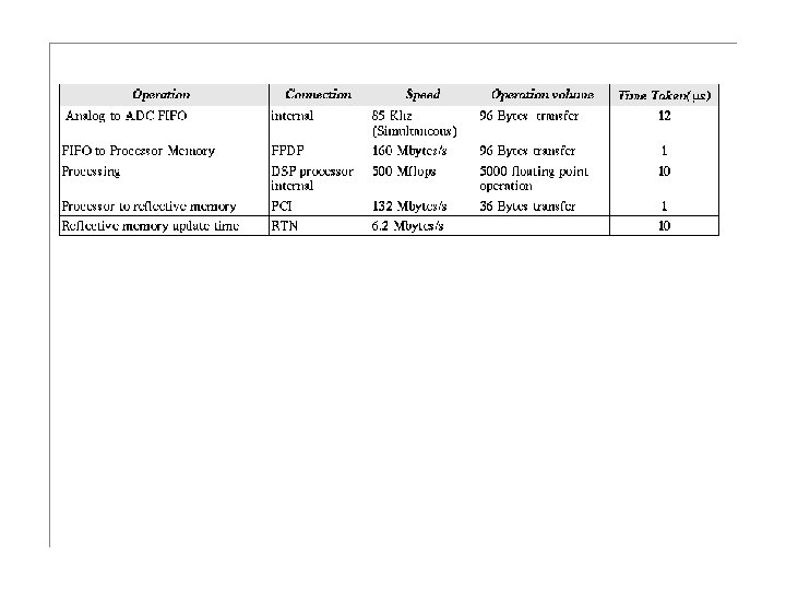
Position and Shape Control Target system Power. PC Real Time OS…. Vx. Works Position Control will be fast Reflective Memory Time scale of the order of 100 micro sec. for real time datainsharing Changing current copper Plasma Position and Shape Control conductor active Common algorithm to estimate the feed back coil Plasma Position and Shape Based on Function Parameterization code Relatively on slow time scale Constraint due to Super conductor PF Coils Rapid change of I is not permitted through PF due Quench And L/R ratio Signal from 48 Mag probes, Plasma Currents , Flux loops and coil currents to determine the shape & Position. Error in shape will be translated into correction PF current
Density and Plasma Current Control Electron density Ref. Density 10 ms time scale Gas Feed Piezo gate Valve Controller Plasma Microwave Fringe Interferometer Counter Plasma Current will be controlled By controlling the LHCD power Rogowski coils / Hall sensors 1 ms correction time scale
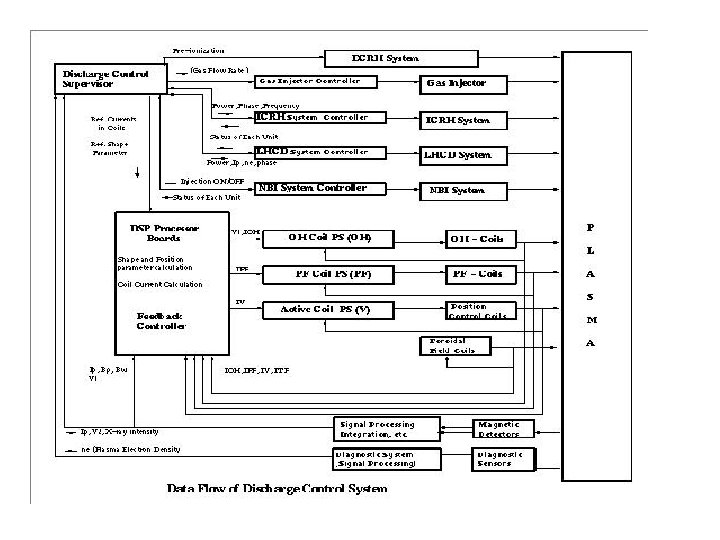
Control Overview
Software & H/W Platforms…. Windows Linux Real-time Linux Vx. Works Software Development Tools Lab Windows/CVI Lab. View TCL/TK MSSQL ORACLE EPICS Hardware CAMAC PXI VME Reflective Memory Processor Pentium Power. PC
Thanks…….