Sequence Diagram Sequence diagram is the most common


")


 is")

 is a")
")


- Slides: 30
Sequence Diagram
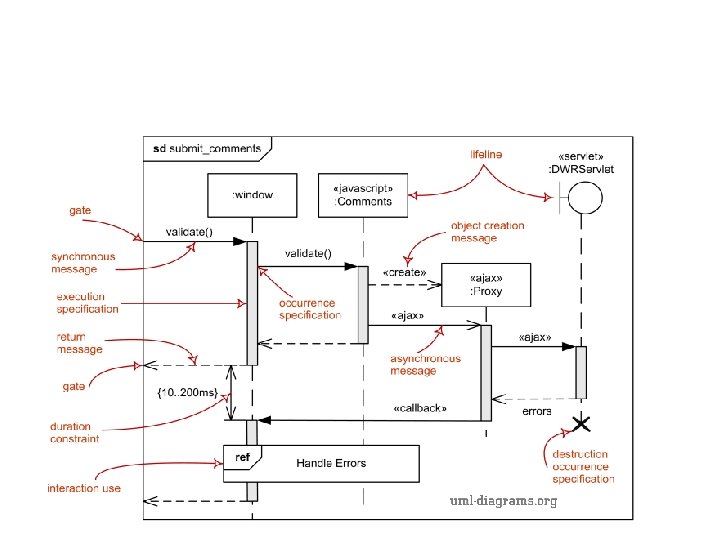
• Sequence diagram is the most common kind of interaction diagram, which focuses on the message interchange between a number of lifelines. • Sequence diagram describes an interaction by focusing on the sequence of messages that are exchanged, along with their corresponding occurrence specifications on the lifelines.
• The following nodes and edges are typically drawn in a UML sequence diagram: • lifeline, • execution specification, • message, • interaction fragment, • destruction occurrence.
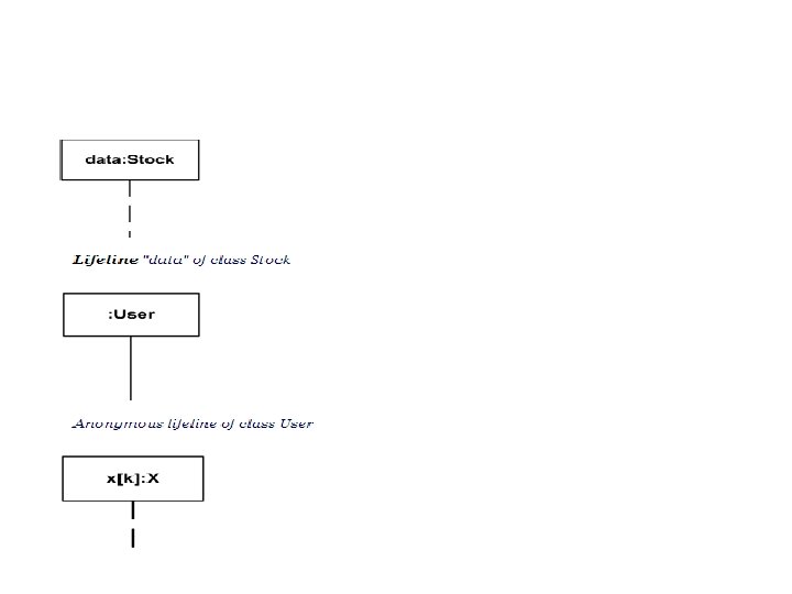
Lifeline • Lifeline is a named element which represents an individual participant in the interaction. While parts and structural features may have multiplicity greater than 1, lifelines represent only one interacting entity.
Message • Message is a named element that defines one specific kind of communication between lifelines of an interaction. The message specifies not only the kind of communication, but also the sender and the receiver. Sender and receiver are normally two occurrence specifications (points at the ends of messages).
Message • Depending on the type of action that was used to generate the message, message could be one of: • synchronous call • asynchronous call • create • delete • reply
• Synchronous call typically represents operation call - send message and suspend execution while waiting for response. Synchronous call messages are shown with filled arrow head.
• Asynchronous call - send message and proceed immediately without waiting for return value. Asynchronous messages have an open arrow head.
• Create Message • Create message is sent to a lifeline to create itself. It is shown as a dashed line with open arrowhead (looks the same as reply message), and pointing to the created lifeline's head.
• Delete Message • Delete message (called stop in previous versions of UML) is sent to terminate another lifeline. The lifeline usually ends with a cross in the form of an X at the bottom denoting destruction occurrence.
• Reply Message • Reply message to an operation call is shown as a dashed line with open arrow head (looks similar to creation message).
• Messages by Presence of Events • Depending on whether message send event and receive events are present, message could be one of: • complete message • lost message • found message
• The semantics of a complete message is the trace <send. Event, receive. Event>. Both send. Event and receive. Event are present.
• Lost Message is a message where the sending event is known, but there is no receiving event. It is interpreted as if the message never reached its destination. The semantics is the trace <send. Event>, receive. Event is absent. Lost messages are denoted with as a small black circle at the arrow end of the message.
• Found Message is a message where the receiving event is known, but there is no (known) sending event. It is interpreted as if the origin of the message is outside the scope of the description. This may for example be noise or other activity that we do not want to describe in detail. The semantics is simply the trace: <receive. Event>, while send event is absent.
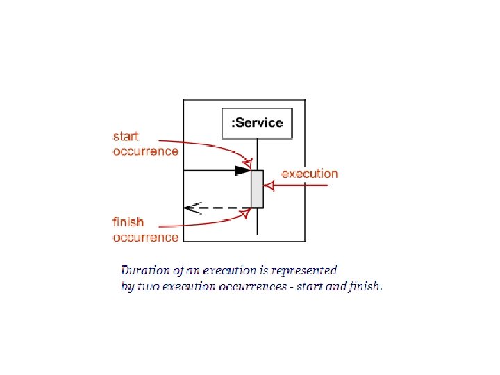
• Execution Occurrence • Execution occurrence (complete UML name execution occurrence specification) is an occurrence which represents moments in time at which actions or behaviours start or finish. • Execution occurrence references exactly one execution specification which describes the execution that is started or finished at this execution occurrence.
Communication Diagram
Communication Diagram • Communication diagram (called collaboration diagram in UML 1. x) is a kind of UML interaction diagram which shows interactions between objects and/or parts (represented as lifelines) using sequenced messages in a free-form arrangement.
• Communication diagram corresponds (i. e. could be converted to/from or replaced by) to a simple sequence diagram without structuring mechanisms such as interaction uses and combined fragments. • It is also assumed that message overtaking (i. e. , the order of the receptions are different from the order of sending of a given set of messages) will not take place or is irrelevant.
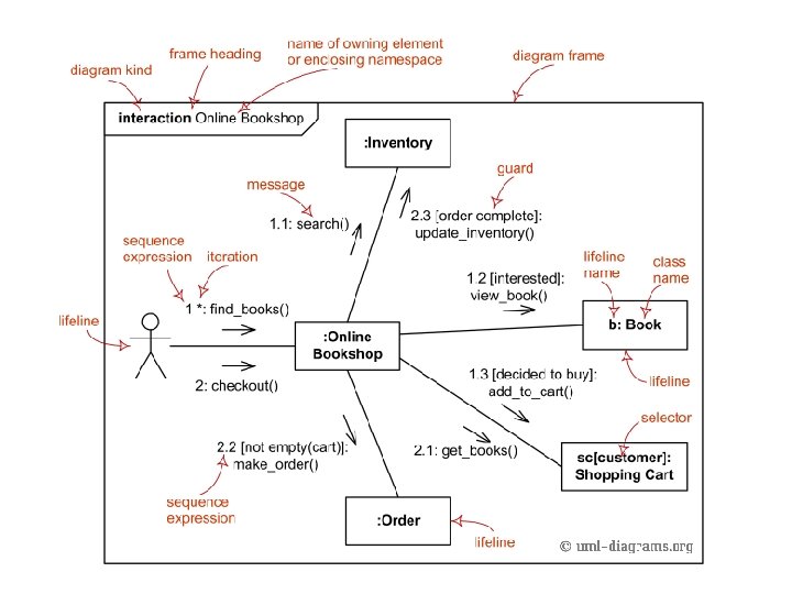
• The following nodes and edges are drawn in a UML communication diagrams: – frame, – lifeline, – message. These major elements of the communication diagram are shown on the picture below.
Frame • Communication diagrams could be shown within a rectangular frame with the name in a compartment in the upper left corner.
Lifeline • Lifeline is a specialization of named element which represents an individual participant in the interaction.
Lifeline
Message • Message in communication diagram is shown as a line with sequence expression and arrow above the line. • The arrow indicates direction of the communication.
Sequence Expression • The sequence expression is a dot separated list of sequence terms followed by a colon (": ") and message name after that: sequence-expression : : = sequenceterm '. '. . . ': ' message-name • For example, 3 b. 2. 2: m 5 contains sequence expression 3 b. 2. 2 and message name m 5.
Sequence Expression