Reflection and Transmission Asst Prof Dr zgr Tamer


must join")


 is given by")


 from air (n 1=1)")


")


 field can be written as (for")


- Slides: 87
Reflection and Transmission Asst. Prof. Dr. Özgür Tamer
Normal Incidence
Normal Incidence Incident wave Reflected Wave
Normal Incidence Transmitted wave
Normal Incidence At z=0 the combined fields on the left (incident and reflected)must join the fields on the right (transmitted) according to the boundary conditions For the normal incidence all components are parallel, so;
Normal Incidence For the magnetic field
Normal Incidence Reflected and Transmitted waves can be found as
Normal Incidence If the permeabilities are close to μ 0, then;
Normal Incidence The reflected wave is in phase if u 2>u 1 or out of phase otherwise The real amplitudes are given by;
Normal Incidence Energy: The Intensity (average power per unit area) is given by
Normal Incidence The ratio of the reflected intensity to the incident intensity is given by; And for the transmitted energy
Normal Incidence Г is called the reflection coefficient and T is called the transmission coefficient
Standing Wave Ratio The total electric field becomes For any media we can define a phase angle and a reflection coefficient
Standing Wave Ratio If the incident wave is given by And the reflected wave is The total field becomes
Standing Wave Ratio Since The total wave does not contain the factor it is a standing wave instead of a travelling wave. Etot(Z, t)=EI(Z, t)+ER(Z, t) There are planes in which Etot(Z, t) is minimum and maximum at all times
Standing Wave Ratio The instantaneous values of the two vectors are
Standing Wave Ratio
Standing Wave Ratio It increases with the increase of the magnitude of the reflection coefficient·
Oblique Incidence Oblique incidence is a more general term covering also Normal Incidence
Oblique Incidence Again we have an incident wave and the reflected wave becomes
Oblique Incidence While the transmitted wave is
Oblique Incidence The three wavenumbers are related by › Since Reflected and Incident angles are in the same medium
Oblique Incidence The combined fields in medium 1 Must be joined with the fields in medium 2 Boundary conditions must be satisfied all points on the plane
Oblique Incidence x, y and t dependence can be observed from the exponential parts t is already equal for all media And for the spatial terms
Oblique Incidence More explicitly
Oblique Incidence Lets be more specific and For this case kı lies in the x z plane as well as k. R and k. T Concluding: › The incident, reflected and transmitted wave vectors form a plane which also includes the normal to the surface
Oblique Incidence where θI is the angle of incidence, θR is the angle of reflection, and θT is the angle of transmission (more commonly known as the angle of refraction) all of them measured with respect to the normal
Oblique Incidence Law of reflection: The angle of incidence is equal to the angle of reflection › θ I = θ R. law of refraction—Snell’s law
Oblique Incidence Since we got rid of the exponential parts the boundary conditions become
Oblique Incidence If the polarization of the incident wave is parallel to the plane of incidence, reflected and transmitted waves are also polarized in the same plane Then we have using the first boundary condition
Oblique Incidence Since the magnetic fields have no z components the third boundary condition becomes The fourth equation
Oblique Incidence
Oblique Incidence These are known as Fresnel’s equations, for the case of polarization in the plane of incidence. › the transmitted wave is always in phase with the incident one › the reflected wave is either in phase if α > β, or 180◦ out of phase if α < β
Oblique Incidence The amplitudes of the transmitted and reflected waves depend on the angle of incidence, because α is a function of θI › In the case of normal incidence (θI=0), α=1 › At grazing incidence (θI= 90◦), α diverges, and the wave is totally reflected
Oblique Incidence Brewster’s Angle › at which the reflected wave is completely extinguished › this occurs when
Oblique Incidence For a typical case practical formulas
Oblique Incidence › light incident on glass (n 2=1. 5) from air (n 1=1)
Oblique Incidence The incident intensity is while the reflected and transmitted intensities are
Oblique Incidence The reflection and transmission coefficients for waves polarized parallel to the plane of incidence are
Oblique Incidence The reflection and transmission graphs vs angle of incidence (R=1+T)
Reflection at a Conducting Surface In case of free charges and currents the boundary conditions become Where is the free surface charge Kf is the free surface current and n is the normal vector
Reflection at a Conducting Surface For ohmic conductors there can be no free surface current since J is a volume current density which is a current per unit area perpendicular to the flow direction A surface current density is amps per unit length perpendicular to the flow. This 'length' is just a 1 -D line. . . it has no area. We set K=0 in the boundary conditions
Reflection at a Conducting Surface Suppose xy plane is a boundary between a dielectric and a conductor The incident wave is given by
Reflection at a Conducting Surface The incident wave gives rise to a reflected and a transmitted wave The transmitted wave is attenuated as it penetrates into the conductor
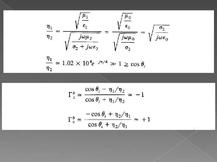
Reflection at a Conducting Surface Since on both sides, boundary condition yields Since Kf is zero
Reflection at a Conducting Surface And similarly we have For a perfect conductor The wave is totally reflected with a 180 degrees phase shift
Problem 1 Find the reflection and transmission coefficients for the interface between air and fresh water (E = 81ε 0, σ = 0), in the case of perpendicular incidence.
Problem 2 A plane wave is normally incident on the interface between air and a dielectric having a permeability μ= μo, and an unknown permittivity. The measured standing-wave ratio in air is 1. 8. Determine ε.
Problem 3 A plane wave with parallel polarization is incident at an angle of π/4 from air on a perfect dielectric with εr = 4 and μ = μo. Find the Fresnel coefficients. What fraction of the incident power is reflected, and what is transmitted into the dielectric?
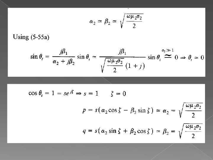
Reflection at a Conducting Surface Oblique Incidence › For lossy media Snell's law of refraction can be written as › For an dielectric and a lossy conductor interface we have
Reflection at a Conducting Surface By using a trigonometric identity The wave transmitted into the conductor becomes
Reflection at a Conducting Surface After some mathematical simplifications the transmitted electric field becomes where
Reflection at a Conducting Surface Instantaneous (time dependent) field can be written as (for a real Et) The angle of the transmitted wave is defined by φ2 instead of θT
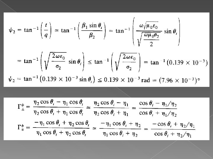
Reflection at a Conducting Surface φ2 can be evaluated by
Reflection at a Conducting Surface Transmitted wave equation for the new case with φ2 is given by; Where
Reflection at a Conducting Surface The phase velocity of the wave is given by;
Multiple Interfaces Normal Incidence › A uniform plane wave propagating in the z direction is normally incident onto the interface between regions 1 and 2 a second interface exists between regions 2 and 3
Multiple Interfaces For the first interface the reflection coefficient is given by; And for the second boundary we have
Multiple Interfaces
Multiple Interfaces
Multiple Interfaces By summing all the fields that resulted from the multiple reflection process the steadystate expressions can be obtained
Multiple Interfaces Region 1 › we have the incident wave propagating in the +z direction and an infinite number of reflected waves propagating in the –z direction
Multiple Interfaces The summation over the complex amplitudes of the infinite number of the reflected waves is just another complex representing the steady-state amplitude of the overall reflected wave
Multiple Interfaces Region 2 › In this region at steady state there will be an infinite number of waves propagating in the +z direction and an infinite number of other waves propagating in the –z direction.
Multiple Interfaces › A general expression for the steady state fields in region 2 is, therefore, given by
Multiple Interfaces Region 3 › All the transmitted waves in this region are propagating in the +z direction.
Multiple Interfaces
Multiple Interfaces Reflection Coefficient › For the previously defined dielectric slab at a distance z=-l from the boundary
Multiple Interfaces Just to the right of the boundary the input impedance in the +z is given by The input impedance at z=-l can be evaluated by
Multiple Interfaces Where
Multiple Interfaces Therefore This is also known as the impedance transfer equation
Multiple Interfaces The input impedance at z=0 is equal to the intrinsic impedance of medium 3 And the reflection coefficient at the same interface is given by
Multiple Interfaces At z=-d+ the input impedance can be written as And the input reflection coefficient az z=-dcan be expressed as
Multiple Interfaces
Multiple Interfaces We have defined individual reflection coefcients at each of the boundaries. The input reflection coefficient at z=-d- can also be written as
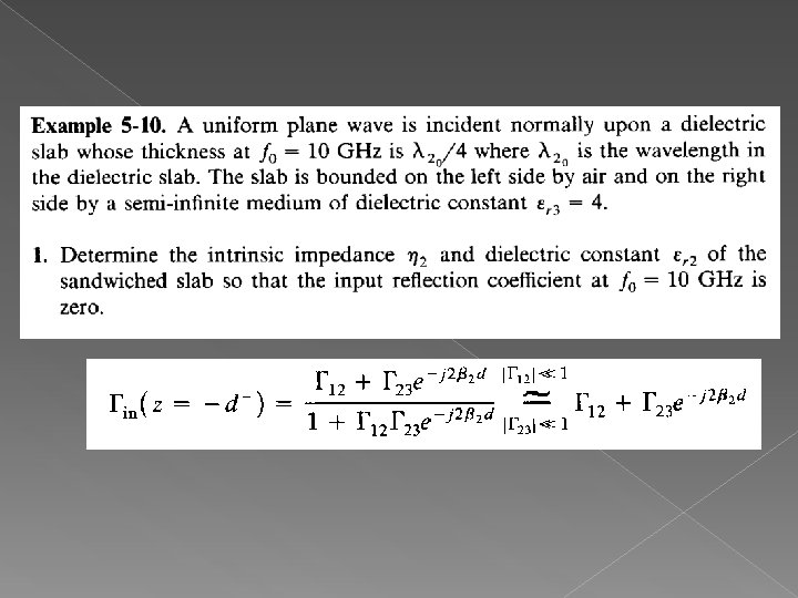
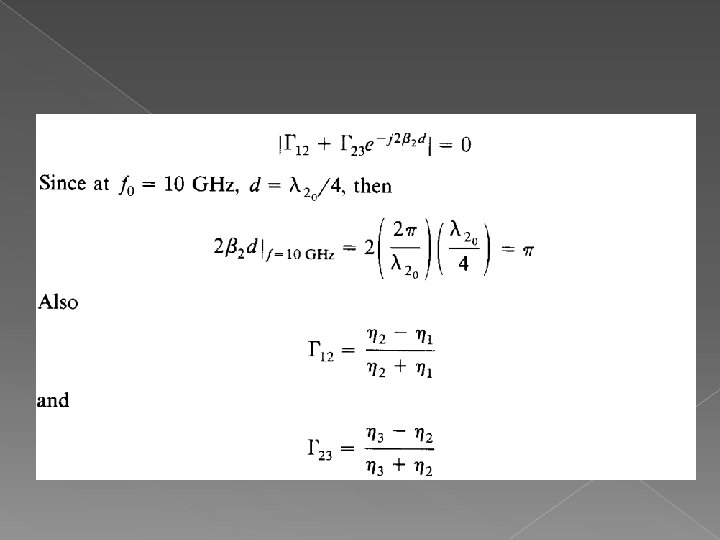
Multiple Interfaces Example: › A uniform plane wave at a frequency of 10 GHz is incident normally on a dielectric slab of thickness d and bounded on both sides of air. Assume that the relative dielectric constant of the slab is 2. 56. › Determine thickness of the slab so that the input reflection coefficient at 10 GHz is zero.
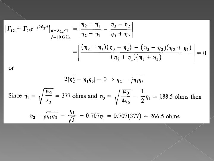
Multiple Interfaces For the input reflection coeflicient to be equal to zero, the reflection Coefficient must be set equal to zero. This can be accomplished if
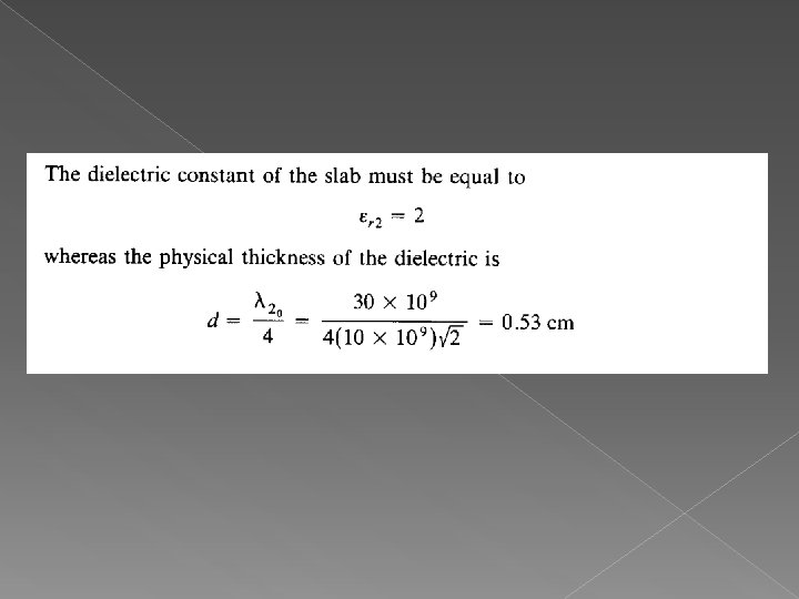
Multiple Interface The thickness must be Where λ 2 is the wavelength inside the dielectric slab
Multiple Interface The thickness of the slab must be an integral number of half wavelengths inside the dielectric; at 10 GHz the wavelength is
Problem 2