2160703 Computer Graphics Unit3 2 D Transformation Viewing


 ty (x, y) tx Unit: 3 2 D transformation &")


 (x, y) θ ∅ Unit: 3 2 D transformation &")
 (x, y) θ ∅ Unit: 3 2 D transformation")
 (x, y) θ ∅ Unit: 3 2 D transformation &")


 Clipping § By creating more regions around the clip window the")


- Slides: 109
2160703 Computer Graphics Unit-3 2 D Transformation & Viewing Prof. Vijay M. Shekhat 9558045778 vijay. shekhat@darshan. ac. in
Outline § § § Transformation Basic transformation Matrix representation and homogeneous coordinates Composite transformation Other transformation The viewing pipeline Viewing coordinate reference frame Window-to-viewport coordinate transformation Point clipping Line clipping Polygon clipping Unit: 3 2 D transformation & viewing 2 Darshan Institute of Engineering & Technology
Transformation § Changing Position, shape, size, or orientation of an object is known as transformation. Unit: 3 2 D transformation & viewing 3 Darshan Institute of Engineering & Technology
Basic Transformation § includes three transformations • Translation, • Rotation • Scaling. § These are known as basic transformation because with combination of them we can obtain any transformation. Unit: 3 2 D transformation & viewing 4 Darshan Institute of Engineering & Technology
Translation § (x', y') ty (x, y) tx Unit: 3 2 D transformation & viewing 5 Darshan Institute of Engineering & Technology
Contd. § Unit: 3 2 D transformation & viewing 6 Darshan Institute of Engineering & Technology
Translation Example § Unit: 3 2 D transformation & viewing 7 Darshan Institute of Engineering & Technology
Rotation § (x', y') (x, y) θ ∅ Unit: 3 2 D transformation & viewing 8 Darshan Institute of Engineering & Technology
Rotation Equation § (x', y') (x, y) θ ∅ Unit: 3 2 D transformation & viewing 9 Darshan Institute of Engineering & Technology
Contd. § (x', y') (x, y) θ ∅ Unit: 3 2 D transformation & viewing 10 Darshan Institute of Engineering & Technology
Rotation about arbitrary point § § Its matrix equation can be obtained by simple method. § Rotation is also rigid body transformation so we need to rotate each point of object. Unit: 3 2 D transformation & viewing 11 (x', y') (x, y) θ ∅ (xr, yr) Darshan Institute of Engineering & Technology
Rotation Example § Unit: 3 2 D transformation & viewing 12 Darshan Institute of Engineering & Technology
Scaling § Unit: 3 2 D transformation & viewing 13 Darshan Institute of Engineering & Technology
Contd. § 3 1 Unit: 3 2 D transformation & viewing 14 1 3 Darshan Institute of Engineering & Technology
Contd. § Uniform Scaling Unit: 3 2 D transformation & viewing Differential Scaling 15 Darshan Institute of Engineering & Technology
Fixed Point Scaling § Fixed Point Unit: 3 2 D transformation & viewing 16 Darshan Institute of Engineering & Technology
Fixed Point Scaling Equation § Unit: 3 2 D transformation & viewing 17 Darshan Institute of Engineering & Technology
Scaling Example § Unit: 3 2 D transformation & viewing 18 Darshan Institute of Engineering & Technology
Matrix Representation and Homogeneous Coordinates § Many graphics application involves sequence of geometric transformations. § For example in design and picture construction application we perform Translation, Rotation, and scaling to fit the picture components into their proper positions. § For efficient processing we will reformulate transformation sequences. Unit: 3 2 D transformation & viewing 19 Darshan Institute of Engineering & Technology
Contd. § Unit: 3 2 D transformation & viewing 20 Darshan Institute of Engineering & Technology
Contd. § Unit: 3 2 D transformation & viewing 21 Darshan Institute of Engineering & Technology
Contd. § Unit: 3 2 D transformation & viewing 22 Darshan Institute of Engineering & Technology
Homogeneous Matrix for Translation § Unit: 3 2 D transformation & viewing 23 Darshan Institute of Engineering & Technology
Homogeneous Matrix for Rotation § Unit: 3 2 D transformation & viewing 24 Darshan Institute of Engineering & Technology
Homogeneous Matrix for Scaling § Unit: 3 2 D transformation & viewing 25 Darshan Institute of Engineering & Technology
Composite Transformation § In practice we need to apply more than one transformations to get desired result. § It is time consuming to apply transformation one by one on each point of object. § So first we multiply all matrix of required transformations which is known as composite transformation matrix. § Than we use composite transformation matrix to transform object. § For column matrix representation, we form composite transformations by multiplying matrices from right to left. Unit: 3 2 D transformation & viewing 26 Darshan Institute of Engineering & Technology
Multiple Translations § Unit: 3 2 D transformation & viewing 27 Darshan Institute of Engineering & Technology
Contd. § Unit: 3 2 D transformation & viewing 28 Darshan Institute of Engineering & Technology
Multiple Translations Example § Unit: 3 2 D transformation & viewing 29 Darshan Institute of Engineering & Technology
Multiple Rotations § Unit: 3 2 D transformation & viewing 30 Darshan Institute of Engineering & Technology
Contd. § Unit: 3 2 D transformation & viewing 31 Darshan Institute of Engineering & Technology
Multiple Rotations Example § Unit: 3 2 D transformation & viewing 32 Darshan Institute of Engineering & Technology
Multiple Scaling § Unit: 3 2 D transformation & viewing 33 Darshan Institute of Engineering & Technology
Contd. § Unit: 3 2 D transformation & viewing 34 Darshan Institute of Engineering & Technology
Multiple Scaling Example § Unit: 3 2 D transformation & viewing 35 Darshan Institute of Engineering & Technology
General Pivot-Point Rotation § For rotating object about arbitrary point called pivot point we need to apply following sequence of transformation. 1. Translate the object so that the pivot-point coincides with the coordinate origin. 2. Rotate the object about the coordinate origin with specified angle. 3. Translate the object so that the pivot-point is returned to its original position (i. e. Inverse of step-1). Unit: 3 2 D transformation & viewing 36 Darshan Institute of Engineering & Technology
General Pivot-Point Rotation Equation § Unit: 3 2 D transformation & viewing 37 Darshan Institute of Engineering & Technology
Contd. § Unit: 3 2 D transformation & viewing 38 Darshan Institute of Engineering & Technology
General Pivot-Point Rotation Example § Unit: 3 2 D transformation & viewing 39 Darshan Institute of Engineering & Technology
Contd. § Unit: 3 2 D transformation & viewing 40 Darshan Institute of Engineering & Technology
Contd. § Unit: 3 2 D transformation & viewing 41 Darshan Institute of Engineering & Technology
General Fixed-Point Scaling § For scaling object with position of one point called fixed point will remains same, we need to apply following sequence of transformation. 1. Translate the object so that the fixed-point coincides with the coordinate origin. 2. Scale the object with respect to the coordinate origin with specified scale factors. 3. Translate the object so that the fixed-point is returned to its original position (i. e. Inverse of step-1). Unit: 3 2 D transformation & viewing 42 Darshan Institute of Engineering & Technology
General Fixed-Point Scaling Equation § Unit: 3 2 D transformation & viewing 43 Darshan Institute of Engineering & Technology
Contd. § Unit: 3 2 D transformation & viewing 44 Darshan Institute of Engineering & Technology
General Fixed-Point Scaling Example § Unit: 3 2 D transformation & viewing 45 Darshan Institute of Engineering & Technology
Contd. § Unit: 3 2 D transformation & viewing 46 Darshan Institute of Engineering & Technology
Contd. § Unit: 3 2 D transformation & viewing 47 Darshan Institute of Engineering & Technology
General Scaling Directions § Unit: 3 2 D transformation & viewing 48 Darshan Institute of Engineering & Technology
Contd. § Unit: 3 2 D transformation & viewing 49 Darshan Institute of Engineering & Technology
General Scaling Directions Equation § Unit: 3 2 D transformation & viewing 50 Darshan Institute of Engineering & Technology
Other Transformation § Some package provides few additional transformations which are useful in certain applications. § Two such transformations are: 1. Reflection 2. Shear. Unit: 3 2 D transformation & viewing 51 Darshan Institute of Engineering & Technology
1. Reflection § A reflection is a transformation that produces a mirror image of an object. § The mirror image for a two –dimensional reflection is generated relative to an axis of reflection by rotating the object 180 o about the reflection axis. § Reflection gives image based on position of axis of reflection. Transformation matrix for few positions are discussed here. Unit: 3 2 D transformation & viewing 52 Darshan Institute of Engineering & Technology
Reflection About X-Axis y § 1 2 3 2’ 53 x 3’ 1’ Unit: 3 2 D transformation & viewing Original Position Reflected Position Darshan Institute of Engineering & Technology
Reflection About Y-Axis § 1’ Reflected Position 3’ 1 2’ 2 Original Position 3 Unit: 3 2 D transformation & viewing 54 Darshan Institute of Engineering & Technology
Reflection About Origin § Original Position Reflected Position Unit: 3 2 D transformation & viewing 55 Darshan Institute of Engineering & Technology
Reflection About X = Y Line § Reflected Position Original Position Unit: 3 2 D transformation & viewing 56 Darshan Institute of Engineering & Technology
Reflection About X = - Y Line § Original Position Reflected Position Unit: 3 2 D transformation & viewing 57 Darshan Institute of Engineering & Technology
Reflection Example § Unit: 3 2 D transformation & viewing 58 Darshan Institute of Engineering & Technology
2. Shear § Unit: 3 2 D transformation & viewing 59 Darshan Institute of Engineering & Technology
§ Before Shear Unit: 3 2 D transformation & viewing 60 After Shear Darshan Institute of Engineering & Technology
Contd. § Before Shear Unit: 3 2 D transformation & viewing 61 After Shear Darshan Institute of Engineering & Technology
§ Unit: 3 2 D transformation & viewing 62 Darshan Institute of Engineering & Technology
Contd. § Unit: 3 2 D transformation & viewing 63 Darshan Institute of Engineering & Technology
§ Before Shear Unit: 3 2 D transformation & viewing 64 After Shear Darshan Institute of Engineering & Technology
Contd. § Before Shear Unit: 3 2 D transformation & viewing 65 After Shear Darshan Institute of Engineering & Technology
§ Unit: 3 2 D transformation & viewing 66 Darshan Institute of Engineering & Technology
Contd. § Unit: 3 2 D transformation & viewing 67 Darshan Institute of Engineering & Technology
Window and Viewport § Window: Area selected in world-coordinate for display is called window. It defines what is to be viewed. § Viewport: Area on a display device in which window image is display (mapped) is called viewport. It defines where to display. Window YWmax Viewport YVmax YWmin YVmin XWmin Unit: 3 2 D transformation & viewing XWmax 68 XVmin XVmax Darshan Institute of Engineering & Technology
The Viewing Pipeline § In many case window and viewport are rectangle, also other shape may be used as window and viewport. § In general finding device coordinates of viewport from word coordinates of window is called as viewing transformation. § Sometimes we consider this viewing transformation as window-to -viewport transformation but in general it involves more steps. § Let’s see steps involved in viewing pipeline. Unit: 3 2 D transformation & viewing 69 Darshan Institute of Engineering & Technology
Contd. MC Construct World. Coordinate Scene Using Modeling. Coordinate Transformations WC Convert World -Coordinate to Viewing Coordinates NVC Map Normalized Viewport to Device Coordinates VC Map Viewing Coordinate to Normalized Viewing Coordinates using Window-Viewport Specifications Unit: 3 2 D transformation & viewing 70 DC Darshan Institute of Engineering & Technology
Viewing Coordinate Reference Frame § We can obtain reference frame in any direction and at any position. § For handling such condition • first of all we translate reference frame origin to standard reference frame origin. • Then we rotate it to align it to standard axis. Unit: 3 2 D transformation & viewing 71 Darshan Institute of Engineering & Technology
Window-To-Viewport Coordinate Transformation § Mapping of window coordinate to viewport is called window to viewport transformation. § We do this using transformation that maintains relative position of window coordinate into viewport. § That means center coordinates in window must be remains at center position in viewport. Window YWmax YW YVmax XW YWmin Viewport YV XV YVmin XWmin Unit: 3 2 D transformation & viewing XWmax 72 XVmin XVmax Darshan Institute of Engineering & Technology
Contd. § Window YWmax YW YVmax XW YWmin Viewport YV XV YVmin XWmin Unit: 3 2 D transformation & viewing XWmax 73 XVmin XVmax Darshan Institute of Engineering & Technology
Contd. § Unit: 3 2 D transformation & viewing 74 Darshan Institute of Engineering & Technology
Contd. § Unit: 3 2 D transformation & viewing 75 Darshan Institute of Engineering & Technology
Contd. § Unit: 3 2 D transformation & viewing 76 Darshan Institute of Engineering & Technology
Contd. § For each display device we can use different window to viewport transformation. This mapping is known as workstation transformation. § Also we can use two different displays devices and we map different window-to-viewport on each one. Normalized Space Viewport WS 1 Viewport WS 2 Viewport Monitor 2 Monitor 1 WS 1 Window Unit: 3 2 D transformation & viewing 77 WS 2 Window Darshan Institute of Engineering & Technology
Clipping § Any procedure that identifies those portions of a picture that are either inside or outside of a specified region of space is referred to as a clipping algorithm, or simply clipping. § The region against which an object is to clip is called a clip window. § Clip window can be general polygon or it can be curved boundary. Unit: 3 2 D transformation & viewing 78 Darshan Institute of Engineering & Technology
Application of Clipping § It can be used for displaying particular part of the picture on display screen. § Identifying visible surface in 3 D views. § Antialiasing. § Creating objects using solid-modeling procedures. § Displaying multiple windows on same screen. § Drawing and painting. Unit: 3 2 D transformation & viewing 79 Darshan Institute of Engineering & Technology
Point Clipping § Clipping Window ywmax ywmin xwmax Full Screen Unit: 3 2 D transformation & viewing 80 Darshan Institute of Engineering & Technology
Line Clipping § Line clipping involves several possible cases. 1. Completely inside the clipping window. 2. Completely outside the clipping window. 3. Partially inside and partially outside the clipping window. Clipping Window Full Screen Unit: 3 2 D transformation & viewing 81 Darshan Institute of Engineering & Technology
Line Clipping § For line clipping several scientists tried different methods to solve this clipping procedure. § Some of them we will discuss. Which are: 1. Cohen-Sutherland Line Clipping 2. Liang-Barsky Line Clipping 3. Nicholl-Lee-Nicholl Line Clipping Unit: 3 2 D transformation & viewing 82 Darshan Institute of Engineering & Technology
Region Code in Cohen-Sutherland Line Clipping § This is one of the oldest and most popular line-clipping procedures. § In this we divide whole space into nine region and give 4 bit region code. § Code is deriving by: 1 0 0 1 1 0 0 0 1 0 Clipping Window 0 0 0 1 0 0 • Set bit 1: For left side of clipping window. • Set bit 2: For right side of clipping window. 0 1 0 0 0 1 1 0 0 1 • Set bit 3: For below clipping window. • Set bit 4: For above clipping window. Put all other zero (Reset remaining bit) Unit: 3 2 D transformation & viewing 83 Darshan Institute of Engineering & Technology
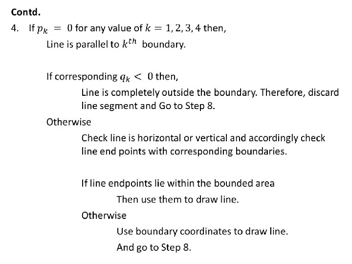
Steps Cohen-Sutherland Line Clipping Step-1: Assign region code to both endpoint of a line depending on the position where the line endpoint is located. Step-2: If both endpoint have code ‘ 0000’ Then line is completely inside. Otherwise Perform logical ending between this two codes. If result of logical ending is non-zero Line is completely outside the clipping window. Otherwise Calculate the intersection point with the boundary one by one. Divide the line into two parts from intersection point. Repeat from Step-1 for both line segments. Step-3: Draw line segment which are completely inside and eliminate other line segment which found completely outside.
Intersection points- Cohen. Sutherland Algorithm § Unit: 3 2 D transformation & viewing 85 Darshan Institute of Engineering & Technology
Contd. § Unit: 3 2 D transformation & viewing 86 Darshan Institute of Engineering & Technology
Liang-Barsky Line Clipping § Unit: 3 2 D transformation & viewing 87 Darshan Institute of Engineering & Technology
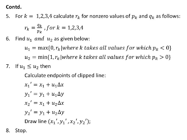
Liang-Barsky Line Clipping Algorithm § Unit: 3 2 D transformation & viewing 88 Darshan Institute of Engineering & Technology
Advantages of Liang-Barsky Line Clipping § Unit: 3 2 D transformation & viewing 91 Darshan Institute of Engineering & Technology
Nicholl-Lee-Nicholl Line (NLN) Clipping § By creating more regions around the clip window the NLN algorithm avoids multiple clipping of an individual line segment. § In Cohen-Sutherlan line clipping sometimes multiple calculation of intersection point of a line is done before actual window boundary intersection. § These multiple intersection calculation is avoided in NLN line clipping procedure. § NLN line clipping perform the fewer comparisons and divisions so it is more efficient. § But NLN line clipping cannot be extended for three dimensions. Unit: 3 2 D transformation & viewing 92 Darshan Institute of Engineering & Technology
Contd. § For given line we find first point falls in which region out of nine region shown in figure. § Only three region are considered which are. • Window region • Edge region • Corner region § If point falls in other region than we transfer that point in one of the three region by using transformations. § We can also extend this procedure for all nine regions. Unit: 3 2 D transformation & viewing 93 Darshan Institute of Engineering & Technology
Dividing Region in NLN § T L R LT B L L LR L LB Unit: 3 2 D transformation & viewing 94 Darshan Institute of Engineering & Technology
Contd. § L TR L LR T TR LB TB LB Unit: 3 2 D transformation & viewing T 95 Darshan Institute of Engineering & Technology
Finding Region of Given Line in NLN § LT L L LR L LB Unit: 3 2 D transformation & viewing 96 Darshan Institute of Engineering & Technology
Contd. § LT L L LR L LB Unit: 3 2 D transformation & viewing 97 Darshan Institute of Engineering & Technology
Intersection Calculation in NLN § Unit: 3 2 D transformation & viewing 98 Darshan Institute of Engineering & Technology
Contd. § Unit: 3 2 D transformation & viewing 99 Darshan Institute of Engineering & Technology
Polygon Clipping § For polygon clipping we need to modify the line clipping procedure. § In line clipping we need to consider about only line segment. § In polygon clipping we need to consider the area and the new boundary of the polygon after clipping. § Various algorithm available for polygon clipping are: 1. Sutherland-Hodgeman Polygon Clipping 2. Weiler-Atherton Polygon Clipping etc. Unit: 3 2 D transformation & viewing 100 Darshan Institute of Engineering & Technology
Sutherland-Hodgeman Polygon Clipping § For correctly clip a polygon we process the polygon boundary as a whole against each window edge. § This is done by whole polygon vertices against each clip rectangle boundary one by one. in Left Clipper Right Clipper Unit: 3 2 D transformation & viewing 101 Bottom Clipper Top Clipper out Darshan Institute of Engineering & Technology
Processing Steps § We process vertices in sequence as a closed polygon. Inside Outside A D § Four possible cases are there. B C 1. If both vertices are inside the window we add only second vertices to output list. 2. If first vertices is inside the boundary and second vertices is outside the boundary only the edge intersection with the window boundary is added to the output vertex list. 3. If both vertices are outside the window boundary nothing is added to window boundary. 4. first vertex is outside and second vertex is inside the boundary, then adds both intersection point with window boundary, and second vertex to the output list. Unit: 3 2 D transformation & viewing 102 Darshan Institute of Engineering & Technology
Example 2 1’ 3 2’ 4 1 6 5 § As shown in figure we clip against left boundary. § Vertices 1 and 2 are found to be on the outside of the boundary. § Then we move to vertex 3, which is inside, we calculate the intersection and add both intersection point and vertex 3 to output list. Unit: 3 2 D transformation & viewing 103 Darshan Institute of Engineering & Technology
Contd. 2 1’ 3 2’ 3’ 4 1 6 5’ 4’ 5 § Then we move to vertex 4 in which vertex 3 and 4 both are inside so we add vertex 4 to output list. § Similarly from 4 to 5 we add 5 to output list. § From 5 to 6 we move inside to outside so we add intersection pint to output list. § Finally 6 to 1 both vertex are outside the window so we does not add anything. Unit: 3 2 D transformation & viewing 104 Darshan Institute of Engineering & Technology
Limitatin of Sutherlan-Hodgeman Algorithm § It may not clip concave polygon properly. V 2 V 1 V 3 V 4 V 5 V 6 § One possible solution is to divide polygon into numbers of small convex polygon and then process one by one. § Another approach is to use Weiler-Atherton algorithm. Unit: 3 2 D transformation & viewing 105 Darshan Institute of Engineering & Technology
Weiler-Atherton Polygon Clipping § It modifies Sutherland-Hodgeman vertex processing procedure for window boundary so that concave polygon also clip correctly. § This can be applied for arbitrary polygon clipping regions as it is developed for visible surface identification. § Procedure is similar to Sutherland-Hodgeman algorithm. § Only change is sometimes need to follow the window boundaries Instead of always follow polygon boundaries. § For clockwise processing of polygon vertices we use the following rules: 1. For an outside to inside pair of vertices, follow the polygon boundary. 2. For an inside to outside pair of vertices, follow the window boundary in a clockwise direction. Unit: 3 2 D transformation & viewing 106 Darshan Institute of Engineering & Technology
Example V 1’ V 1 V 4’ V 2 V 3’ V 4 V 5 V 6 § Start from v 1 and move clockwise towards v 2 and add intersection point and next point to output list by following polygon boundary, § then from v 2 to v 3 we add v 3 to output list. § From v 3 to v 4 we calculate intersection point and add to output list and follow window boundary. Unit: 3 2 D transformation & viewing 107 Darshan Institute of Engineering & Technology
Contd. V 1’ V 1 V 4’ V 2 V 3’ V 4 V 6 V 5’ V 7’ V 5 V 6’ § Similarly from v 4 to v 5 we add intersection point and next point and follow the polygon boundary, § next we move v 5 to v 6 and add intersection point and follow the window boundary, and § finally v 6 to v 1 is outside so no need to add anything. § This way we get two separate polygon section after clipping. Unit: 3 2 D transformation & viewing 108 Darshan Institute of Engineering & Technology
Thank You