Quick Logic Sp DE Quick Logic Icon Quick

,接著點選 Quick. Logic")

 -- Full_Adder. vhd 一個位元全加器的 VHDL電路描述檔 library ieee; use ieee.")
")


")


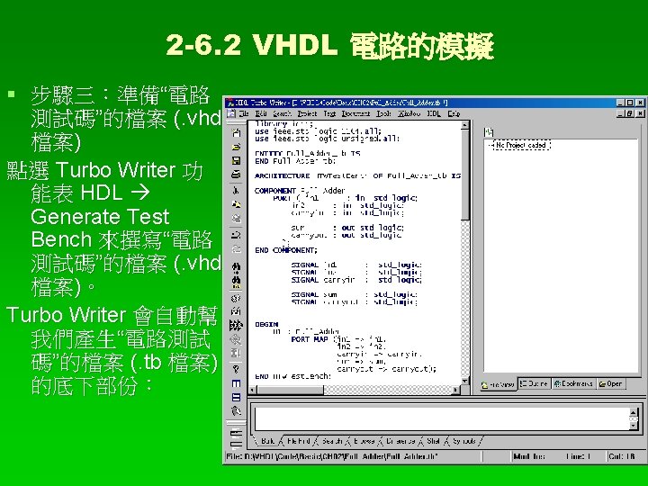
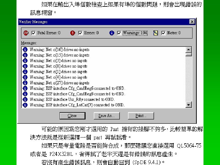
、佈侷 (Placement) 與繞線 (Routing) 步驟八:準備“電路測試碼”的檔案 (. vhd檔案) 電路模擬結果的波型變化與預期的結果一樣之後,請回到 Sp.")

 請全部勾選Auto Place & Route、Post-Layout Tools")
")
,接著點選 Quick. Pro 群組中的 Quick.")

 --- 使用 Synopsys 的 Designer Analyzer")
 階段 § 1. VHDL 電路描述檔案 (*. vhd 檔) § 我們將 VHDL 電路描述檔案")
- Slides: 84
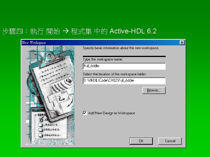
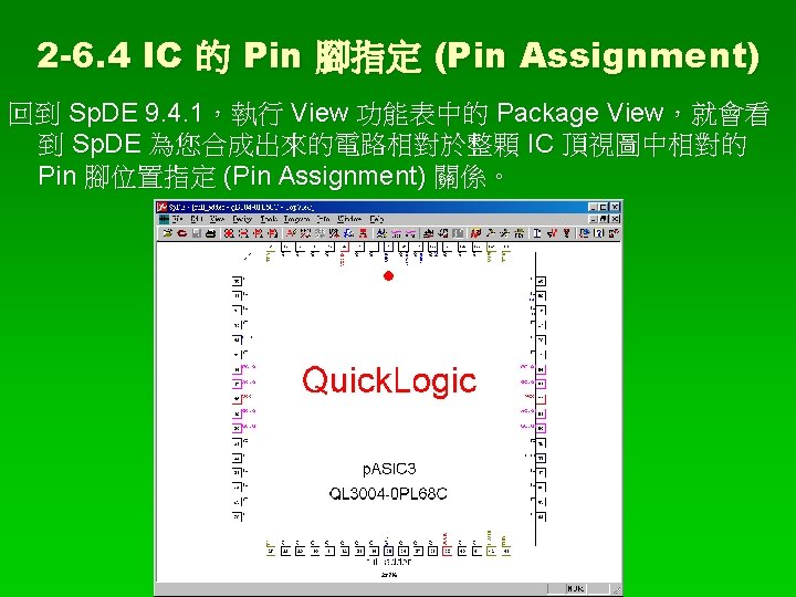
執行 Quick. Logic 群組中的 Sp. DE § 點選在桌面上有一個 Quick. Logic 的資料夾圖示 (Icon),接著點選 Quick. Logic 群組中的 Sp. DE (Sp. DE 9. 4. 1 Release Build Eval Copyright © 1993 -2003 Quick. Logic)。
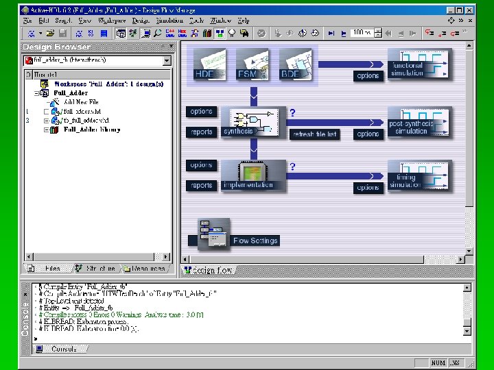
以一個位元的全加器電路作為 Model. Sim 電路模擬的 整個流程 § 步驟一:設計一個位元全加器電路的 vhdl 檔案 § 一個位元全加器電路的 VHDL 套件 (vhdl 檔案之一) -- pkg_Full_Adder. vhd 一個位元全加器的 VHDL套件 library ieee; use ieee. std_logic_1164. all; package pkg_Full_Adder is component Full_Adder port( in 1 : in std_logic; in 2 : in std_logic; carryin : in std_logic; sum : out std_logic; carryout : out std_logic ); end component; end pkg_Full_Adder;
一個位元全加器電路的 VHDL 電路描述檔 (vhdl 檔案之二) -- Full_Adder. vhd 一個位元全加器的 VHDL電路描述檔 library ieee; use ieee. std_logic_1164. all; use ieee. std_logic_unsigned. all; use work. pkg_Full_Adder. all; entity Full_Adder is port( in 1 : in std_logic; in 2 : in std_logic; carryin : in std_logic; sum : out std_logic; carryout : out std_logic ); end Full_Adder;
architecture arc of Full_Adder is begin Do_Full_Adder: process( in 1, in 2, carryin ) variable result : std_logic_vector( 1 downto 0); begin result : = '0'&in 1 + in 2 + carryin; carryout <= result(1); sum <= result(0); end process Do_Full_Adder; end arc;
library ieee; use ieee. std_logic_1164. all; use ieee. std_logic_unsigned. all; ENTITY Full_Adder_tb IS END Full_Adder_tb; ARCHITECTURE HTWTest. Bench OF Full_Adder_tb IS COMPONENT Full_Adder PORT ( in 1 : in std_logic; in 2 : in std_logic; carryin : in std_logic; sum : out std_logic; carryout : out std_logic ); END COMPONENT;
SIGNAL in 1 : std_logic; SIGNAL in 2 : std_logic; SIGNAL carryin : std_logic; SIGNAL sum : std_logic; SIGNAL carryout : std_logic; BEGIN U 1 : Full_Adder PORT MAP (in 1 => in 1, in 2 => in 2, carryin => carryin, sum => sum, carryout => carryout); process begin
-- 時間為 0 ns in 1 <= '0'; in 2 <= '0'; carryin <= '0'; wait for 20 ns; -- 時間為 20 ns in 1 <= '0'; in 2 <= '0'; carryin <= '1'; wait for 20 ns; -- 時間為 40 ns in 1 <= '0'; in 2 <= '1'; carryin <= '0'; wait for 20 ns; -- 時間為 60 ns in 1 <= '0'; in 2 <= '1'; carryin <= '1'; wait for 20 ns; -- 時間為 80 ns in 1 <= '1'; in 2 <= '0'; carryin <= '0'; wait for 20 ns; -- 時間為 100 ns in 1 <= '1'; in 2 <= '0'; carryin <= '1'; wait for 20 ns;
-- 時間為 120 ns in 1 <= '1'; in 2 <= '1'; carryin <= '0'; wait for 20 ns; -- 時間為 140 ns in 1 <= '1'; in 2 <= '1'; carryin <= '1'; wait for 20 ns; -- 時間為 160 ns assert false report " End of Simulation" severity failure; end process; END HTWTest. Bench;
Add existing resource files
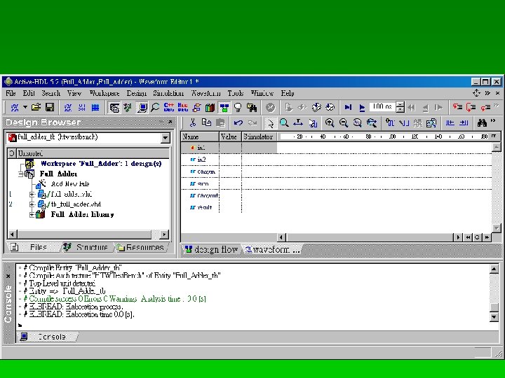
File New Waveform
Add Signals…
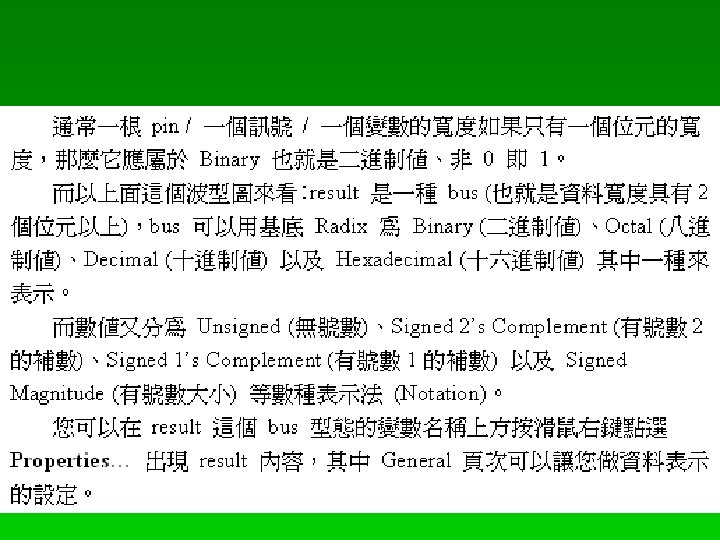
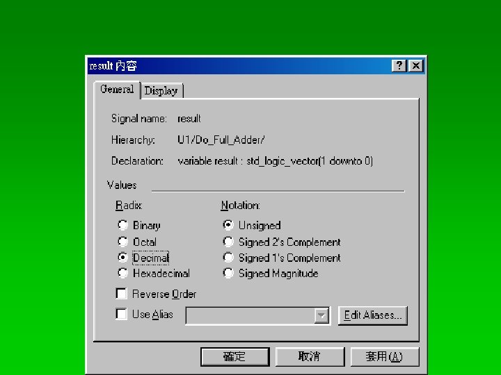
variable (變數)
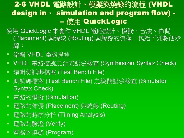
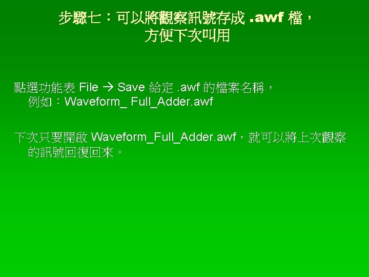
Full_Adder. vhd 的模擬結果
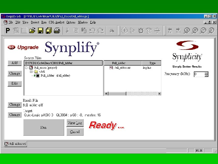
2 -6. 3 VHDL 電路的合成 (Synthesis)、佈侷 (Placement) 與繞線 (Routing) 步驟八:準備“電路測試碼”的檔案 (. vhd檔案) 電路模擬結果的波型變化與預期的結果一樣之後,請回到 Sp. DE,接著要讀入 VHDL 檔案,請點選主選單中的 File Import VHDL. . . 找到 Full_Adder. vhd 接著會自動啟動 Synplify-Lite, Synplify-Lite for Quick. Logic 7. 2. 1 Built: Dec 4 2002, Copyright © 1994 -2002 Synplicity, Inc. All Rights Reserved. VHDL and Verilog Synthesis for Quick. Logic FPGAs. 專門對 VHDL / Verilog 電路描述作編譯、 合成 (Synthesis)、佈侷 (Placement) 與繞線 (Routing) 的功 能。
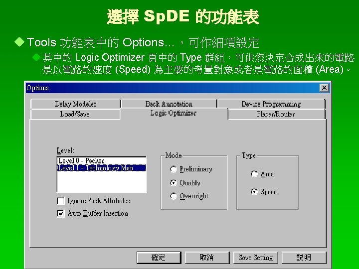
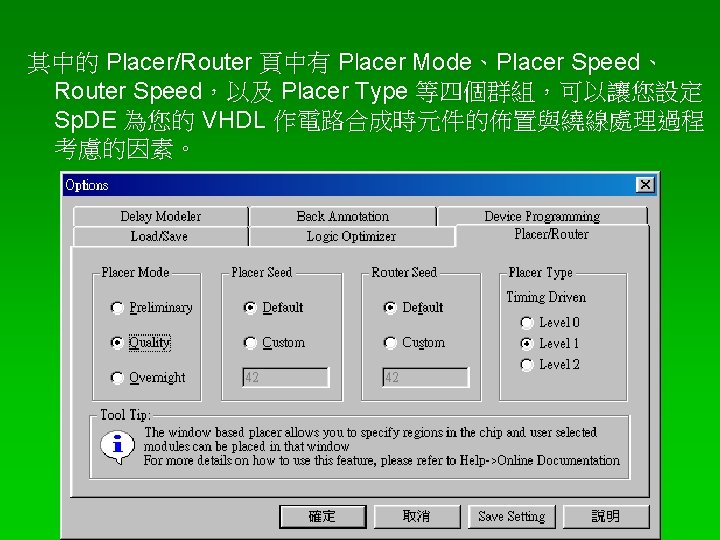
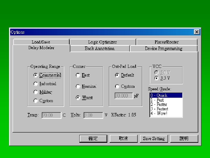
選擇 Synplify-Lite 的功能表 Options 功能表裡頭的 Configure VHDL Compiler…
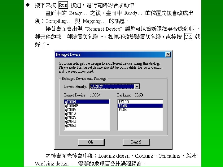
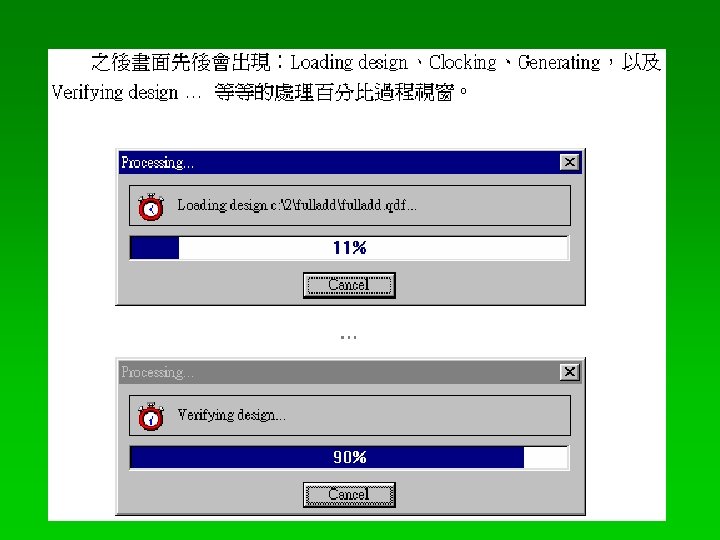
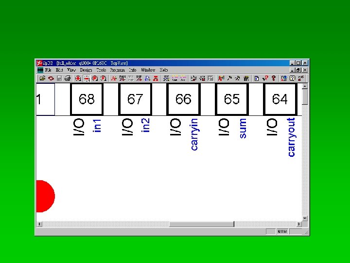
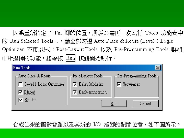
執行 Tools 功能表中的 Run Selected Tools… (也可以按Ctrl + R) 請全部勾選Auto Place & Route、Post-Layout Tools 以及 Pre. Programming Tools 群組中所選擇的功能,接著按 Run 按鈕開 始執行。
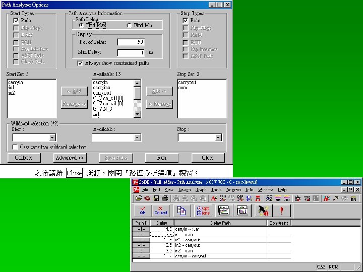
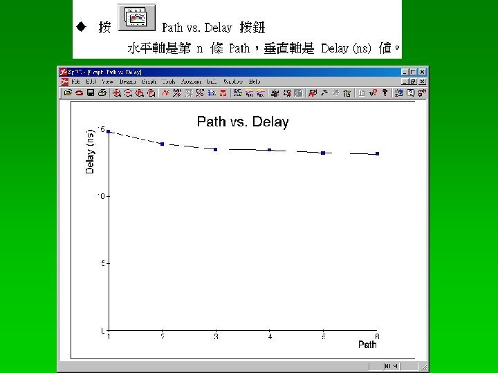
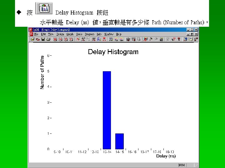
2 -6. 5 電路的路徑分析 (Path Analyzer)
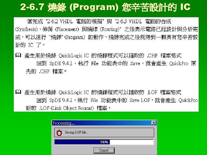
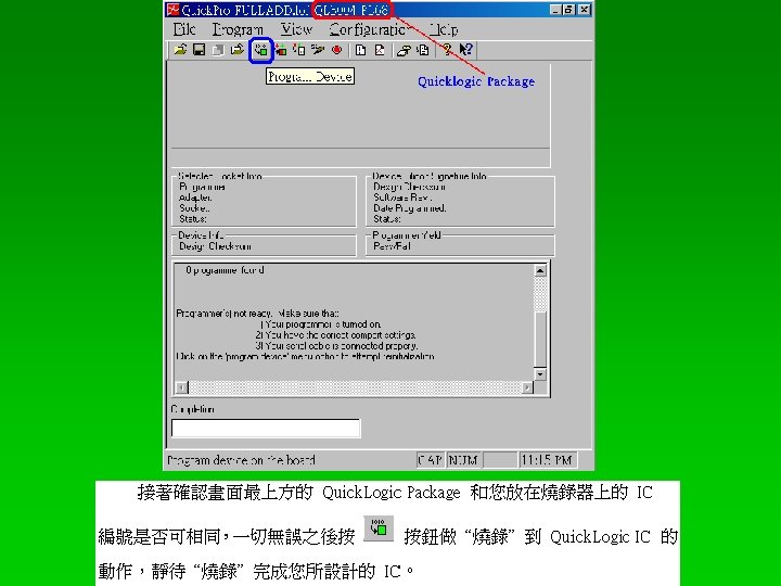
執行用於燒錄 Quick. Logic IC 的燒錄程式 點選在桌面上有一個 Quick. Pro 的資料夾圖示 (Icon),接著點選 Quick. Pro 群組中的 Quick. Pro (Quick. Pro 9. 1 RC 3 f Copyright © 2002 Quick. Logic)。
Synopsys 的 Design Analyzer 之 Primitive Cell 為:最基本的 「邏輯閘」元件,以及 Synopsys 公司所提供的 Cells § Synopsys 的 Design Analyzer 之 Primitive Cell 能夠合成出基 本的組合電路 (Combinational circuit),再配合記憶體元件則 能夠合成出基本的循序電路 (Sequential circuit)。 § 可合成的 (Synthesizable) VHDL primitives cells,包括下列的 基本元件: § not、and、nand、or、nor § xor、xnor Synopsys 公司所提供的 Cells:包括很多種加法、減法、乘法 … 等等的元件。
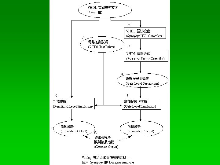
2 -8 VHDL 電路合成與模擬的流程 (Synthesis and Simulation Flow) --- 使用 Synopsys 的 Designer Analyzer § 使用 Synopsys 的 Design Analyzer 來將 VHDL 元件實作電路 合成與模擬的流程 (Synthesis and Simulation Flow)、如圖「 VHDL 元件合成與模擬的流程 --- 使用 Synopsys 的 Designer Analyzer」所示,分成 : § 「功能模擬」 (Functional Simulation) 階段 § 「邏輯閘層次模擬」 (Gate Level Simulation) 階段 § 「模擬結果」比較 (Simulation Output Comparison) 階段
「功能模擬」(Functional Simulation) 階段 § 1. VHDL 電路描述檔案 (*. vhd 檔) § 我們將 VHDL 電路描述檔案 (*. vhd 檔) 作為設計的輸入。 § 6. 功能模擬 (Functional Simulation) 及 7. 電路的測試碼 (VHDL Test Driver) § 「邏輯閘層次模擬」(Gate Level Simulation) 階段 § § § 1. VHDL 電路描述檔案 (*. vhd 檔) 2. VHDL 語法檢查 (Synopsys HDL Compiler) 3. VHDL 電路合成 (Synopsys Design Compiler) 4. 邏輯閘層次描述 (Gate Level Description) 5. 邏輯閘層次模擬 (Gate Level Simulation) 及 7. 電路的測試碼 (VHDL Test Driver) § 「模擬結果比較」 (Simulation Output Comparison) 階段 § 8. 功能及時序模擬結果比較 (Compare Output)