Outline q Solar Water Heating Systems Solar Collectors


![Cont’d … • • AAi. T Absorptivity of panel [ - ] αp Transmisivity Cont’d … • • AAi. T Absorptivity of panel [ - ] αp Transmisivity](https://slidetodoc.com/presentation_image_h2/4898738608066bfeb4485606a9a1c3f9/image-70.jpg)


- Slides: 85

Outline q Solar Water Heating Systems § Solar Collectors § Solar Water Heater § Thermal design Procedures/Process heat transfer analysis for Solar water heating systems q Solar Air Heating Systems § Solar Driers § Thermal design Procedures/Process heat transfer analysis for Solar air heating systems q Solar Thermal Power Plants q Solar Desalination § Solar Driers § Equivalent thermal resistance circuit for solar desalination for thermal analysis of the system AAi. T School of Mechanical and Industrial Engineering - SMIE 2

Solar Collector • A solar collector is a special kind of heat exchanger that transforms solar radiant energy into heat. • A solar collector differs in several respects from more conventional heat exchangers. • The latter usually accomplish a fluid-to-fluid exchange with high heat transfer rates and with radiation as an unimportant factor. In the solar collector, energy transfer is from a distant source of radiant energy to a fluid. • Flat-plate collectors can be designed for applications requiring energy delivery at moderate temperatures, up to perhaps 100◦C above ambient temperature. • They use both beam and diffuse solar radiation, do not require tracking of the sun, and require little maintenance. • They are mechanically simpler than concentrating collectors. The major applications of these units are in solar water heating, building heating, air conditioning, and industrial process heat. AAi. T School of Mechanical and Industrial Engineering - SMIE 3

Solar Collector AAi. T School of Mechanical and Industrial Engineering - SMIE 4

Solar Collector • The important parts of a typical liquid heating flat-plate solar collector, as shown in fig 6. 1, are the ‘‘black’’ solar energy-absorbing surface with means for transferring the absorbed energy to a fluid, envelopes transparent to solar radiation over the solar absorber surface that reduce convection and radiation losses to the atmosphere, and back insulation to reduce conduction losses. • Air heaters are fundamentally the same except that the fluid tubes are replaced by ducts. • Flat-plate collectors are almost always mounted in a stationary position (e. g. , as an integral part of a wall or roof structure) with an orientation optimized for the particular location in question for the time of year in which the solar device is intended to operate. AAi. T School of Mechanical and Industrial Engineering - SMIE 5

Solar Thermal Systems 3. 1. Flat Plate Collector • The flat-plate collector is the heart of any solar energy collection system. • The collector absorbs solar energy, converts it into heat and then transfers this heat to a stream of liquid or gas. • It absorbs both the beam and the diffuse radiation. • A flat-plate collector, figure 6. 1, usually consists of the following components: Fig. 6. 1. A Typical Liquid Flat Plate Collector AAi. T School of Mechanical and Industrial Engineering - SMIE 6

Solar Thermal Systems AAi. T School of Mechanical and Industrial Engineering - SMIE 7

3. 1. Flat Plate Collector 1. Glazing - one or more sheets of glass or some other radiation transmitting material; 2. Tubes, fins or passages for conducting or directing the heat transfer fluid from the inlet to the outlet; 3. Absorber plate - flat, corrugated or grooved plate with tubes, fins or passages attached to it; 4. Header or manifolds to admit and discharge the fluid; 5. Insulation – to minimize heat loss from the back and sides of the collector; and 6. Container or casing which surrounds the various components and protects them from dust, moisture, etc. Note : The role of glazing is to admit the maximum possible radiation and to minimize the upward heat losses. AAi. T School of Mechanical and Industrial Engineering - SMIE 8

3. 1. Flat Plate Collector Fig. 3. 2. Various Types of Flat-Plate Water/ Air Heaters AAi. T School of Mechanical and Industrial Engineering - SMIE 9

3. 2 Heat Transfer Coefficients • Heat is lost to the surroundings from the plate through: – The glass cover (referred as top loss), – The insulation (referred as bottom loss) and – Side (referred as edge loss) • These losses take place by conduction, convection and radiation which are shown in Fig. 3. 3. • The equivalent losses are represented by a thermal resistance circuit in Fig. 3. 4. Fig 3. 3. Various Heat Losses from Absorber to Ambient AAi. T School of Mechanical and Industrial Engineering - SMIE 10

3. 2 Heat Transfer Coefficients Fig 3. 4 Equivalent Thermal Circuit Diagram of Fig. 3. 3 AAi. T School of Mechanical and Industrial Engineering - SMIE 11

3. 2. 1. Top Loss Coefficients • From Plate to Cover (hlc = 1/R 3) • Nu the Nusselt number - the ratio of the convective heat transfer to the conductive heat transfer. • The Nu can be obtained from the expression (Holland et. al. (1976)). • “+” exponent means only the positive value of the term in square bracket is to be considered, • Zero is to be used for negative values, and • The angle of inclination can vary between 0 – 75 O, AAi. T School of Mechanical and Industrial Engineering - SMIE 12

3. 2. 1. Top Loss Coefficients • The Rayleigh number Ra is given by: • From Glazing Cover to Ambient (h 2 c = 1/R 1) • Where: V is the wind velocity in m/s over the collector. • Note : In fluid mechanics, the Rayleigh number (Ra) for a fluid is a dimensionless number associated with buoyancydriven flow, also known as free convection or natural convection. 2. Radiative Heat Transfer Coefficient • From Plate to Cover (hlr = 1/R 4) • hlr is the coefficient of radiative heat loss from collector plate to the cover, expressed as: AAi. T School of Mechanical and Industrial Engineering - SMIE 13

3. 2. 1. Top Loss Coefficients • The effective emissivity of plate-glazing system is given by: • From Glazing Cover to Ambient (h 2 r = 1/R 2) • The sky temperature Tsky is given by: • The radiative heat transfer coefficient is expressed as : AAi. T School of Mechanical and Industrial Engineering - SMIE 14

Note : Sky Radiation AAi. T School of Mechanical and Industrial Engineering - SMIE 15

3. 2. 1. Top Loss Coefficients 3. Top Loss Coefficient • The total heat transfer coefficient from collector plate to cover is expressed as the sum of h 1 c and h 1 r. • The total heat transfer coefficient from the cover to ambient is expressed as: • The effective top heat transfer coefficient from plate to ambient is given by: AAi. T School of Mechanical and Industrial Engineering - SMIE 16

3. 2. 1. Top Loss Coefficients • The rate of heat loss from the top per unit area can be given as: • The value of Ut is calculated by the method of iteration. • In general, the cover temperature, Tg is not known. • An arbitrary value of Tg is assumed and h 1 c, h 1 r, h 2 r are calculated at the mean temperature Tm, and • Then using these values, the top loss coefficient is calculated. • Substituting this value of Ut in the energy balance condition: • A new value of Tg is obtained from above equation as: • With this value of Tg the above calculations are repeated till the two consecutive values of Tg obtained are nearly the same. AAi. T School of Mechanical and Industrial Engineering - SMIE 17

Problem 3. 1 Calculate the overall top loss coefficient (Ut) from the absorber to ambient through the glass cover for the following collector specifications: Absorber-to-cover distance (L) Absorber plate emittance Glass cover emittance Inclination of collector Wind heat transfer coefficient (h 2 c) Ambient air temperature (Ta) Mean absorber plate temperature (Tp) AAi. T 0. 025 m 0. 95 0. 88 45° 10 W/m 2°C 16°C 100°C School of Mechanical and Industrial Engineering - SMIE 18

Cont’d … • From Equation (3. 7): and from Equation (3. 8): • With an initial value of T g = 35 OC for the glass cover, from Equations (3. 6) and (3. 9): AAi. T School of Mechanical and Industrial Engineering - SMIE 19

Cont’d … • In order to calculate the convective heat transfer coefficient between the absorber and the cover, the air properties will be considered at mean temperature between the absorber and the glass cover, i. e. 67. 5 OC. Air properties at 67. 5 OC are n =1. 96 x 105 m 2/s, K = 0. 0293 W/m o. C, T = 340. 5 K and Pr = 0. 7. • The Rayleigh number is: • From Equation (3. 2), the Nusselt number NU = 3. 19. The convective heat transfer coefficient is, therefore: AAi. T School of Mechanical and Industrial Engineering - SMIE 20

Cont’d … • The first estimate of Ut can be obtained from Equation (3. 12) as: • With Ut = 6. 75 W/m 2 OC, a new value of Tg is obtained from Equation (3. 15) as: • With this value of Tg, new values of h 1 r and h 2 r will be determined. • And AAi. T School of Mechanical and Industrial Engineering - SMIE 21

Cont’d … • Air properties at mean temperature of Tp and the new Tg, i. e. 75 OC are: and the second estimate of Ut is: n = 2. 076 x 105 m 2/s, K = 0. 03 W/m o. C, T = 348 K and P = 0. 697. r • The Rayleigh number is: • In this case, the Nusselt number Nu = 2. 9, and the convective heat transfer coefficient is: and the second estimate of Ut is: AAi. T School of Mechanical and Industrial Engineering - SMIE 22

Cont’d … • With the above new value of Ut = 6. 802 W/m 2 OC, the new value of Tg will be: • Again, with the above new value of Tg=50. 5 °C, h 1 r and h 2 r are calculated to yield: h 1 r = 8. 087 W /m 2°C and h 2 r = 6. 563 W /m 2°C. • At mean temperature = 75. 25 °C, approximately same as considered earlier at 75°C is used to obtain air properties. • Now, the Rayleigh number is Ra =3. 524 x 104, and the Nusselt number is Nu = 2. 894. • The convective heat transfer is given by: AAi. T School of Mechanical and Industrial Engineering - SMIE 23

Cont’d … • A third estimate of Ut is then determined as: and the new value of Tg is: which is very close to the value calculated earlier. Hence, the same value of Ut will be obtained if calculations are repeated further. • This means the exact value of Ut = 6. 934 W/m 2 °C. AAi. T School of Mechanical and Industrial Engineering - SMIE 24

Practical Considerations • The main factors influencing the top heat transfer loss coefficient Ut are the number of covers and the emissivity of the absorber plate. • Fig. 3. 5 shows the effect of the number of covers on the top heat transfer loss coefficient Ut for different plate temperature. • The top heat transfer loss coefficient Ut reduces for higher number of covers. • As may be expected, the top heat transfer loss coefficient Ut increases with increasing plate temperature. AAi. T School of Mechanical and Industrial Engineering - SMIE 25

Cont’d … Fig. 3. 5. Effect of Number of Covers on Top-Loss Coefficient AAi. T School of Mechanical and Industrial Engineering - SMIE 26

Cont’d … • The effect of the emissivity of the plate on the top heat transfer loss coefficient Ut is shown in Fig. 3. 6. • The top loss heat transfer coefficient can be estimated by applying Equation (3. 16) as given by Klein (1975). AAi. T School of Mechanical and Industrial Engineering - SMIE 27

Cont’d … • The effect of the air-gap spacing on the top heat transfer loss coefficient Ut is shown in Fig. 3. 8. AAi. T School of Mechanical and Industrial Engineering - SMIE 28

Cont’d … Fig. 3. 7 Effect of Emissivity of the Plate on Top-Loss Coefficient AAi. T School of Mechanical and Industrial Engineering - SMIE 29

Cont’d … Fig. 3. 8 Effect of Air-Gap Spacing on Top-Loss Coefficient AAi. T School of Mechanical and Industrial Engineering - SMIE 30

3. 2. 2. Back Loss Coefficient • Heat is lost from the plate to ambient by conduction through the insulation and subsequently by convection and radiation from the bottom surface casing. • The bottom loss coefficient is given by: • The magnitude of Kin and hb are such that the second term in the Equation (3. 17) is negligible. Therefore: AAi. T School of Mechanical and Industrial Engineering - SMIE 31

3. 2. 3 Edge Loss Coefficient • Energy lost from the side of the collector casing may be taken to have exactly the same value as that from the back, if the thickness of the edge insulation is the same as that of the back insulation (Tabor, 1958). • The edge loss is given as: AAi. T School of Mechanical and Industrial Engineering - SMIE 32

3. 2. 4 Overall Heat Loss Coefficient • The overall heat loss coefficient UL is the sum of the top, bottom and edge loss coefficient. That is: • The overall heat lost by the absorber to the ambient per unit area per unit time can be expressed as: AAi. T School of Mechanical and Industrial Engineering - SMIE 33

Problem 3. 2 • Determine the overall heat transfer coefficient for a flat plate collector system inclined at 45° to the horizontal and facing south. • The average ambient air temperature for the day is 20°C and the glass and absorber plate temperatures are 45°C and 69°C, respectively. The system is provided with 6 cm thick insulation, with thermal conductivity of 0. 04 W/m °C, at the bottom. • The wind velocity is 5 m/s. • The air space between the absorber plate and glass cover has optimum thickness of 7. 5 cm and the emissivities of the glass and plate are 0. 88 and 0. 95 respectively. AAi. T School of Mechanical and Industrial Engineering - SMIE 34

Solution The average air temperature in the space between glass and plate is 57 OC. • The physical properties of air at this temperature are: ʋ = 1. 88 x 10 -5 m 2 /s; α = 2. 69 x 10 -5 m 2/s; K = 0. 028 W/ m 0 C, σ = 5. 67 x 10 -8 W/m 2 K 4; g = 9. 81 m/s 2 • Now, the Prandtl number is: Pr = v/ α = 0. 7; • Here, DT = 24 OC; L = 0. 075 m; Pr=0. 7; b. V = 1/330 K-1. • Then, the Rayleigh number (from Equation (3. 3) is: • Substituting the above values in Equation (3. 2) yields: AAi. T School of Mechanical and Industrial Engineering - SMIE 35

Cont’d … • From Equation (3. 1): • From Equation (3. 4), with V = 5 m/s: • In this problem, • From Equations (3. 6), the radiative heat transfer coefficient h 1 r from the plate to cover, is given by: and the radiative heat transfer coefficient from the glass cover to the sky is, Equation (3. 9): AAi. T School of Mechanical and Industrial Engineering - SMIE 36

Cont’d … • The overall top heat transfer coefficient can be obtained by using Equation (3. 12) as: • Bottom loss coefficient (from Equation (3. 18)) is: • The overall heat transfer coefficient is, therefore: AAi. T School of Mechanical and Industrial Engineering - SMIE 37

3. 3. Thermal Analysis of Flat-Plate Collectors Basic Energy Balance Equation • The useful energy output per unit time of a collector area Ac is the difference between the absorbed solar radiation and thermal loss and is given by: AAi. T School of Mechanical and Industrial Engineering - SMIE 38

Cont’d … • The instantaneous efficiency is given by: • The collection efficiency defined as the ratio of the useful gain to the incident solar energy over the same period of time, is given by: AAi. T School of Mechanical and Industrial Engineering - SMIE 39

3. 3 Solar Water Heating Systems • A flat plate collector can be used for heating liquid/air. • Liquid (say water) circulating through the tubes of a flat plate collector receives heat from the solar energy absorbed and the heated water is stored in an insulated storage tank. • The mode of circulation of heated water from the collector to an insulated storage tank can be either by natural circulation or forced circulation. • A solar water heating system shown in fig. 3. 9 has the following main components: v A flat plate collector; v A heat exchanger, and v An insulated storage tank. AAi. T School of Mechanical and Industrial Engineering - SMIE 40

Cont’d … AAi. T School of Mechanical and Industrial Engineering - SMIE 41

Cont’d … • Pump 1 is used in the collector loop (primary stream) to circulate the fluid through the collector and another pump 2 is used to circulate the water in the outer loop (secondary stream) between the storage tank and a heat exchanger. Transient Analysis of Solar Water Heater • A typical Thermo-syphon solar water-heating system with a flat-plate collector is shown in Fig. 3, 10. • A cross-section of the flat-plate collector and thermal resistance and capacitance of the simplified collector model are given in Fig. 3. 11 and Fig. 3. 12. AAi. T School of Mechanical and Industrial Engineering - SMIE 42

Cont’d … • The transient thermal performance of the solar collector is evaluated by applying energy balance on its components. • The solar radiation energy incident on the collector surface which is inclined at an angle to the horizontal, defined in terms of the global radiation It, the diffuse radiation Id, the beam radiation factor Rb, the diffuse radiation factor Rd, the ground reflectivity factor Rr and the ground reflectivity r is given by: • The flux collected per unit time is given by: AAi. T School of Mechanical and Industrial Engineering - SMIE 43

Cont’d … Fig. 3. 10. Typical Thermo-syphon Water Heater AAi. T School of Mechanical and Industrial Engineering - SMIE 44

Cont’d … 1. The Absorber Plate: The plate temperature Tp at any time (t+Dt) can be determined from conditions at time t and the energy absorbed by the plate and energy losses. AAi. T School of Mechanical and Industrial Engineering - SMIE 45

Cont’d … Fig. 3. 12 Thermal Resistance and Capacitance of the Collector AAi. T School of Mechanical and Industrial Engineering - SMIE 46

Cont’d … • The plate temperature Tp 1 at any time (t+ Δτ) is estimated from energy absorbed during the time interval τt and the energy losses at the same time interval as: AAi. T School of Mechanical and Industrial Engineering - SMIE 47

Cont’d … 2. The Glazing/Glass Cover • Making energy balance on the glass cover, assumed single glazed collector, its temperature at any time (t+Δτ) is determined from data at time t and energy absorbed and lost from the glass cover during the time interval τt as follows: • Upon integration, Equation (3. 30) yields the temperature of the glass cover, after time interval of Δτ , as: AAi. T School of Mechanical and Industrial Engineering - SMIE 48

Cont’d … 3. Water Stream • Application of similar approach yields an expression for the temperature of hot water leaving the solar collector as: AAi. T School of Mechanical and Industrial Engineering - SMIE 49

Cont’d … • Application of similar approach yields an expression for the temperature of hot water leaving the solar collector as: • Equations (3. 29), (3. 31) and (3. 33) are derived from energy balance on the absorber plate, the glass cover and the water stream, respectively. • The given sets of equations are non-linear due to temperature dependent radiant and convective heat transfer coefficients. • The solutions are, therefore, determined by an integration scheme that linearises these equations within a set time step. AAi. T School of Mechanical and Industrial Engineering - SMIE 50

Cont’d … 4. Storage Tank • The temperature of the water at the inlet of the collector is evaluated by taking the hot water extracted from and the heat losses across the storage tank into account. • In the model, the level of water in the storage tank is to be controlled by a float valve keeping the mass of water in the storage constant. • After making energy balance in the time interval Δτ, the storage tank temperature is evaluated from: AAi. T School of Mechanical and Industrial Engineering - SMIE 51

Cont’d … • The temperature of the absorber plate varies across the width of the fin, having a maximum on the center line between the fluid ducts. AAi. T School of Mechanical and Industrial Engineering - SMIE 52

Cont’d … • Procedure for Simulation of the Solar Water Heater • The flow chart, Fig. 3. 13, shows the procedure that can be implemented for transient simulation of water heating system. • The simulation program is used to predict the monthly and annual performance of the solar water heating system. • The parameters read from input files at the beginning of the simulation process include: • Latitude of the site, azimuth and slope of the solar collector, • Geometric dimensions and thermo-physical properties of the absorber plate, the glazing and the insulation, AAi. T School of Mechanical and Industrial Engineering - SMIE 53

Cont’d … Fig. 3. 13(a) Flowchart of Simulation Programme AAi. T School of Mechanical and Industrial Engineering - SMIE 54

Cont’d … • Thermo-physical properties of water, Storage capacity, daily hot water consumption pattern and hot water delivery and cold water supply temperatures, and Beam and diffuse solar radiation and ambient temperature for every hour of the day. AAi. T School of Mechanical and Industrial Engineering - SMIE 55

Solar air heater and Desalination – Applications AAi. T School of Mechanical and Industrial Engineering - SMIE 56

Cont’d … AAi. T School of Mechanical and Industrial Engineering - SMIE 57

3. 4. Solar Air heaters have certain disadvantages: 1. Because of its poor heat transfer properties, special care is required to improve the heat transfer of air. 2. Due to its low density, large volume of air is needed to be handled. 3. Since thermal capacity of air is low, it cannot be used as a storage fluid. 4. In the absence of proper design, the cost of air heater is very high. AAi. T School of Mechanical and Industrial Engineering - SMIE 58

Cont’d … Fig. 3. 14 Schematic Diagram of Air Heaters AAi. T School of Mechanical and Industrial Engineering - SMIE 59

Cont’d … Transient Analysis • The transient thermal performance of the solar collector is evaluated by applying energy balance on its components. • The solar radiation energy incident on the collector surface which is inclined at an angle β to the horizontal, defined in terms of the global radiation It, the beam radiation Ib, the diffuse radiation Id, the beam radiation factor Rb, the diffuse radiation factor Rd, the ground reflectivity factor Rr and the ground reflectivity ρ , is given by: • The flux collected per unit time is given by: AAi. T School of Mechanical and Industrial Engineering - SMIE 60

Cont’d … Fig. 3. 15. Solar Air Heating Collector • Energy balance on the absorber plate, the air stream and the glass cover are performed based on thermal circuit indicated in Fig. 3. 16. AAi. T School of Mechanical and Industrial Engineering - SMIE 61

Cont’d … Fig. 3. 16. Thermal Circuit of Solar Air Heater AAi. T School of Mechanical and Industrial Engineering - SMIE 62

Cont’d … 1. Absorber Plate Energy balance on the absorber plate is expressed as: • Where: A 1 = collector perimeter x depth of the edge = pxde • In Equation (3. 45), the overall heat transfer coefficient from the plate to the glass, Upg, by convection and radiation is given by: • where the Grashof number Gr. L is defined by: AAi. T School of Mechanical and Industrial Engineering - SMIE 63

Cont’d … and the volume expansion coefficient βV as: • The overall emittance factor ɛpg for the absorber plate and the glass cover is obtained from the relation: • The heat transfer coefficient Ua of the air is defined as: • Where : AAi. T School of Mechanical and Industrial Engineering - SMIE 64

Cont’d … • All properties in the above equation are evaluated at the film temperature Tf given by: • Due to the transient nature of the radiant and convective heat transfer coefficients, Equation (3. 45) is a non-linear equation and its solution requires an integration scheme that linearises the given differential equation within a given time step. • The plate-temperature at time (t+Δτ) is evaluated from available data at time t and incident solar radiation and thermal losses during time interval Δτ. AAi. T School of Mechanical and Industrial Engineering - SMIE 65

Cont’d … • The temperature of the plate at time (t+Δτ) in terms of the absorbed useful incident radiation on the surface of the plate, the heat losses through the glass cover and the collector edge, the quantity of heat absorbed by the air stream and temperatures of the collector components at time t is obtained from Equation (3. 45) as: AAi. T School of Mechanical and Industrial Engineering - SMIE 66

Cont’d … AAi. T School of Mechanical and Industrial Engineering - SMIE 67

Cont’d … 2. Air Stream • Considering heat transfer from the collector plate to the air-stream, heat transfer from the air-stream to the glazing and heat transfer to the air entering the collector, energy balance on the stream yields: • where the mass flow rate of air at exit from the collector is determined from the solar flux collected per unit area, Ic, the temperature difference between the heated air at outlet Tao and the ambient (incoming) air temperature at Tai = Ta and the plate temperature as: AAi. T School of Mechanical and Industrial Engineering - SMIE 68

Cont’d … • The temperature of the air stream entering the solar collector at the ambient conditions at time t gains energy from the incident radiant energy on the collector plate. • In relation to the inlet air-stream temperature, the heat losses from the plate to the glass cover and the collector edge, the temperature of the air-stream at outlet from the collector at (t +Δτ) is determined from: AAi. T School of Mechanical and Industrial Engineering - SMIE 69

Project Task of the Project: • Transient thermal-analysis of a solar dryer is to be investigated using the available hourly-averaged solar radiation data - global and diffuse radiation intensities and ambient temperature - for a year, applying theoretical analysis given in the preceding sections. • The following dimensions and parameters are to be used for the system simulation. • Collector area [ m 2 ] [L = 2 m, W=1 m] Ac 2. 0 • Collector perimeter [ m ] P 6. 0 • Collector slope (south facing) β 15 O • Back insulation thickness [ m ] t be 0. 03 • Edge insulation thickness [ m ] te 0. 03 • Depth of edge [ m ] de 0. 05 • Emissivity of panel [ - ] ɛP 0. 10 • Emissivity of glass [ - ] ɛ g 0. 88 • Conductivity of insulation [ W/m K ] K i 0. 045 AAi. T School of Mechanical and Industrial Engineering - SMIE 70
![Contd AAi T Absorptivity of panel αp Transmisivity Cont’d … • • AAi. T Absorptivity of panel [ - ] αp Transmisivity](https://slidetodoc.com/presentation_image_h2/4898738608066bfeb4485606a9a1c3f9/image-70.jpg)
Cont’d … • • AAi. T Absorptivity of panel [ - ] αp Transmisivity of glass [ - ] τg Space between panel and glass [ m ] L Mass x Sp. heat of panel [ J/K ] (m cp)p Mass x Sp. heat of air [ J/K ] (m c p)a Mass x Sp. heat of glass [ J/K] (m cp)g Wind velocity [m/s] Vm Representative results are indicated in Fig. 3. 17. School of Mechanical and Industrial Engineering - SMIE 0. 90 0. 96 0. 040 16500. 0 10050. 0 18200. 0 2. 5 71

Cont’d … Fig. 3. 17 Temperature and Absorbed Heat Distribution for April AAi. T School of Mechanical and Industrial Engineering - SMIE 72

Working Principles of Solar Air heaters Drying Mechanism • In the drying process, moisture is removed from material to be dried until the required final moisture content is reached. • The material to be dried is placed on a screen (wiremesh) in the drying chamber (cabinet) of the drier. • Heated air is passed upward through the bed of material to be dried. • During the evaporation of moisture from the surface of the material to be dried into the air stream, a quantity of heat equal to the latent heat of evaporation plus the sensible heat necessary to bring the water to the temperature of the air is abstracted from the surrounding. AAi. T School of Mechanical and Industrial Engineering - SMIE 73

Cont’d … Fig. 3. 18 (a) Indirect Type of Solar Dryer AAi. T School of Mechanical and Industrial Engineering - SMIE 74

Cont’d … Fig. 3. 18 (b) Indirect Type of Solar Dryer AAi. T School of Mechanical and Industrial Engineering - SMIE 75

Cont’d … Fig. 3. 18 (c) Indirect Type of Solar Dryer AAi. T School of Mechanical and Industrial Engineering - SMIE 76

Cont’d … Fig. 3. 19(a) Psychrometric Chart Representations of Drying Processes AAi. T School of Mechanical and Industrial Engineering - SMIE 77

Cont’d … Fig. 3. 19(b) Psychrometric Chart Representations of Drying Processes AAi. T School of Mechanical and Industrial Engineering - SMIE 78

Solar Thermal Power Plant AAi. T School of Mechanical and Industrial Engineering - SMIE 79

Solar Thermal Power Plant AAi. T School of Mechanical and Industrial Engineering - SMIE 80

3. 5 Solar Desalinator 3. 5. 1 Working Principle • Fig. 3. 20 shows various components of energy balance and thermal energy loss in a conventional solar distiller unit. • It is an airtight basin, usually constructed out of concrete/cement, galvanised iron sheet or fiber reinforced plastic with a top cover of transparent material like glass, plastic, etc. • The inner surface of the rectangular base is blackened to efficiently absorb the solar radiation incident at the surface. • The distillate is collected at lower end of the glass cover. AAi. T School of Mechanical and Industrial Engineering - SMIE 81

Cont’d … Fig. 3. 20 Energy Flow Diagram in a Conventional Solar Still AAi. T School of Mechanical and Industrial Engineering - SMIE 82

Cont’d … • Consequently, the water gets heated, leading to an increased difference of water and glass cover temperatures. • There are basically three modes of heat transfer, radiation ( ), convection ( ) and evaporation ( ) from the water surface to the glass cover. • The evaporated water gets condensed on the inner surface of the glass cover after releasing the latent heat. • The condensed water trickles into the channels provided at the lower ends of glass cover, under gravity. • The collected condensed water in the channel is taken out of the system for further use. AAi. T School of Mechanical and Industrial Engineering - SMIE 83

Cont’d … • The thermal energy received by the glass cover, through radiation, convection and latent heat of evaporation, is lost to the ambient by radiation and convection. • A solar still system can be modeled using energy and mass balance equations on the system. • Since the main energy source is solar intensity, which depends on the time of the day, the basic energy and mass balance equations must be time dependent – transient. AAi. T School of Mechanical and Industrial Engineering - SMIE 84

Cont’d … Fig. 3. 21 Thermal Resistance for Conventional Solar Still AAi. T School of Mechanical and Industrial Engineering - SMIE 85

Thank You! Questions, suggestions, comments … are welcomed! AAi. T School of Mechanical and Industrial Engineering - SMIE 86
 Solar collectors are parts of a(n) ____.
 Classification of solar collectors
 Difference between induction heating and dielectric heating
 Water and water and water water
 Accountability debt collectors
 Collectors of hadith
 Ct tax collectors association
 Dmc debt collectors
 State rubbish collectors v siliznoff
 Florida collectors association
 Concentrating collectors types
 Liberty seated collectors club
 Civil heating systems
 Latent heat of fusion
 Q is heat transfer
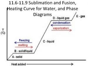
 Heating curve of water
 Heating curve of water
 Heating curve diagram
 Example of a sentence outline
 Wholesale panel solar cell
 Solar energy is free. solar is inexhaustible
 Payment systems outline
 Payment systems outline
 Payment systems outline
 Independent solar systems
 Alsa solar systems llc
 Ltt weert
 Solar radiation has a part in the water cycle by
 Climax solar water heater
 Solar dynamics barbados cost
 Solar panel heat exchanger
 Label heating curve
 Heating of the earth's surface causes
 Liz owns stock in nar
 Estimating air conditioning load software
 Heating of the earth's surface causes
 Comsol induction heating
 Thermal equilibrium
 Goddard heating and air
 Sea breeze
 Dielectric heating
 Tidal heating
 Define heating curve
 Heating mantle risk assessment
 This operates simply by heating air in an enclosed space.
 Adiabatic heating
 Limestone used in
 Sublimation fusion
 Lg therma v error code ch 14
 Frazier heating and cooling
 Measuring heat energy
 Advanced heating
 Principles of food preservation
 Central heating pump position
 Is charcoal heating a grill a physical or chemical change
 Cooling load calculation example
 B&l heating and air
 Spatula/scoopula
 Ise plumbing & heating
 Heating curve calculations
 Evergreen plumbing and heating
 District heating loan fund
 Bello heating and cooling
 Loose-fitting clothing
 Calcium carbonate carbon dioxide
 H&c heating and cooling
 Components of hvac system ppt
 Physical behavior of matter heating and cooling curves
 Used for holding hot objects especially crucible and cover
 Pure substance heating curve
 Southeast trade winds
 Termis district heating software
 Southampton geothermal heating company ltd
 Stage of cooking sugar
 Jon snow golden ratio
 Function of beaker tongs
 Heating and cooling curves
 Heating curve
 Thermo bello
 Schmitt heating and air
 Solid+heat
 Heating effect of electric current
 Superficial and deep heating modalities
 Sieb plumbing and heating
 Kale heating and cooling
 Ohmic heating
