Mechanical Design of Engine Parts P M V


 of cylinder wall is determined by thin")


 components produces bending action (also called")


- Slides: 60
Mechanical Design of Engine Parts P M V Subbarao Professor Mechanical Engineering Department Design for Survival …
MOST EXOTIC NEED OF HUMANS : Mobile Power : Animal Driven Vehicles 2
An Exclusive Thermodynamic Characteristic of Humans Life on Earth The humans are extra-somatic heterotrophs. Motive Power is An important Extra-somatic Need Autotrophs Heterotrophs
Human Evolution due to Mobility
Evolution of Intelligent Species : Artificial Horse World's first inexpensive car : In Benz Velo, 1893 0. 7 hp & 20 km/hr. 14 liters per 100 kilometers. World’s most fuel efficient car : Volkswagen's diesel-hybrid XL 1, 2013, 75 hp & 306 km/hr. 1. 0 liter per 100 kilometers
Busy Roads in 21 st century
A Faraday Future FF 91 electric car FF 91 is displayed on stage during an unveiling event at CES in Las Vegas, Nevada January 3, 2017. REUTERS/Steve Marcus
Prius : Toyoto Hybrid vehicle
The Type of Prime Mover for Light Vehicle Sales in Two Decades
Future Targets for Fuel Economy of LCVs
Major Components of A Multi Cylinder Engine Connecting rod
Characteristics of Real Engine at Maximum Fuel Consumption Control System of A Conventional I. C. Engine 12
The Ultimate Characteristic of Sustainable Creation
Engine Geometric Ratios Engine Compression Ratio Cylinder Bore-to-Stroke Ratio Kinematic Rod Ratio
Heat Loss Vs RBS
Frictional Loss Vs Geometry & Speed of Engine
Trending of Current Engines: Bore/Stroke Ratio Bore – to –Stroke Ratio
Extreme Limits of RBS • The extremes to this relationship is the inertial forces origination from the piston motion. • To achieve high power density, the engine must operate at a high engine speed (up to 18, 000 rpm for the Formula 1 engine), which leads to high inertial forces that must be limited by using a large bore-to-stroke ratio. • For applications that demand high efficiency, a small boreto-stroke ratio is necessary and, again because of the inertial forces of the piston, requires a slower engine speed and lower power density. • For the marine application that has a 2. 5 m stroke, the engine speed is limited to 102 rpm.
Kinematic Rod Ratio
Effect of Rod Ratio on ISFC : PI Engine
Effect of Rod Ratio on Heat Balance : PI Engine
Effect of Rod Ratio on Heat Balance
Indicative Specific Fuel Consumption
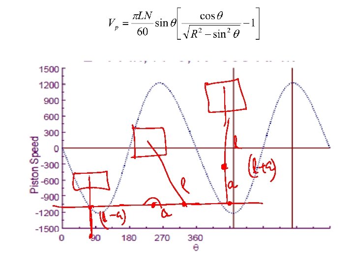
Piston Displacement & Speed Instantaneous Piston Displacement:
Piston Speed during High Load Conditions • For a four stroke engine: • For 1800 < q <3600 -Piston moves upward. • For 3600 < q <5400 - Piston moves downward. • The speed of the piston
Rod Ratio Vs Piston Speed • Short Rod is slower at BDC range and faster at TDC range. • Long Rod is faster at BDC range and slower at TDC range.
Role of Thermofluids on Engine Geometry • Thermodynamic performance decides the compression ratio. • Heat transfer and combustion mechanism decide the bore-to-stroke ratio. • Fuel economy and safety decide rod ratio. • These geometric ratios are to be taken as input to Mechanical Design of Engine parts. • What is next major information required for design?
The Ultimate Goal of Thermodynamic Modelling
Cold Period of Operation Hot Period of Operation
Combustion Generated Pressure-Crank Angle Diagram
In-cylinder Processes in a Diesel Engine
In-cylinder Processes in Next generation HCCI-DI Engine
Engine Cylinder – Piston system /injector
Cylinder & Cylinder Liner • Function: To retain the working fluid & guide the Piston.
Stress in Cylinder • Design of cylinder involves determination of wall thickness. • The forces: Force due to Gas Pressures & Side thrust. • Types of stresses generated: Longitudinal Stress, Circumferential Stress & Bending Stress due to side thrust. Net Longitudinal Stress Net Circumferential Stress
Design of Cylinder • The thickness (t) of cylinder wall is determined by thin cylinder formula. • Industry practice: The thickness (t) of cylinder wall is determined by an empirical formula.
Empirical Relations of Liner design • Liners are designed using empirical relations. Thickness of water jacket wall Thickness of water space : 10 mm for a bores below 75 mm. For bores greater than 75 mm.
The Piston
Design Considerations • In designing a piston for I. C. engine, the following points should be taken into consideration : • Strength to withstand the high gas pressure and inertia forces. • Minimum mass to minimise the inertia forces. • Form an effective gas and oil sealing of the cylinder. • Provide sufficient bearing area to prevent undue wear. • disperse the heat of combustion quickly to the cylinder walls. • High speed reciprocation without noise. • Rigid construction to withstand thermal and mechanical distortion. • support for the piston pin.
Design of Piston Head • The piston head or crown is designed keeping in view the following two main considerations, i. e. • Adequate strength to withstand the straining action due to pressure of explosion inside the engine cylinder. • Dissipate the heat of combustion to the cylinder walls as quickly as possible. • Simplification of Geometry & Loading • The top of the piston may be considered as a flat, fixed on the cylindrical portion of the piston crown. • subjected to uniformly distributed load of maximum intensity of gas pressure. • The thickness of the piston top (head) based on the straining action due to fluid pressure is given by
Geometry of Connecting Rod
Beam Cross-Section for connecting rod H-Beam I-Beam
Load Modeling Equations • Connecting rod load modeling considers • the static force applied by the piston which results from the combustion pressure, and • the dynamic load due to the linear oscillation of the piston mass. • Oscillating inertial force of the conrod is neglected in first approximation.
Loading equation: Compressive Force The compressive force aligned to conrod axis:
Loading equation: Tensile Force The tensile force aligned to conrod axis
Loading equation: Bending Force • Force due to inertia of the connecting rod or inertia bending forces. • Consider a connecting rod PC and a crank OC rotating with uniform angular velocity ω rad / s. • Draw the Klien’s acceleration diagram to find the acceleration of various points on the connecting rod. The inertia force acting on each point will be as follows: Inertia force at C = m × ω2 × CO Intertia force at D = m × ω2 × d. O Intertia force at E = m × ω2 × e. O, and so on.
Inertia Bending Forces • The perpendicular (or transverse) components produces bending action (also called whipping action) and the stress induced in the connecting rod is called whipping stress. • Resultant inertia force: Maximum bending moment
Design of Connecting rod • In designing a connecting rod, the following dimensions are required to be determined : • Dimensions of cross-section of the connecting rod, • Dimensions of the crankpin at the big end and the piston pin at the small end, • Size of bolts for securing the big end cap, and • Thickness of the big end cap.
cross-section of the connecting rod • The connecting rod is considered like both ends hinged for buckling about X-axis • and both ends fixed for buckling about Y-axis. • A connecting rod should be equally strong in buckling about both the axes. • Use Rankine’s formula
Bending Loads • Buckling Load about X-axis: • Buckling Load about Y-axis: A = Cross-sectional area of the connecting rod, l = Length of the connecting rod, σc = Compressive yield stress, Ixx and Iyy = Moment of inertia of the section about X-axis and Y-axis respectively, and kxx and kyy = Radius of gyration of the section about X-axis and Y-axis respectively.
Crank Shaft
Design Concepts for Crank Shaft • The crank shaft is designed considering two positions of the crank: • When Crank is at Dead centre (Maximum Bending Moment). • When Crank is at angle where Twisting Moment is maximum.
When Crank is at dead centre • Stepwise procedure: • Draw a Free Body Diagram of the Crankshaft with various horizontal and vertical forces. • Calculate the piston force. • Industry assumptions while calculation of forces in FBD. • Find all the horizontal & vertical reactions
When the crank is at an angle of maximum twisting moment • The twisting moment on the crankshaft will be maximum when the tangential force on the crank (FT) is maximum. • The maximum value of tangential force lies when the crank is at angle 30º to 40º for constant pressure combustion engines (i. e. diesel engines). • When the crank is at angle at which the twisting moment is maximum, the shaft is subjected to twisting moment from energy stored by flywheel. • The above design parameters can be cross checked for the factor of safety while designing by considering the crankshaft at an angle of maximum twisting moment.
Design Procedure for Crankshaft • The following procedure is adopted for designing a crankshaft. • Find the magnitude of the various loads on the crankshaft. • Determine the distances between the supports and their position with respect to the loads. • For the sake of safety, the shaft is considered to be supported at the centres of the bearings and all the forces and reactions to be acting at these points. • The distances between the supports depend on the length of the bearings, which in turn depend on the diameter of the shaft because of the allowable bearing pressures. • The thickness of the cheeks or webs is assumed to be from 0. 4 ds to 0. 6 ds, where ds is the diameter of the shaft. . • Now calculate the distances between the supports. • Assuming the allowable bending and shear stresses, determine the main dimensions of the crankshaft.
Design of Central Crankshaft
Hierarchical causes and modes of crankshaft failure
Crankshaft reliability improvement strategy