
SC 1 R Cold Box PDR Mechanical Design

SC 1 R Cold Box PDR Mechanical Design SC 1 R Cold Box Preliminary Mechanical Design Review S. Yang Tuesday, November 10, 2020
Outline § SC 1 R 2 K CBX Vessel - Overall Layout - Engineering Calculation - Cold compressor nozzle assembly procedure § Internal Piping Layout § Equipment Layout § Platform Conceptual Design § Entry Floor Grating Extension § Interface Piping § Summary SC 1 R PDR Mechanical Design 2
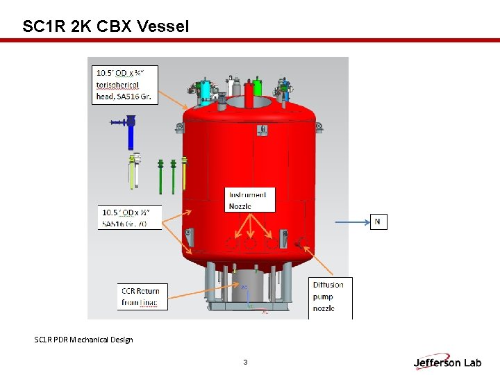
SC 1 R 2 K CBX Vessel SC 1 R PDR Mechanical Design 3
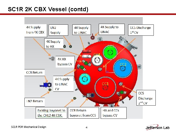
SC 1 R 2 K CBX Vessel (contd) CC 3 CC 4 CC 2 CC 5 CC 1 SC 1 R PDR Mechanical Design 4

SC 1 R 2 K CBX Vessel (contd) Minimum Thickness of the Shell Calculation Under External Pressure per UG-28 Vessel - SA 516 Gr. 70 Dv - OD, in Lv - design length, in tdr - required minimum thickness, in Lv / Dv Dv/ tdr Factor A Factor B Pa = 4*B*tdr/(3*D) Pa - calculated value of maximum allowable external pressure 126 138 0. 42 1. 10 300 2. 50 E-04 Subpart 3, Section II, Part D 3500 FIG. CS-2, Subpart 3, Section II, Part D 15. 6 YES Torispherical Head Thickness Cal per UG-33 Torispherical Heads Thickness Cal - UG-33 Pressure on Convex Side - SA 516 Gr. 70 UG-33 1 a method P - pressure 24. 5 psi E - joint efficiency 1 L - inside crown radius 126 in S - allowable stress 2. 00 E+04 psi t - the minimum thickness (=0. 885 PL/(SE-0. 1 P) 0. 0684 UG-33 1 e method t - minimum thickness A = 0. 125/(R/t) Factor B Pa = 4*B*tdr/(3*D) Pa - calculated value of maximum allowable external pressure SC 1 R PDR Mechanical Design 0. 230 4. 60 E-04 6. 20 E+03 15. 1 5 UG-33 1 a UG-32 e
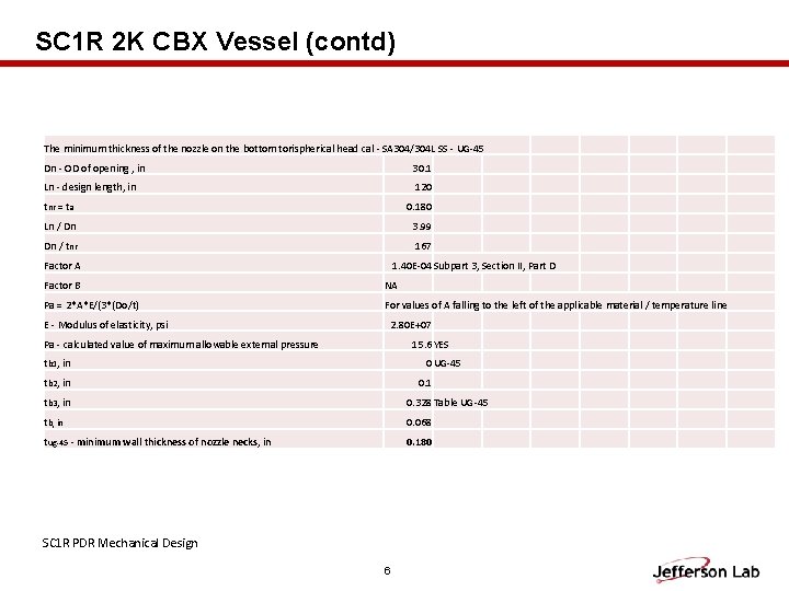
SC 1 R 2 K CBX Vessel (contd) The minimum thickness of the nozzle on the bottom torispherical head cal - SA 304/304 L SS - UG-45 Dn - OD of opening , in 30. 1 Ln - design length, in 120 tnr = ta 0. 180 Ln / Dn 3. 99 Dn / tnr 167 Factor A 1. 40 E-04 Subpart 3, Section II, Part D Factor B NA Pa = 2*A*E/(3*(Do/t) For values of A falling to the left of the applicable material / temperature line E - Modulus of elasticity, psi 2. 80 E+07 Pa - calculated value of maximum allowable external pressure 15. 6 YES tb 1, in 0 UG-45 tb 2, in 0. 1 tb 3, in 0. 328 Table UG-45 tb, in 0. 068 tug-45 - minimum wall thickness of nozzle necks, in 0. 180 SC 1 R PDR Mechanical Design 6
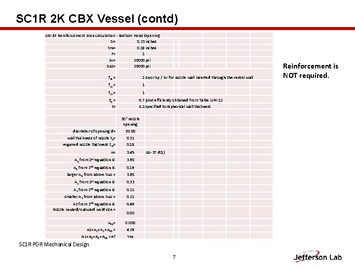
SC 1 R 2 K CBX Vessel (contd) UG-37 Reinforcement area calculation - Bottom Head Opening tr= 0. 23 inches trn= 0. 18 inches F= 1 Sv= 20000 psi Sn 1= 20000 psi fr 1 = 1 Sn or Sp / Sv for nozzle wall inserted through the vessel wall fr 2 = 1 fr 3 = 1 E 1 = t= diameter of opening d= 0. 7 joint efficienty obtained from Talbe UW-12 0. 5 specified torispherical wall thickness 30" nozzle opening 30. 00 wall thickness of nozzle tn= 0. 31 required nozzle thickness trn= 0. 18 A= 3. 45 A 1 from 1 st equation is: 3. 60 A 1 from 2 nd equation is: 0. 19 larger A 1 from above two = 3. 60 A 2 from 1 st equation is: 0. 33 A 2 from 2 nd equation is: 0. 21 smaller A 2 from above two = 0. 21 A 3 from 2 nd equation is: 0. 49 Nozzle inward/outward weld size = UG-37 d(1) 0. 00 A 41= 0. 000 A 1+A 2+A 3 +A 41 = 4. 29 A 1+A 2+A 3 +A 41 >A? Yes SC 1 R PDR Mechanical Design 7 Reinforcement is NOT required.
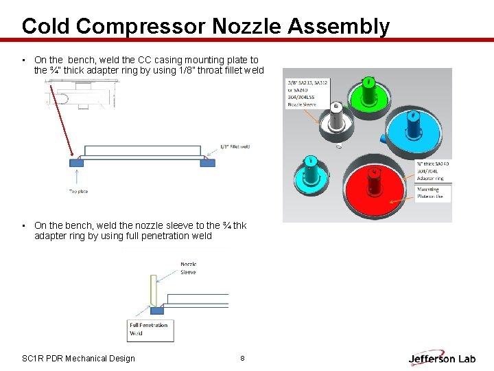
Cold Compressor Nozzle Assembly • On the bench, weld the CC casing mounting plate to the ¾” thick adapter ring by using 1/8” throat fillet weld • On the bench, weld the nozzle sleeve to the ¾ thk adapter ring by using full penetration weld SC 1 R PDR Mechanical Design 8

Cold Compressor Nozzle Assembly (contd) • Place the top head weldment on a stand be leveled. • Align the casing assembly to the top head. Tack weld first to make sure it is perfectly aligned then perform the full penetration weld to the thickness of the nozzle. • Will learn from the FRIB project about the generated moisture around the cold compressor. There are several options to handle the moisture depending on how much it will be. SC 1 R PDR Mechanical Design 9
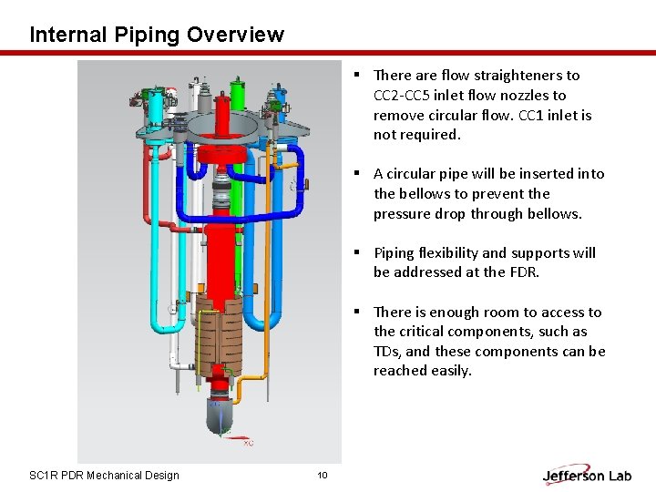
Internal Piping Overview § There are flow straighteners to CC 2 -CC 5 inlet flow nozzles to remove circular flow. CC 1 inlet is not required. § A circular pipe will be inserted into the bellows to prevent the pressure drop through bellows. § Piping flexibility and supports will be addressed at the FDR. § There is enough room to access to the critical components, such as TDs, and these components can be reached easily. SC 1 R PDR Mechanical Design 10
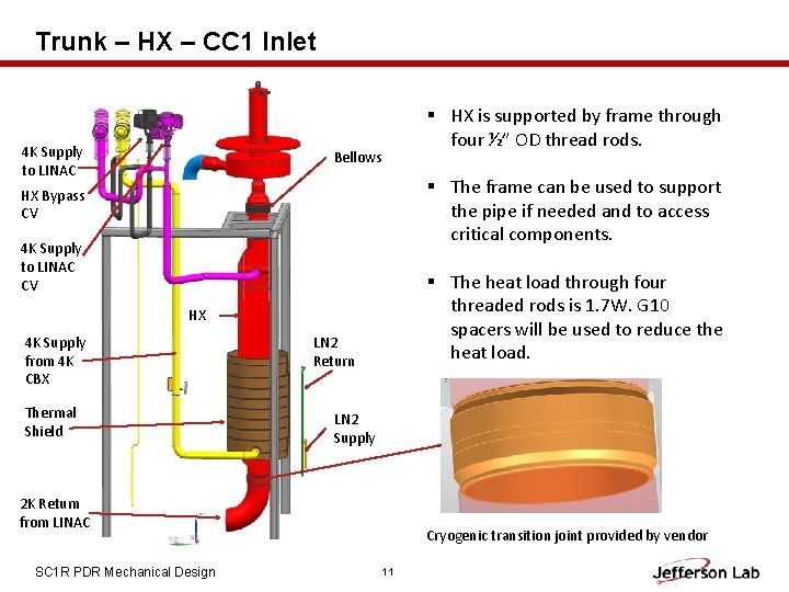
Trunk – HX – CC 1 Inlet 4 K Supply to LINAC Bellows § HX is supported by frame through four ½” OD thread rods. § The frame can be used to support the pipe if needed and to access critical components. HX Bypass CV 4 K Supply to LINAC CV § The heat load through four threaded rods is 1. 7 W. G 10 spacers will be used to reduce the heat load. HX 4 K Supply from 4 K CBX Thermal Shield LN 2 Return LN 2 Supply 2 K Return from LINAC SC 1 R PDR Mechanical Design Cryogenic transition joint provided by vendor 11
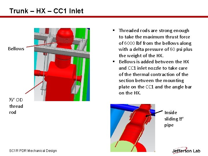
Trunk – HX – CC 1 Inlet Bellows § Threaded rods are strong enough to take the maximum thrust force of 6000 lbf from the bellows along with a delta pressure of 60 psi plus the weight of the HX. § Bellows is added between the HX and CC 1 inlet nozzle to take care of thermal contraction of the section between the mounting plate on the CC 1 and the angle bar on the HX. ½” OD thread rod SC 1 R PDR Mechanical Design Inside sliding 8” pipe 12
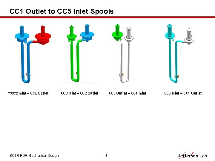
CC 1 Outlet to CC 5 Inlet Spools CC 2 Inlet – CC 1 Outlet CC 3 Inlet – CC 2 Outlet CC 3 Outlet – CC 4 Inlet CC 5 Inlet – CC 4 Outlet SC 1 R PDR Mechanical Design 13
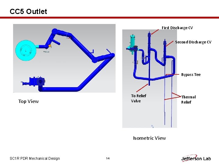
CC 5 Outlet First Discharge CV Second Discharge CV Bypass Tee To Relief Valve Top View Isometric View SC 1 R PDR Mechanical Design 14 Thermal Relief
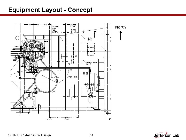
Equipment Layout - Concept North SC 1 R PDR Mechanical Design 15
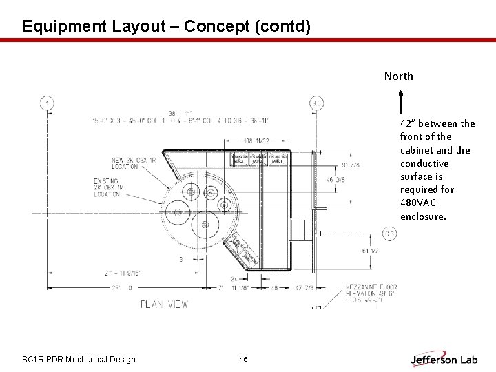
Equipment Layout – Concept (contd) North 42” between the front of the cabinet and the conductive surface is required for 480 VAC enclosure. SC 1 R PDR Mechanical Design 16
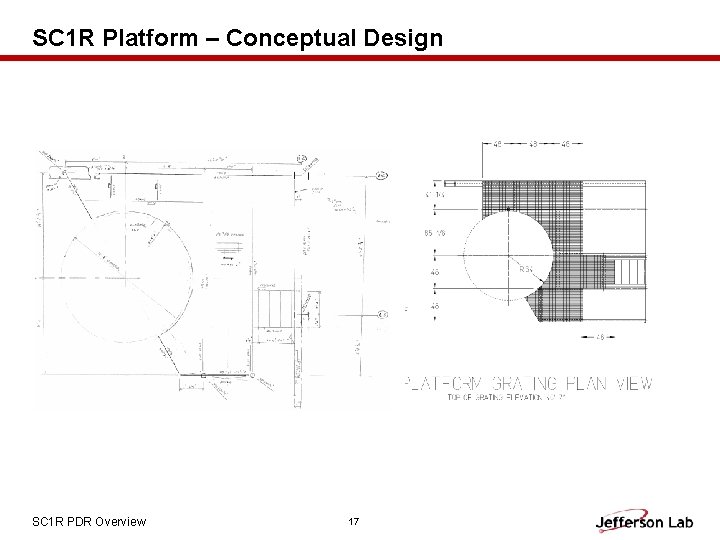
SC 1 R Platform – Conceptual Design SC 1 R PDR Overview 17

Entry Floor Grating Extension - Concept SC 1 R PDR Mechanical Design 18
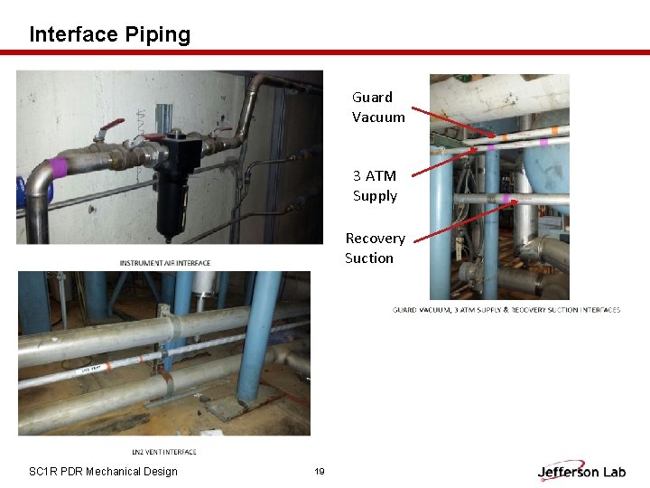
Interface Piping Guard Vacuum 3 ATM Supply Recovery Suction SC 1 R PDR Mechanical Design 19
Summary § The vacuum vessel is preliminarily designed per ASME VIII Div. 1 and 2. § The overall dimensions of the new vessel don’t require big modification of the building for installation. § FEA will be performed according to the Part 5 DESIGN BY ANALYSIS REQUIREMENTS, ASME VIII Div. 2 for normal operation mode using commercial software ANSYS 17. 2. § Internal piping is designed per ASME B 31. 3. § There is plenty room for access to the critical components. § Piping flexibility analysis will be performed using the commercial software Bentley Auto. PIPE for both the transportation and operation modes. § The cold compressors can be taken out of the vessel from the top head. § Interface piping has been identified and tie-ins have been marked. § The platform and grating conceptual design are well developed. SC 1 R PDR Mechanical Design 20

Thank You ! Tuesday, November 10, 2020
- Slides: 21