FCChh Detector FCC Overview of the Conceptual Design


- Slides: 33

FCC-hh Detector FCC Overview of the Conceptual Design Report W. Riegler for the FCC-hh detector study group March 4 th 2019

Same home for ee and hh Two High Luminosity IPs A/G Two Lower Luminosity IPs L/B Similar to layout at LHC We decided to work out one general purpose reference detector concept. Simulated performance of the subsystems was used for Physics Studies (DELPHES) Two main IP’s in A, G for both machines Patrick Janot Academic Training 11 Oct 2017

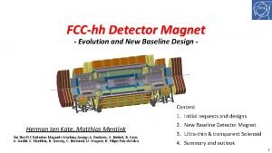
FCC-hh Reference Detector • • 4 T, 10 m solenoid, unshielded Forward solenoids, unshielded Silicon tracker Barrel ECAL LAr Barrel HCAL Fe/Sci Endcap HCAL/ECAL LAr Forward HCAL/ECAL LAr 50 m length, 20 m diameter similar to size of ATLAS

Comparison to ATLAS & CMS

Parameter Table … to define the specifications and requirement for such a detector. … to relate the challenges for detectors at the between LHC/HL-LHC/HE-LHC and FCC-hh.

Parameter Table 31 GHz of pp collisions Pile-up 1000 4 THz of tracks

Parameter Table First tracking layer: 10 GHz/cm 2 charged particles 1018 hadrons/cm 2 for 30 ab-1 Increased Boost at 100 Te. V ‘spreads out’ light SM physics by 1 -1. 5 units of rapidity.

Parameter Table 100 MHz of jets p T>50 Ge. V 400 k. Hz of Ws 120 k. Hz of Zs 11 k. Hz of Top

FCC-hh Reference Detector 50 m long, 20 m diameter Cavern length 66 m L* of FCC 40 m. 90% of ‘heavy‘ physics will take place in η<2. 5. Increase of acceptance for precision spectroscopy and calorimetry from 2. 5 at LHC to 3. 8 -4 for SM physics.

FCC-hh Reference Detector Cavern Distance of 50 m for • civil engineering • stray field reduction • Radiation shielding (1015 m would be sufficient) Service Cavern

Magnet System Central Solenoid + 2 Forward Solenoids Central Solenoid + 2 Forward Dipoles

Magnet System B B B compensation B B

Magnet System

Magnet System Parameters ATLAS Magnet System 2. 7 GJ CMS Magnet System 1. 6 GJ Cold Mass + Cryostat around 2000 tons.

Stray Field Less than 5 m. T in the Service Cavern, 200 -300 m. T outside the detector.

Material Distribution

Radiation Studies for L=3 x 1036 cm-2 s-1 and 30 ab-1 Maximum of 10 k. Hz/cm 2 of charged particle rate in the Barrel and Forward Muon System, similar to HL-LHC Muon Systems. In the tracker volume the charged particle rate is just a function of distance from the beampipe with rather small dependence on z. Hadron fluence in the order of 1018 /cm 2 close to the beampipe and 1015 -1016 /cm 2 (HL-LHC levels) for r>40 cm. Extreme fluences in the forward calorimeter … Triplet (z=40 m), Triplet shielding TAS (z=35 m) and related radiation are nicely ‘burried’ inside the tunnel.

Radiation Studies for L=3 x 1036 cm-2 s-1 and 30 ab-1 Dose of 300 MGy in the first tracker layers. <10 k. Gy in HCAL barrel and extended barrel. Dose from activation towards the end of FCC operation, 1 week of cooldown, so significant decrease for 1 month, 1 year.

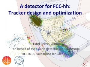
Tracker Layout Silicon tracker, two options studied, ‘tilted’ and ‘’flat’ layout’. 390 m 2 of silicon for tilted layout and 430 m 2 for flat layout. ATLAS CMS Phase-II silicon trackers have around 250 m 2. 25 -33. 3μm x 50 -400μm pixels for r < 200 mm 33μm x 400μm pixels for 200 mm < r < 900 mm 33μm x 2 -50 mm strips for 900 mm < r < 1600 mm This represents and r-phi resolution of 7. 5 -9. 5μm per detector layer 16 x 109 channels vs. 6 x 10⁹ and 2. 2 x 10⁹ for ATLAS/CMS Phase-II trackers

Tracker Material Budget A key advantage of the tilted layout is the reduced amount of material in the ‘transition’ region around η =2 -3. This results in a reduced probability for hadronic interactions and, together with the reduced propagation distance between layers, therefore in a higher reconstruction efficiency.

Tracker Momentum Resolution The momentum resolution is around 20% for p. T = 10 Te. V/c in the central region. The resolution limit due to multiple scattering is around 0. 5% in the central region. The material dominates the resolution up to p. T = 250 Ge. V/c. In the forward region beyond η = 3. 5 the momentum resolution deteriorates due to the ‘loss of lever arm’ in the solenoid field. Using dipole magnets in the forward region the momentum resolution can be kept below 1% even up to η = 6. The resolution curves for the solenoid field can be reproduced with the standard ‘pocket’ formulas.

Vertex Resolution d 0 and z 0 resolution of 30μm at η = 0 for p. T = 1 Ge. V/c, limited by multiple scattering.

Pileup, Timing, Tagging Average distance between vertices at z=0: 1 mm for HL-LHC (140 pileup) 125 um for FCC-hh (1000 pileup) As for HL-LHC, timing can help for vertex identification: B-tagging studies: Effective pileup: Number of vertices that a track of a given p. T is compatible with at 95% CL. B-Mesons with very high p. T travel far into the tracker and have a highly collimated decay tracks. For a time resolution of 25 ps, CMS can get to an effective pileup of 1 for 1 Ge. V/c tracks at η = 4. For an FCC detector the time resolution has to be at a level of 5 ps to get to similar numbers. The impact of pileup on a given physics analysis depends very much on the specific channels. Traditional taggers have difficulty in identifying the decay vertex. Using the ‘multiplicity jump’ between tracking layers due to a b decay can significantly improve the tagging performance.

Calorimetry LAr and Fe/Pb/Sci are used as reference technologies. Silicon calorimetry will be extensively ‘evaluated’ in the CMS Phase-II upgrade. The calorimeter system is ‘inspired’ by ATLAS (LAr, Tile. Cal), with increased granularity and with the forward for (η > 2. 5) moved to z=16. 5 m to make space for the forward tracker und to achieve coverage up to η = 6. For the EMCAL Barrel, the demand for increased granularity motivated a deviation from the ATLAS ‘accordion’ structure to a geometry with inclined plates. HCAL Barrel

EMCAL The Higgs mass resolution decreases from 1. 3% to 2. 3% when going from pile-up zero to pile-up 1000. These number do however not use any tracking information that can reduce the pileup effect.

HCAL Single pion resolution of the Barrel Calorimetry wo/o pileup Jet p. T resolution assuming zero magnetic field. With the 4 T B-field, about 15% of the charged particles within jets of momenta <100 Ge. V/c are not reaching the calorimeters. For jets with p. T > 1 Te. V/c the resolution is not degraded by the field. Studies on combined tracker/calorimeter performance have to be done next …

Muon Systems ‘Standalone’ muon performance is not any more a very important criterion. Future detectors rely on a combined tracker/muon system performance. The task of the muon system is triggering and muon identification. 4 -5% standalone momentum resolution can be achieved in at η=0, 30% at η=2. 5 by simply measuring the angle at which the muon exits the calorimeters. In the forward muon system, standalone momentum measurement and triggering can only be achieved when using a forward dipole (like ALICE, LHCb). The combined muon momentum resolution (tracker + muon system) can better than 10% even for momenta of 20 Te. V/c at η=0. Gas detectors similar to the ones employed for HL-LHC are good candidates for the muon systems.

Muon Systems Rate of muons for L=3 x 1035 cm-2 s-1 The muon rate is dominated by c and b decays. In contrast to leptonic decays from W, Z, t ( W l) these muons are not isolated but accompanied by particles that are seen in the calorimeters. ‘Isolation’ by using calorimeter information in addition the muon system is key for W/Z/t triggering.

Trigger/DAQ 100 MHz of jets p T>50 Ge. V 400 k. Hz of Ws 120 k. Hz of Zs 11 k. Hz of Tops

Trigger/DAQ Example: ATLAS Phase 2 calorimetry will be digitized at 40 MHz and sent via optical fibers to L 1 electronics outside the cavern at 25 TByte/s to create the L 1 Trigger at about 10 us latency. Muon system will also be read out at 40 MHz to produce a L 1 Trigger. Reading out the FCC detector calorimetry and muon system at 40 MHz will result in 200 -300 TByte/s, which seems feasible. 40 MHz readout of the tracker would produce about 1000 TByte/s. Question: Can the L 1 Calo+Muon Trigger have enough selectivity to allow readout of the tracker at a reasonable rate of e. g. 1 MHz ? Un-triggered readout of the detector at 40 MHz would result in 1000 -1500 TByte/s over optical links to the underground service cavern and/or a HLT computing farm on the surface.

Moore‘s Law http: //www. livescience. com/23074 -future-computers. html “If the doubling of computing power every two years continues to hold, then by 2030 whatever technology we're using will be sufficiently small that we can fit all the computing power that's in a human brain into a physical volume the size of a brain”, explained Peter Denning, distinguished professor of computer science at the Naval Postgraduate School and an expert on innovation in computing. "Futurists believe that's what you need for artificial intelligence. At that point, the computer starts thinking for itself. “ Computers will anyway by themselves figure out what to do with the data by 2035. 14/02/2014 W. Riegler, CERN

Heavy Ions The general purpose detector will also be able to perform well for Pb. Pb collisions at the predicted Luminosities. Continuous readout, PID from TOF with the timing detectors are good features for Heavy Ion Physics. Operating at a lower field than 4 T would of course be desirable (calibration questions to be worked out …) The significantly lower radiation requirement allows of course optimized detector solutions that can outperform a general purpose detector. We definitely have to keep the door open for a dedicated HI experiment setup.

Summary We have developed a general purpose reference detector concept for an FCC-hh collider. The detector and the performance for some benchmark channels is summarized in the FCC-hh CDR (30 pages). The concepts for the subsystems are simulated and parametrized to a level of detail that allowed serious physics studies to be performed. At this moment we are working on the detailed write-up of the work (150 pages). The development of ultra-radiation hard silicon sensors, low power radiation hard optical links, high granularity Liquid Argon calorimetry as well as high precision timing detectors are key detector R&D items. A next round of detector performance studies will have to look at combined performance of tracker & calorimetry as well as general pattern recognition issues in the pile-up = 1000 environment.
 Hfle;rf
 Fcchh
Fcchh Conceptual design vs physical design
 System design
 System design overview
 Hát kết hợp bộ gõ cơ thể
 Lp html
 Bổ thể
 Tỉ lệ cơ thể trẻ em
 Gấu đi như thế nào
 Chụp tư thế worms-breton
 Hát lên người ơi alleluia
 Môn thể thao bắt đầu bằng chữ đua
 Thế nào là hệ số cao nhất
 Các châu lục và đại dương trên thế giới
 Công thức tính thế năng
 Trời xanh đây là của chúng ta thể thơ
 Mật thư anh em như thể tay chân
 101012 bằng
 độ dài liên kết
 Các châu lục và đại dương trên thế giới
 Thơ thất ngôn tứ tuyệt đường luật
 Quá trình desamine hóa có thể tạo ra
 Một số thể thơ truyền thống
 Cái miệng nó xinh thế
 Vẽ hình chiếu vuông góc của vật thể sau
 Thế nào là sự mỏi cơ
 đặc điểm cơ thể của người tối cổ
 Thế nào là giọng cùng tên? *
 Vẽ hình chiếu đứng bằng cạnh của vật thể
 Fecboak
 Thẻ vin
 đại từ thay thế
 điện thế nghỉ
