Corrosion Introduction Corrosion Deterioration of a metal resulting


 placed in dilute HCL undergoes corrosion.")


, corroded")


: Cracking caused by combined effect of tensile")


 for W=183. 86, O=16, Na=22. 9, Hf =178. 5")


- Slides: 46
Corrosion
Introduction • Corrosion: Deterioration of a metal resulting from chemical attack by its environment. • Rate of corrosion depends upon temperature and concentration of reactants and products. • Metals have free electrons that setup electrochemical cells within their structure. • Metals have tendency to go back to low energy state by corroding. • Ceramics and polymers suffer corrosion by direct chemical attack. 13 -2
Oxidation – Reduction Reactions • A metal (Zn) placed in dilute HCL undergoes corrosion. Zn + 2 HCL Zn. Cl 2 + H 2 or Zn + 2 H+ Zn 2+ + H 2 also Zn Zn 2+ + 2 e- (oxidation half cell reaction) 2 H+ + 2 e. H 2 (Reduction half cell reaction) • Oxidation reaction: Metals form ions at local anode. • Reduction reaction: Metal is reduced in local charge at Local cathode. • Oxidation and reduction takes place at same rate. 13 -3
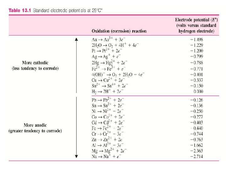
Standard electrode Half-Cell Potential of Metals • Every metal has a different tendency to corrode in a particular environment. • E. g. Zn is chemically attacked or corroded by dilute HCl acid whereas gold is not. • One method to compare the tendency for metals to form ions in aqueous solution is to compare their half-cell oxidation or reduction potential (voltage) to that of standard hydrogen-hydrogen ion half-cell potential. • The half-cell standard electrode potentials can be determined by experiment.
• Oxidation/Reduction half cell potentials are compared with standard hydrogen ion half-cell potential. • Voltage of metal (Zn) is directly measured against hydrogen half cell electrode.
Standard electrode Half-Cell Potential of Metals • When the switch is closed, the voltage between the half-cells is measured. • The potential due to the hydrogen half-cell reaction H 2 2 H+ + 2 e- is arbitrarily assigned zero voltage. • Thus, the voltage of the metal (Zn) half-cell reaction Zn Zn 2++ 2 e- is measured directly against the standard hydrogen half-cell electrode. (-0. 763 V)
• Those metal that are less reactive than hydrogen are assigned positive potential whereas those that are more reactive are assigned negative potential. • For those that are more reactive, the reactions involved are: M Mn++ ne- (oxidation) 2 H+ + 2 e. H 2 (reduction) • For those that are less reactive, the reactions involved are: H 2 2 H+ + 2 e- (oxidation) Mn++ ne. M (reduction)
Standard electrode Half-Cell Potential of Metals • Anodic to hydrogen More tendency to corrode Ø Examples: - Fe (-0. 44), Na (-2. 714) • Cathodic to hydrogen Less tendency to corrode Ø Examples: - Au (1. 498), Cu (0. 33) 13 -4
Macroscopic Galvanic Cells with 1 M Electrolyte • Two dissimilar metal electrodes immersed in solution of their own ions. • Electrode that has more negative oxidation potential will be oxidized. Oxidized Zn Zn 2+, Cu 2+ + 2 e- Reduced Cu Half cell reactions are Zn Zn 2+ + 2 e- E 0 = -0. 763 V Cu Cu 2+ + 2 e- E 0 = + 0. 337 V Or Cu 2+ + 2 e. Cu E 0 = -0. 337 V (negative sign) Adding two reactions, to get the electromotive force (emf): E 0 cell= -0. 763 V+(-0. 337 V)= -1. 1 V 13 -5
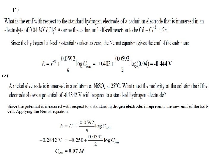
Galvanic Cells With Electrolytes less than 1 M • If the concentration of electrolyte surrounding anode is less than 1 molar, driving force for corrosion is greater. • There will be more negative emf half-cell anodic reaction M Mn+ + ne • Nernst Equation: E = Net emf of half-cell E 0 = Standard emf of half-cell N = Number of electrons transferred Cion = Molar concentration of ions. 13 -6
Galvanic Cells With Acid or Alkaline Electrolytes • Consider iron and copper electrodes in acidic electrolyte. • Since standard electrode potential of Fe to oxidize is – 0. 44 , compared to 0. 337 of copper, Fe Fe 2+ + 2 e • Since there are no copper ions to reduce 2 H+ + 2 e. H 2 • If electrolyte contains oxidizing acidic solution: O 2 + 4 H 4+ + 4 e 2 H 2 O • If electrolyte is neutral or basic (alkaline): O 2 + 2 H 2 O + 4 e 4 OH 13 -7
Microscopic Galvanic Cell Corrosion of Single Electrode • When single electrode is immersed in an electrolyte, microscopic cathodes and anodes are formed due to structural irregularities. • Oxidation reaction occurs at local anode and reduction reaction at local cathode. • If iron is immersed in oxygenated water, Fe Fe 2+ + 2 e- O 2 + 2 H 2 O + 4 e- 4 OH- 2 Fe + 2 H 2 O + O 2 2 Fe 2+ + 4 OH 2 Fe(OH)2 (precipitate) Fe(OH)2 is further oxidized 2 Fe(OH)2 + H 2 O + 1/2 O 2 2 Fe(OH)3 13 -8 Red-brown rust colour
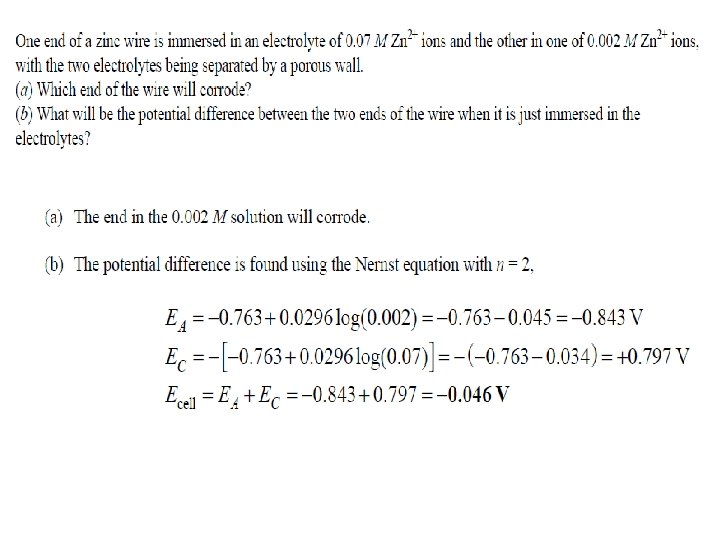
Concentration of Galvanic Cells • If a concentration cell is created by immersing 2 similar electrodes in electrolytes of different concentrations of same ion, electrode in dilute electrolyte will be anode. • Example: - 2 Fe electrodes immersed in electrolytes of 0. 001 M and 0. 01 M Fe 2+ electrolyte. E fe 2+ = E 0 + 0. 0296 log Cion for 0. 001 M E Fe 2+ = -0. 44 V + 0. 0296 log 0. 001 = -0. 529 V for 0. 01 M E Fe 2+ = -0. 44 V + 0. 0296 log 0. 01 = -0. 499 V • Since – 0. 529 V is more negative than – 0. 499 V, electrode in 0. 001 M solution is anode and gets corroded. 13 -9
Oxygen Concentration Cells • If two electrodes are immersed in electrolytes of different oxygen concentrations, electrode in low -oxygen content electrolyte is anode. • Example: Two iron electrodes, one in low oxygen concentration water and another in high oxygen concentration water. Anode reaction : Fe Fe 2+ + 2 e. Cathode reaction: O 2 + 2 H 2 O + 4 e 4 OH • Since cathode reaction requires O 2 and electrons, high concentration oxygen is cathode. 13 -10
Grain – Grain boundary Electrochemical cells • Grain boundaries are more anodic and hence get corroded by electrochemical attack. • Grain boundaries are at higher energy (due to atomic disarray). • Impurities migrate to grain boundaries. • Some alloy, solute segregation might cause grain boundaries to become more cathodic. Grain Boundary Grain boundary (anode) 13 -11 Cartridge Brass Grain boundary (cathode) anode Figure 12. 9
Multiple Phase Electrochemical Cells • In multiple alloys, one phase is more anodic than another. • Corrosion rates are higher in multiphase alloys. • Example: In pearlite gray cast iron, graphite flake is cathodic than surrounding pearlite matrix. Ø Anodic pearlite corrodes • Steel, in martensitic condition (single phase) after quenching from austenitic condition, has better corrosion resistance. • Impurities in metals leads to precipitation of Figure 12. 10 intermetallic phases and hence forms anodic and cathodic regions leading to corrosion. 13 -12
Rate of Uniform Corrosion • Faraday’s equation: W = weight of metal (g), corroded or electroplated in an aqueous solution in time t, seconds. I = Current flow A, i = current density A/cm 2 M = atomic mass of metal g/mol n = number of atoms/electron produced or consumed F = Faradays Constant =96, 500 A. s/mol A = area cm 2 • Corrosion rate is expressed as weight loss per unit area per unit time or loss in depth per unit time. • Uniform surface corrosion is often expressed as miligram weight loss per square decimeter per day (mdd). 13 -13
Given the atomic mass for tin is 118. 70 g/mol
Given the density for mild steel is 7. 87 g/cm 3
Passivation • Passivation is the loss of chemical reactivity in presence of a environmental condition. Ø Formation of surface layer of reaction products that inhibit further reaction. • Oxide film theory: Passive film is always a diffusion barrier of reaction products. • Adsorption theory: Passive metals are covered by chemisorbed films of oxygen. • Examples: - Stainless steel, nickel alloys, titanium and aluminum alloys. 13 -16
Types of Corrosion • Uniform or general attack corrosion: Reaction proceeds uniformly on the entire surface. Ø Greatest destruction of metal. ØControlled by protective coatings, cathodic protection. • Galvanic or two metal corrosion: Electrochemical reaction leads to corrosion of on metal. Ø Zinc coatings on steel protects steel as zinc is anodic to steel and corrodes. Ø Large cathode area to small anode area should be avoided. 13 -19
Pitting Corrosion • Pitting: Localized corrosive attacks that produces holes or pits in a metal. • Results in sudden unexpected failure as pits go undetected (covered by corrosion products). • Pitting requires an initiation period and grows in direction of gravity. • Pits initiate at structural and compositional heterogeneities. Figure 12. 20 Pitting of stainless steel 13 -20 Courtesy of La. Que Center for Corrosion Technology, Inc.
Growth of Pit • Growth of pit involves dissolution of metal in pit maintaining high acidity at the bottom. • Anodic reaction at the bottom and cathodic reaction at the metal Figure 12. 21 surface. • At bottom, metal chloride + water Metal hydroxide + free acid. • Some metals (stainless steel) have better resistance than others (titanium). 13 -21 After M. G. Fontana and N. D. Greene, “ Corrosion Engineering, ” 2 nd ed. , Mc. Graw-Hill, 1978
Crevice Corrosion • Localized electrochemical corrosion in crevices and under shielded surfaces where stagnant solutions can exist. • Occurs under valve gaskets, rivets and bolts in alloy systems like steel, titanium and copper alloys. • Anode: M M+ + e • Cathode: O 2 + 2 H 2 O + 4 e- 4 OH • As the solution is stagnant, oxygen is used up and not replaced. • Chloride ions migrate to crevice to balance positive charge and form metal Figure 12. 23 hydroxide and free acid that causes corrosion. 13 -22 After M. G. Fontana and N. D. Greene, “ Corrosion Engineering, ” 2 nd ed. , Mc. Graw-Hill, 1978.
Intergranular Corrosion • Localized corrosion at and/or adjacent to highly reactive grain boundaries resulting in disintegration. • When stainless steels are heated to or cooled through sensitizing temperature range (500 -8000 C) chromium carbide precipitate along grain boundaries. • When exposed to corrosive environment, the region next to grain boundaries become anodic and corrode. 13 -23
Stress Corrosion • Stress corrosion cracking (SCC): Cracking caused by combined effect of tensile stress and corrosive environment. • Stress might be residual and applied. • Only certain combination of alloy and environment causes SCC. • Crack initiates at pit or other discontinuity. • Crack propagates perpendicular to stress • Crack growth stops if either stress or corrosive environment is removed.
Erosion Corrosion and Cavitation Damage • Erosion corrosion: Acceleration in rate of corrosion due to relative motion between corrosive fluid and surface. • Pits, grooves, valleys appear on surface in direction of flow. • Corrosion is due to abrasive action and removal of protective film. • Cavitation damage: Caused by collapse of air bubbles or vapor filled cavities in a liquid near metal surface. • Rapidly collapsing air bubbles produce very high pressure (60, 000 PSI) and damage the surface. • Occurs at metal surface when high velocity flow and pressure are present. 13 -25
Erosion Corrosion
Fretting Corrosion and Selective Leaching • Fretting corrosion: Occurs at interface between materials under load subjected to vibration and slip. Ø Metal fragments get oxidized and act as abrasives between the surfaces. • Selective leaching: Selective removal of one element of alloy by corrosion. Ø Example: Dezincification Selective removal of zinc from copper and brasses. Ø Weakens the alloy as single metal might not have same strength as the alloy. 13 -26
Given the atomic mass for Al is 26. 98 g/mol, and the density for Al=2. 70 g/cm 3
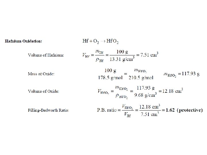
Oxidation- Protective Oxide Films • Oxides form on metals due to reaction with air. • Degree to which oxide films form depends on following factors. Ø Volume ratio of oxide to metal consumed after oxidation should be close to 1. Ø Good adherence. Ø High melting point of the film. Ø Low oxide pressure. Ø Coefficient of expansion equal to that of metal. Ø High temperature plasticity. Ø Low conductivity and diffusion coefficients of metal ions and oxygen. 13 -27
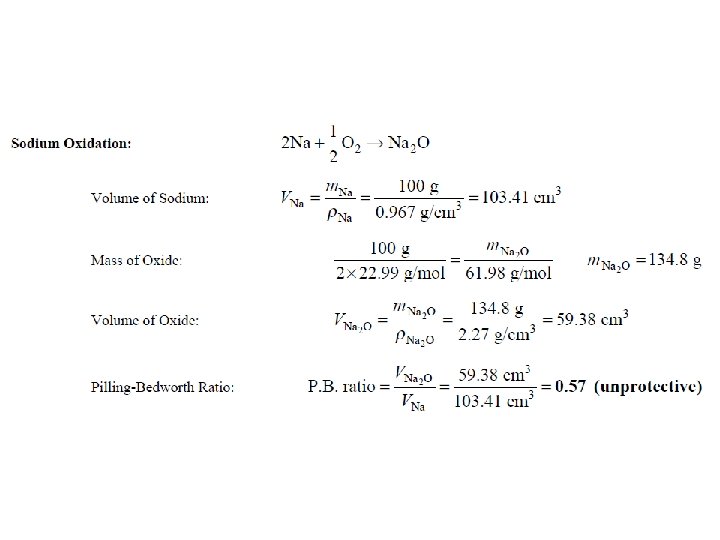
Oxidation- Protective Oxide Films The calculation of the volume ratio of oxide to metal after oxidation is a first step that can be taken to find out if an oxide of a metal might be protective. This ratio is called Pilling-Bedworth (P. B. ) ratio. If a metal has a P. B. ratio of less than 1, the metal oxide will be porous, and unprotective. If the ratio is more than 1, compressive stress will be present and the oxide will tend to Crack and spall off.
Given the atomic mass (g/mol) for W=183. 86, O=16, Na=22. 9, Hf =178. 5
Mechanisms of Oxidation • • • 13 -28 Oxidation partial reaction: M M 2+ + 2 e. Reduction partial reaction: ½ O 2 + 2 e. O 2 Oxidation starts by lateral expansion of discrete oxide nuclei. Metal diffuses as electrons or cations across oxide films. Sometimes O 2 - ions diffuse to oxide metal interface and electrons diffuse to oxide gas interface.
Corrosion Control
Material Selection Metallic Materials: • For reducing or nonoxidizing conditions such as air-free acid, nickel and copper alloys are often used. • For oxidizing condition, chromium –containing alloys are used. • For extremely oxidizing condition, titanium is often used.
Material Selection
Material Selection Nonmetallic Materials: • Polymeric materials such as plastic and rubber are less resistant to strong inorganic acids. • Ceramic have excellent corrosion and high temperature resistance. However they are brittle.
Coatings • Metallic Coatings • Inorganic Coatings • Organic Coatings
Design • Avoid excessive stress concentrations in corrosive environments to prevent stress -corrosion cracking. • Use weld rather than rivet containers to reduce crevice corrosion. • Design for easy draining and cleaning. • Avoid sharp bends in piping where flows occur. This is to prevent erosion corrosion caused by fluid direction change. • Deign systems for easy removal and replacement of parts that fail rapidly.
Alternation of Environment • • • Lowering temperature Decreasing the velocity of liquids Removing oxygen from liquids Reducing ion concentration Adding inhibitors to electrolytes