AC Circuit Analysis Sinusoidal SteadyState Analysis Contents CHAPTER

 Application of methods and theorem circuit to analyse the AC circuit")


 • Determine Io in the circuit using mesh analysis")

 • Find V 1 and V 2 in the")


")


- Slides: 54
AC Circuit Analysis Sinusoidal Steady-State Analysis
Contents (CHAPTER 10) Application of methods and theorem circuit to analyse the AC circuit eg • Nodal Analysis • Mesh Analysis • Superposition Theorem • Source Transformation • Thevenin and Norton Equivalent Circuits
Step to Analyze AC Circuits: 1. Transform the circuit to the phasor or frequency domain. 2. Solve the problem using method analysis or theorem circuit techniques. 3. Transform the resulting phasor to the time domain.
4 Independent Vs Dependent Sources • Independent sources: - The magnitude of the source is independent of the network to which it is applied & that the source displays its terminal characteristic even if completely isolated
5 Independent Vs Dependent Sources
6 Independent Vs Dependent Sources • Dependent/Controlled Sources: - One whose magnitude is determined (or controlled) by a current or voltage of the system in which it appears
7 Sources Conversion
8 Sources Conversion: Independent Sources
9 Sources Conversion: Independent Sources
10 Sources Conversion: Dependent Sources
11 Sources Conversion: Dependent Sources
Mesh Analysis Steps in determining mesh current for circuit contain with only independent voltage source: 1. Assign mesh currents i 1, i 2, …in to the n meshes Assign mesh current in the clockwise direction around each non redundant closed loop 2. Apply KVL to each of the n meshes. Use Ohm’s Law to express the voltages in terms of the mesh currents. 3. Solve the resulting n simultaneously equations to get the mesh currents by using substitution or determinants.
13 Mesh Analysis
14 Mesh Analysis The step if circuit contain with dependent voltage sources • Step 1 & 2 are the same as those applied for independent sources • Treat each dependent source like an independent source when Kirchhoff’s voltage law is applied to each independent loop. Once the eq. ready, substitute the eq. for the controlling quantity to ensure that the unknown are limited solely to the chosen mesh currents • Solve the resulting simultaneous linear equations
15 Mesh Analysis
16 Mesh Analysis The step if circuit contain with independent current sources • Step 1 & 2 are the same as those applied for independent sources • Treat each current source as an open circuit (recall the supermesh) & write the mesh eq. for each remaining independent path. Then relate the chosen mesh current to the dependent sources to ensure that the unknown of the final eq. are limited to the mesh currents • Solve the resulting simultaneous linear equations
17 Mesh Analysis
18 Mesh Analysis The step if circuit contain with dependent current sources • Step 1 & 2 are the same as those applied for independent sources • The procedure is essentially the same as that applied for independent current sources, except now the dependent sources have to be defined in term of the chosen mesh currents to ensure that the final eq. have only mesh current as the unknown quantities • Solve the resulting simultaneous linear equations
19 Mesh Analysis
20 Mesh Analysis
21 Mesh Analysis
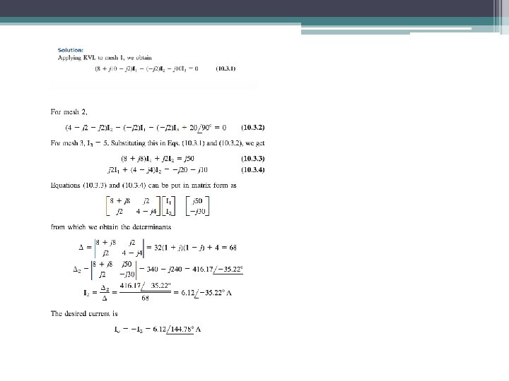
Example (10. 3) • Determine Io in the circuit using mesh analysis
Method Analysis • Nodal analysis 1. Steps to determine node voltage: i. Select reference node. ii. Assign voltage respect to reference node) iii. Apply KCL to each nonreference nodes. Use Ohm’s Law to express the branch currents. iv. Solve the resulting simultaneously equations to solve for node voltage to the remaining n-1 nodes (with
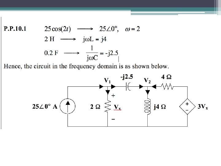
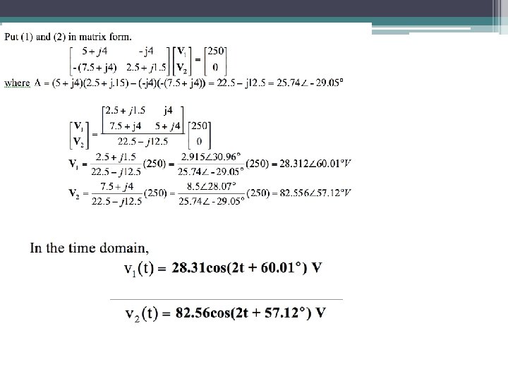
Example 1(P. P 10. 1) • Find V 1 and V 2 in the circuit using nodal analysis 25 cos (2 t) A
28 Nodal Analysis
29 Nodal Analysis
30 Network Theorems (AC)
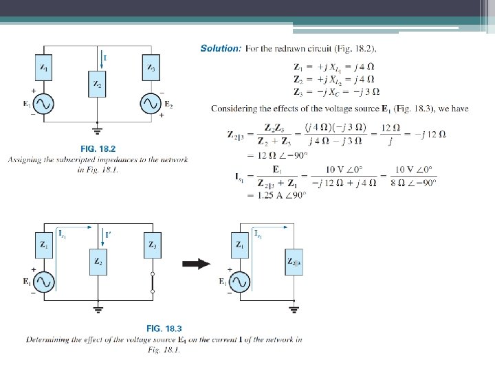
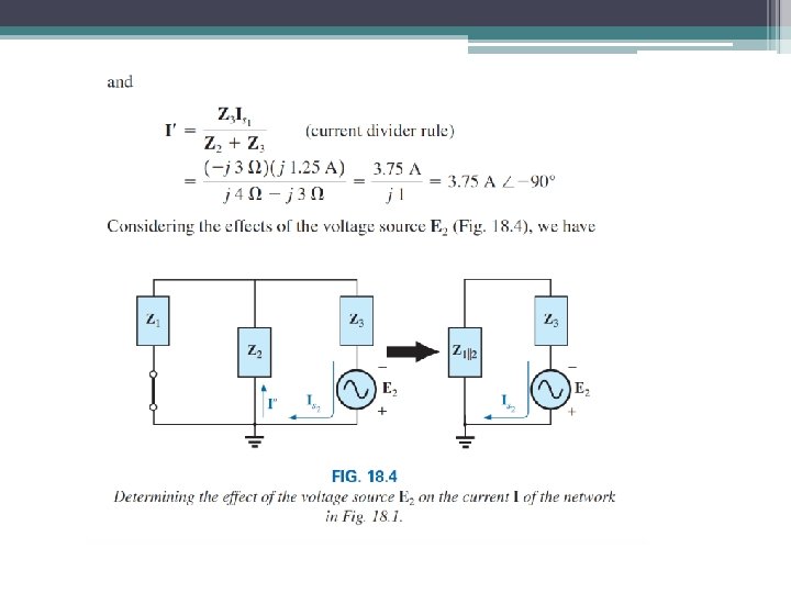
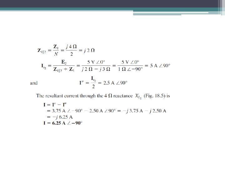
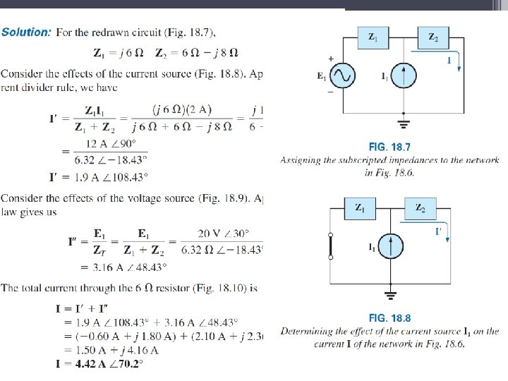
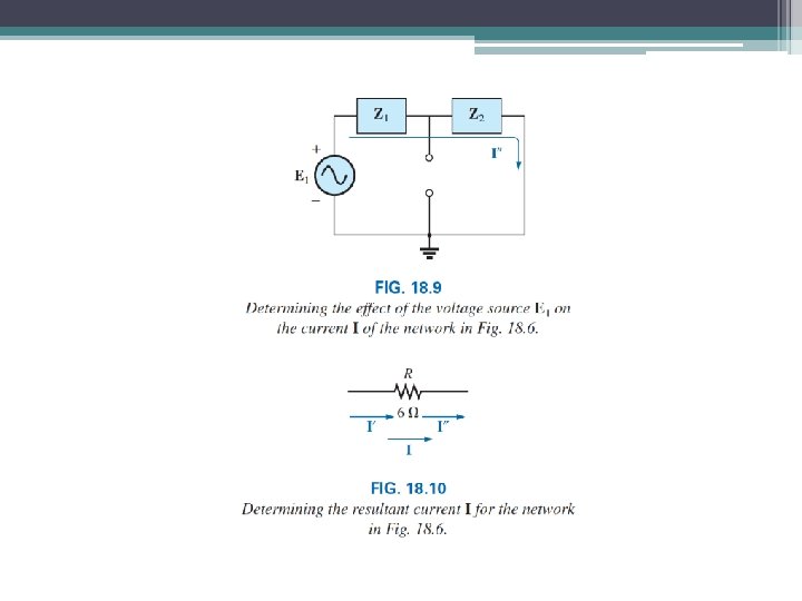
31 Superposition Find the current I using superposition theorem.
35 Superposition Find the current I using superposition theorem.
Thevenin and Norton Equivalent Circuit • Thevenin and Norton theorem applied to ac circuit in the same way as they are to dc circuit. Thevenin’s theorem states that a linear two – terminal circuit can be replaced by an equivalent circuit consisting of a voltage source VTH in series with a resistor ZTH, where VTH is the open circuit voltage at the terminals and RTH is the input or equivalent resistance at the terminals when the independent sources are turned off.
Norton’s theorem states that a linear two-terminal circuit can be replaced by an equivalent circuit consisting of a current source IN in parallel with a resistor ZN where IN is the short circuit current between two output terminals in the circuit and ZN is the total equivalent resistance at the terminals when the independent sources are turned off.
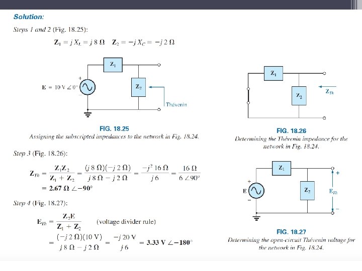
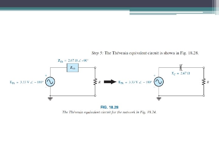
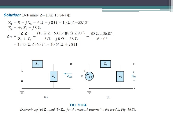
40 Thevenin’s Find the Thévenin equivalent circuit for the network external to resistor R
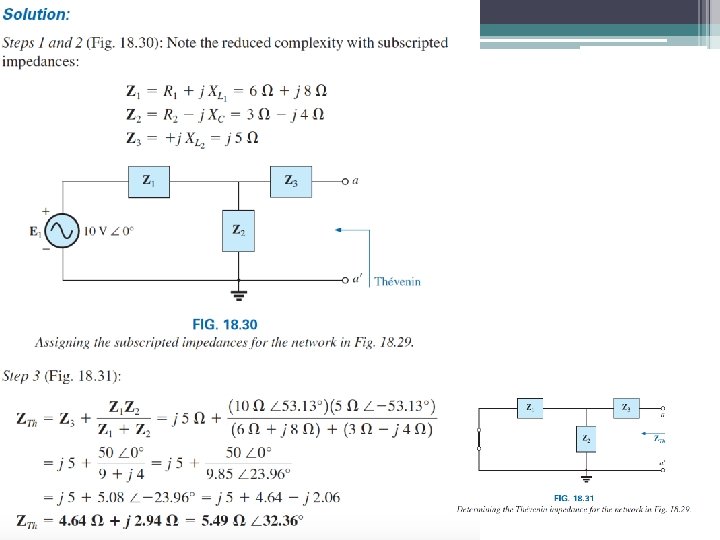
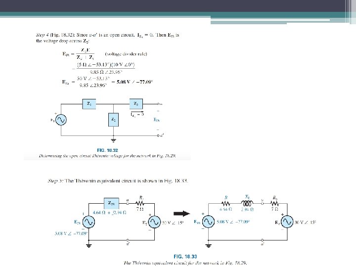
43 Thevenin’s Find the Thévenin equivalent circuit for the network external to branch a -a
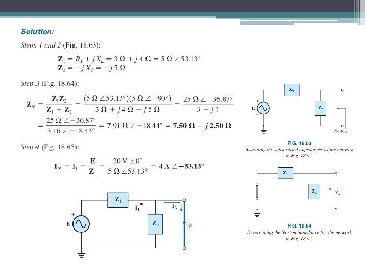
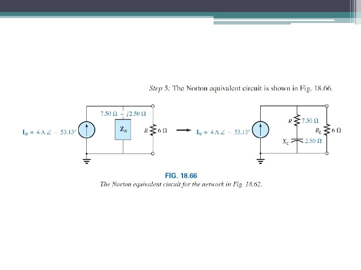
46 Norton’s Determine the Norton equivalent circuit for the network external to the 6 ohm resistor in this figure.
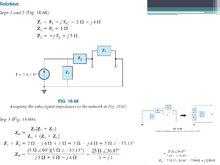
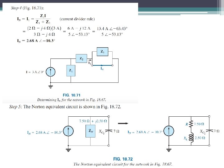
49 Norton’s Determine the Norton equivalent circuit for the network external to the 7 ohm capacitive reactance in this figure.
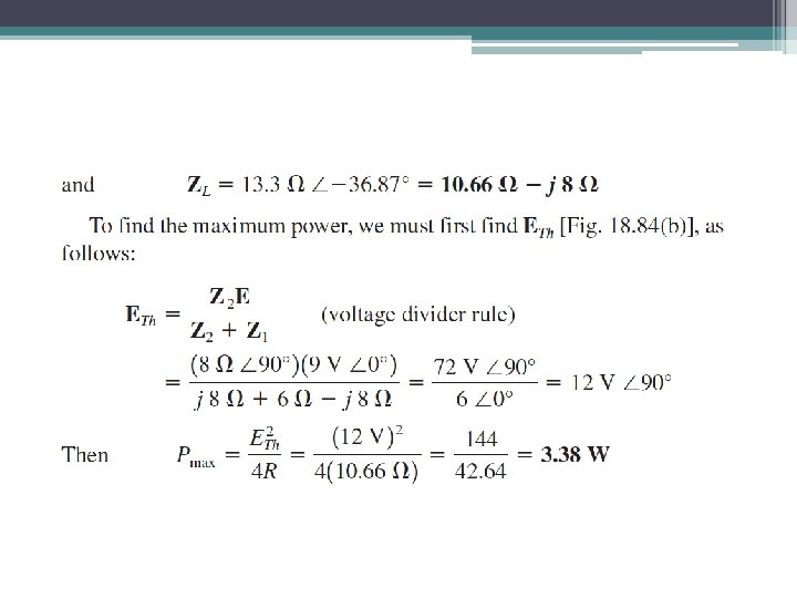
52 Maximum Power Transfer