Chapter 5 SteadyState Sinusoidal Analysis Chapter 5 SteadyState


- Slides: 74
Chapter 5 Steady-State Sinusoidal Analysis
Chapter 5 Steady-State Sinusoidal Analysis 1. Identify the frequency, angular frequency, peak value, rms value, and phase of a sinusoidal signal. 2. Solve steady-state ac circuits using phasors and complex impedances.
3. Compute power for steady-state ac circuits. 4. Find Thévenin and Norton equivalent circuits. 5. Determine load impedances for maximum power transfer. 6. Solve balanced three-phase circuits.
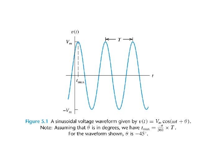
SINUSOIDAL CURRENTS AND VOLTAGES Vm is the peak value ω is the angular frequency in radians per second θ is the phase angle T is the period
Frequency Angular frequency
Root-Mean-Square Values
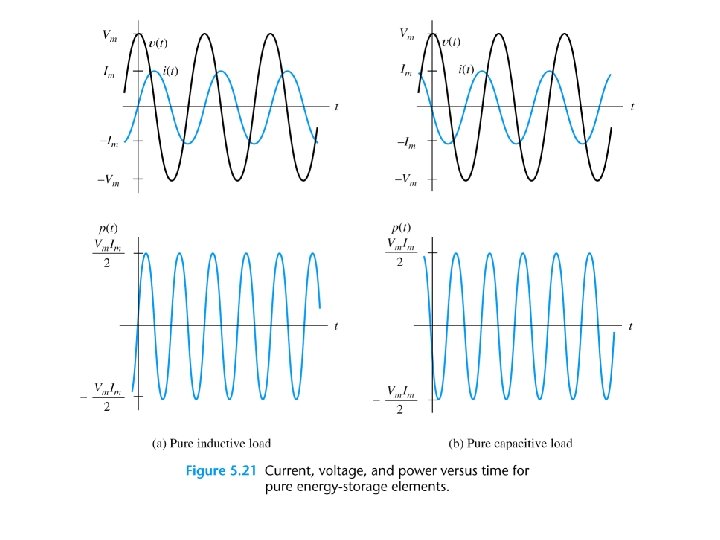
RMS Value of a Sinusoid The rms value for a sinusoid is the peak value divided by the square root of two. This is not true for other periodic waveforms such as square waves or triangular waves.
Phasor Definition
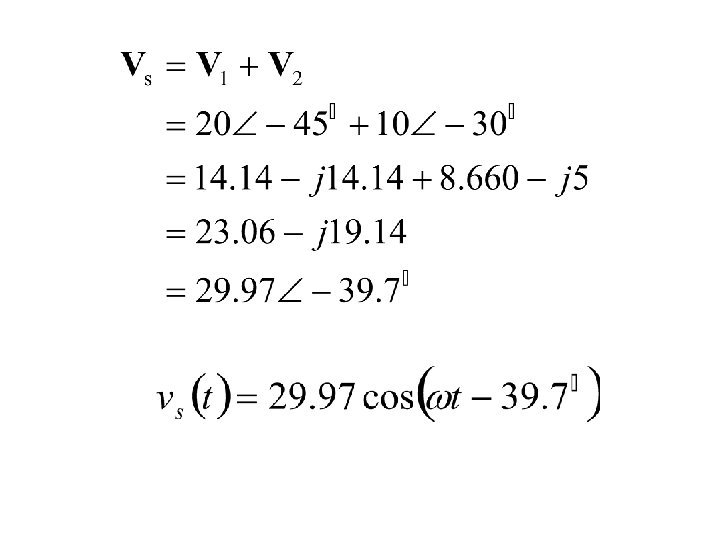
Adding Sinusoids Using Phasors Step 1: Determine the phasor for each term. Step 2: Add the phasors using complex arithmetic. Step 3: Convert the sum to polar form. Step 4: Write the result as a time function.
Using Phasors to Add Sinusoids
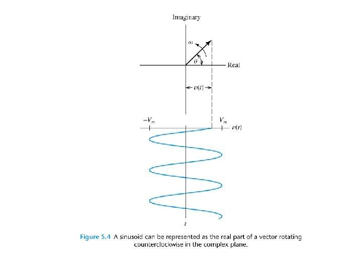
Sinusoids can be visualized as the realaxis projection of vectors rotating in the complex plane. The phasor for a sinusoid is a snapshot of the corresponding rotating vector at t = 0.
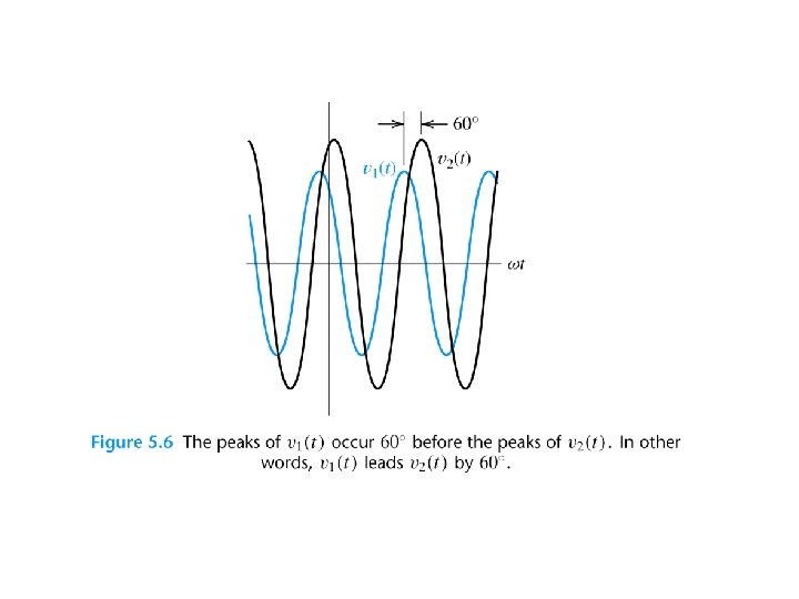
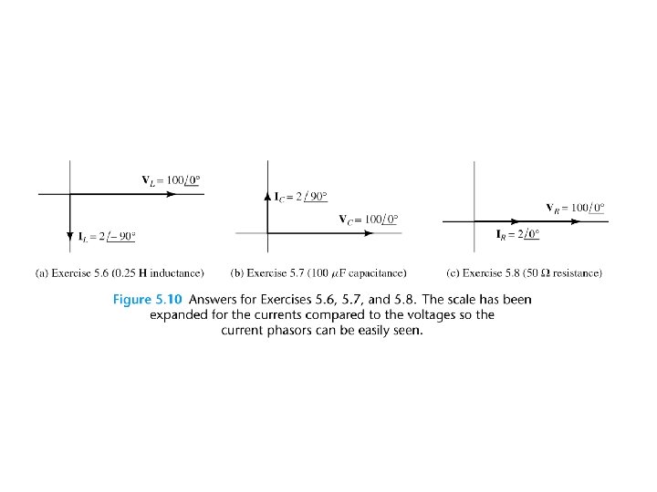
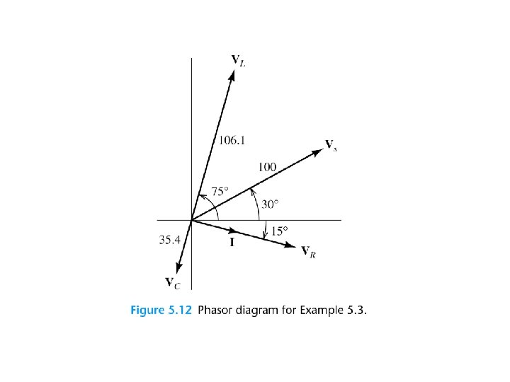
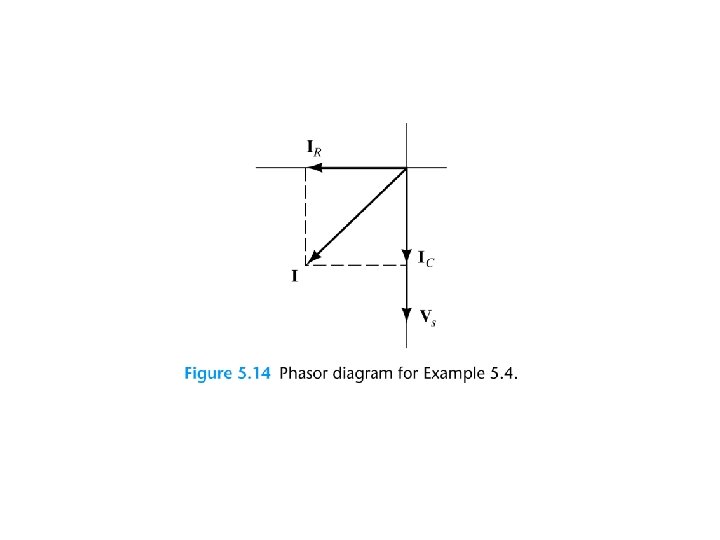
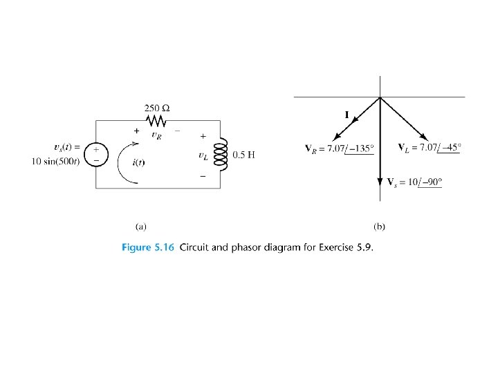
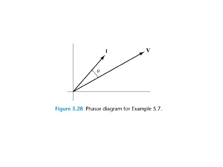
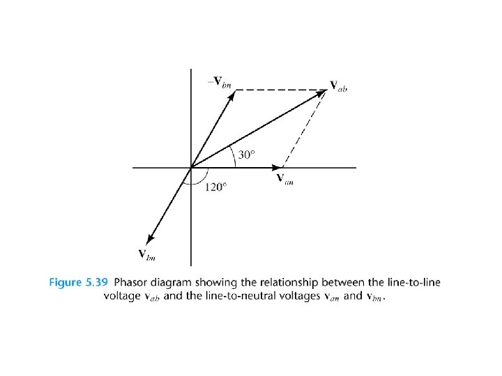
Phase Relationships To determine phase relationships from a phasor diagram, consider the phasors to rotate counterclockwise. Then when standing at a fixed point, if V 1 arrives first followed by V 2 after a rotation of θ , we say that V 1 leads V 2 by θ. Alternatively, we could say that V 2 lags V 1 by θ. (Usually, we take θ as the smaller angle between the two phasors. )
To determine phase relationships between sinusoids from their plots versus time, find the shortest time interval tp between positive peaks of the two waveforms. Then, the phase angle is θ = (tp/T ) × 360°. If the peak of v 1(t) occurs first, we say that v 1(t) leads v 2(t) or that v 2(t) lags v 1(t).
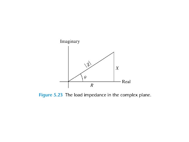
COMPLEX IMPEDANCES
Kirchhoff’s Laws in Phasor Form We can apply KVL directly to phasors. The sum of the phasor voltages equals zero for any closed path. The sum of the phasor currents entering a node must equal the sum of the phasor currents leaving.
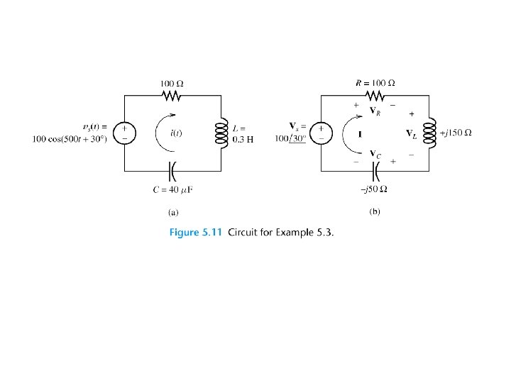
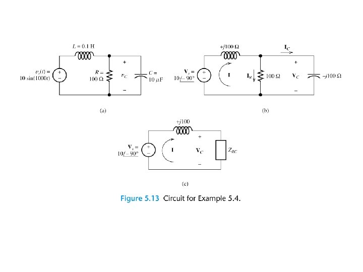
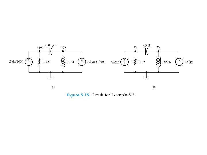
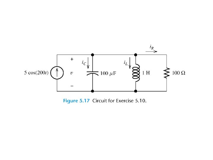
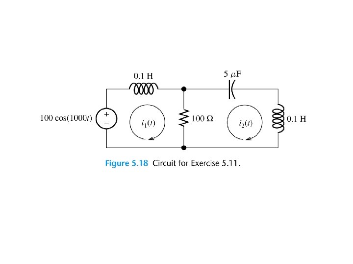
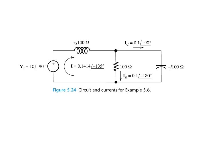
Circuit Analysis Using Phasors and Impedances 1. Replace the time descriptions of the voltage and current sources with the corresponding phasors. (All of the sources must have the same frequency. )
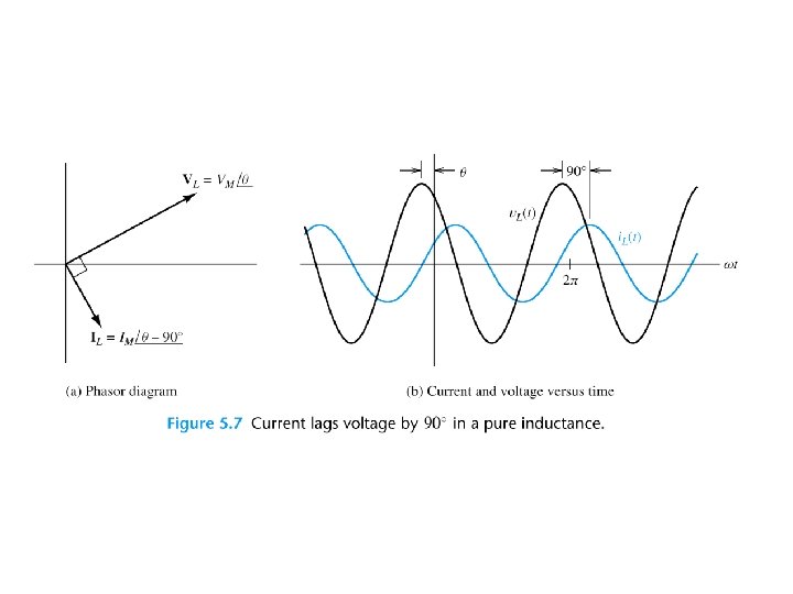
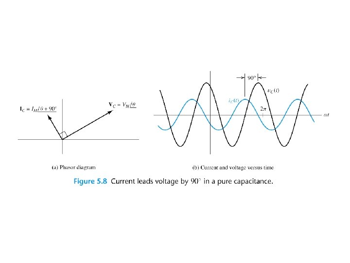
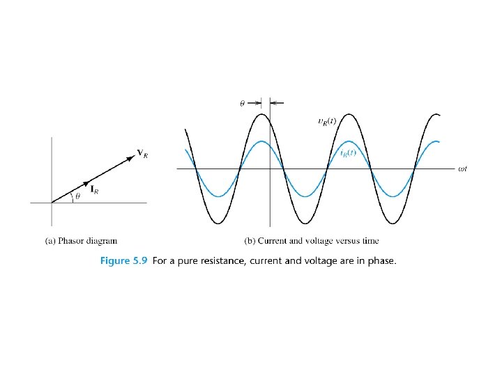
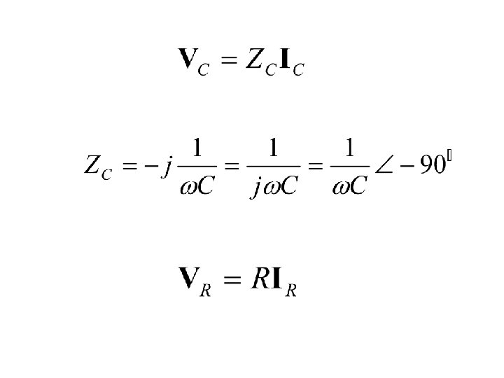
2. Replace inductances by their complex impedances ZL = jωL. Replace capacitances by their complex impedances ZC = 1/(jωC). Resistances have impedances equal to their resistances. 3. Analyze the circuit using any of the techniques studied earlier in Chapter 2, performing the calculations with complex arithmetic.
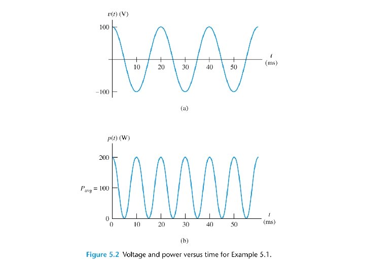
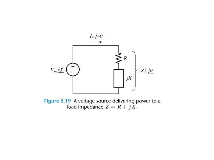
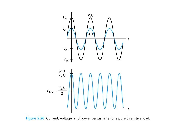
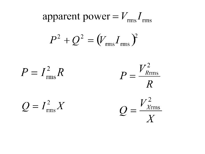
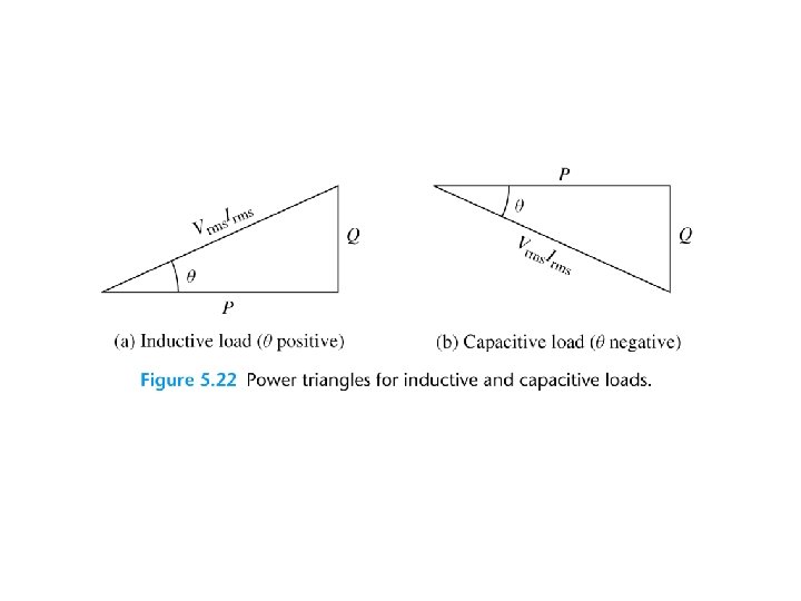
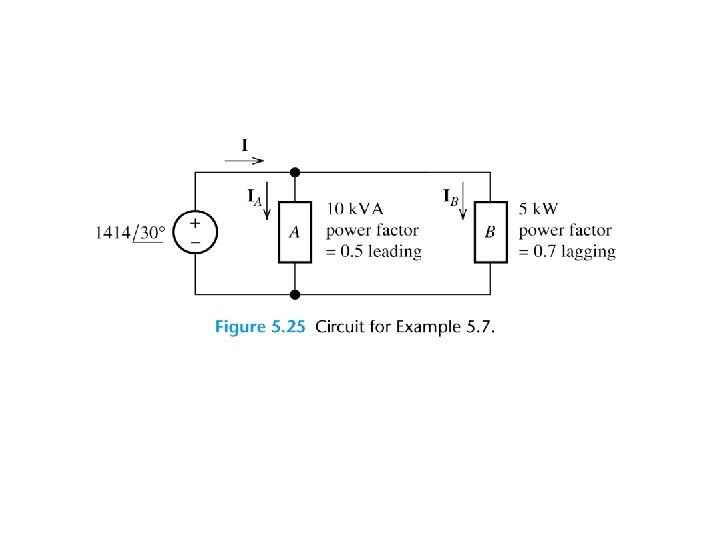
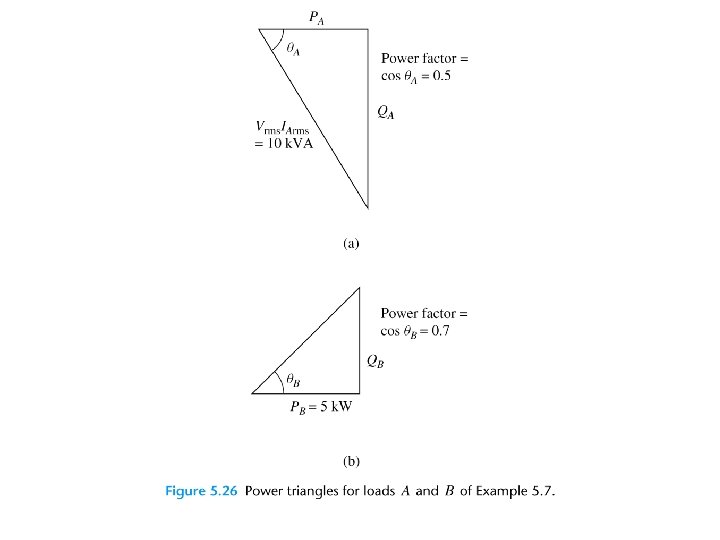
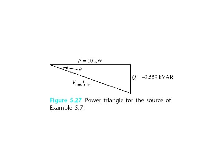
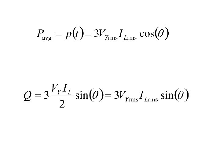
AC Power Calculations
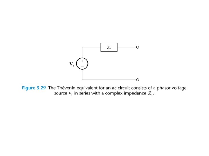
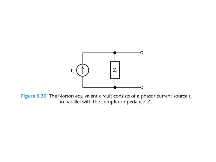
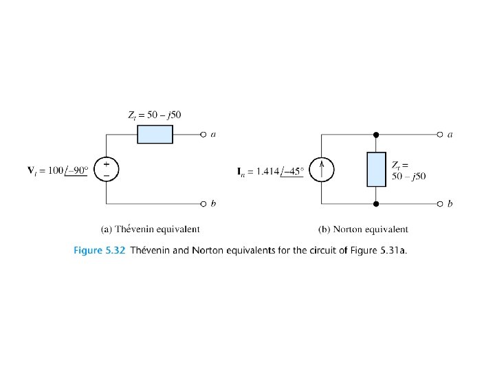
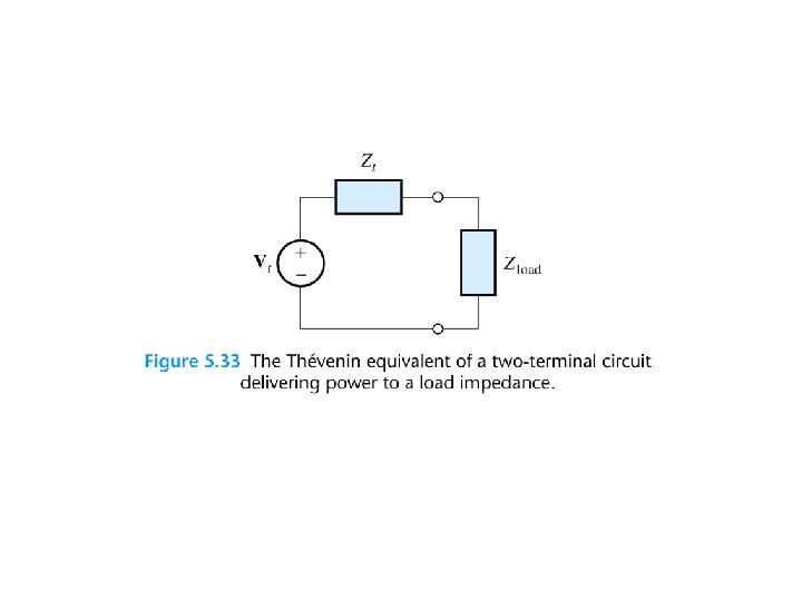
THÉVENIN EQUIVALENT CIRCUITS
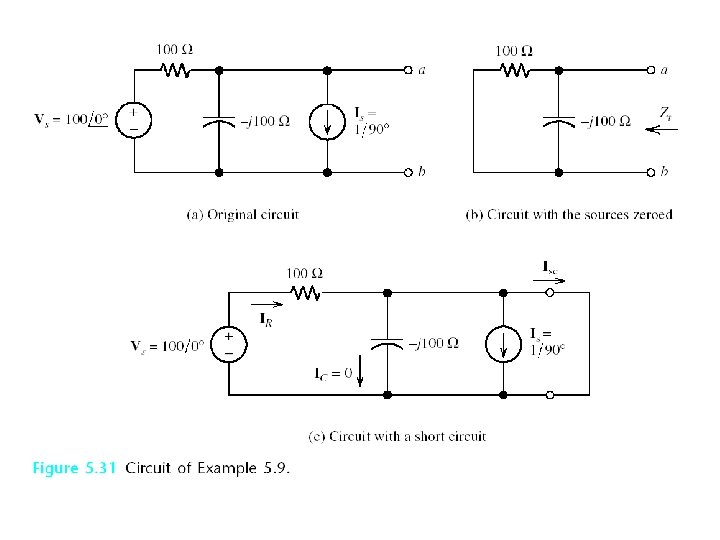
The Thévenin voltage is equal to the open-circuit phasor voltage of the original circuit. We can find the Thévenin impedance by zeroing the independent sources and determining the impedance looking into the circuit terminals.
The Thévenin impedance equals the open-circuit voltage divided by the short-circuit current.
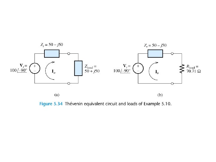
Maximum Average Power Transfer If the load can take on any complex value, maximum power transfer is attained for a load impedance equal to the complex conjugate of the Thévenin impedance. If the load is required to be a pure resistance, maximum power transfer is attained for a load resistance equal to the magnitude of the Thévenin impedance.
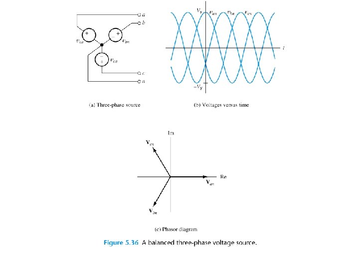
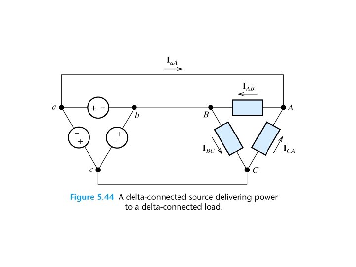
BALANCED THREE-PHASE CIRCUITS Much of the power used by business and industry is supplied by three-phase distribution systems. Plant engineers need to be familiar with three-phase power.
Phase Sequence Three-phase sources can have either a positive or negative phase sequence. The direction of rotation of certain three-phase motors can be reversed by changing the phase sequence.
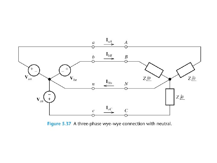
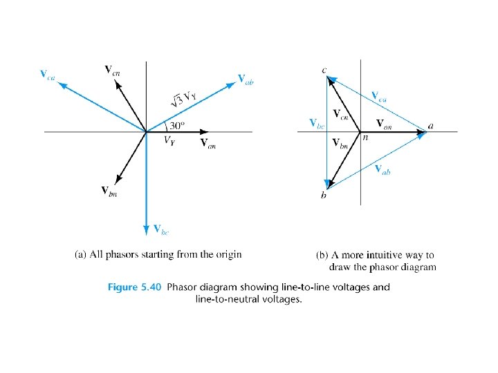
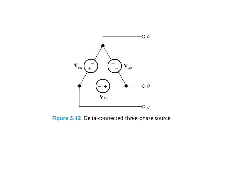
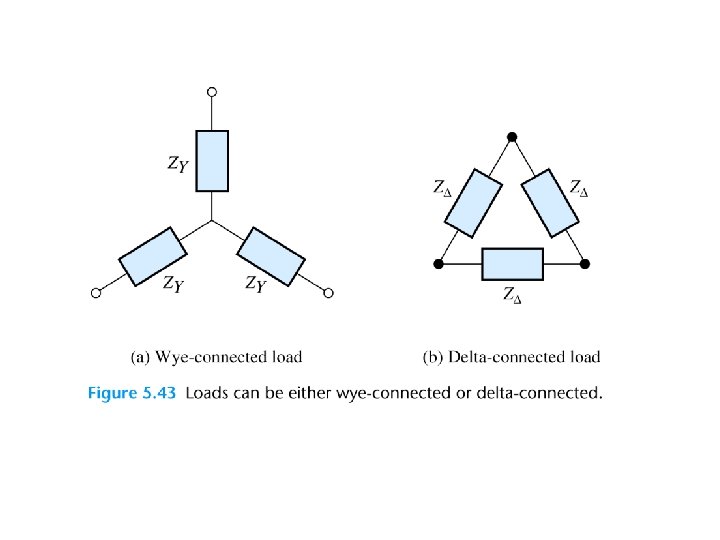
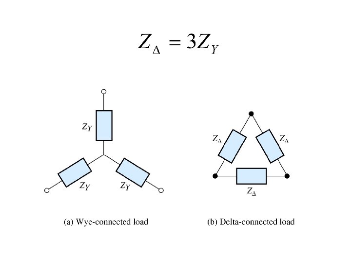
Wye–Wye Connection Three-phase sources and loads can be connected either in a wye configuration or in a delta configuration. The key to understanding the various threephase configurations is a careful examination of the wye–wye circuit.